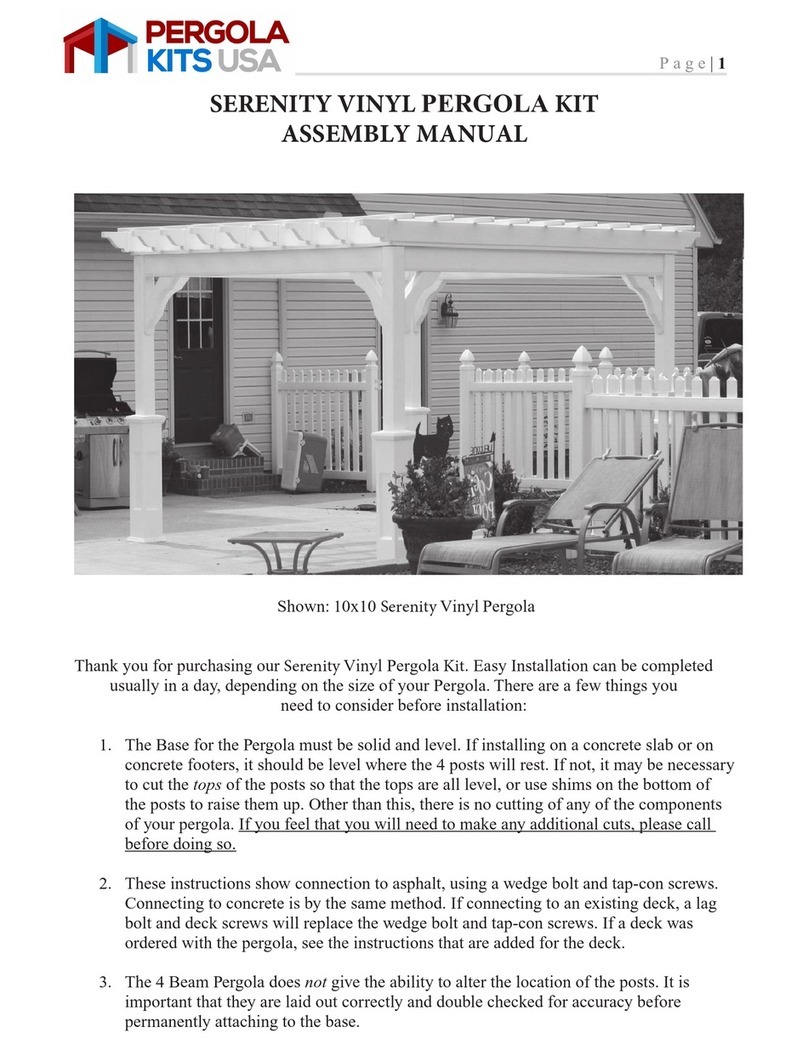
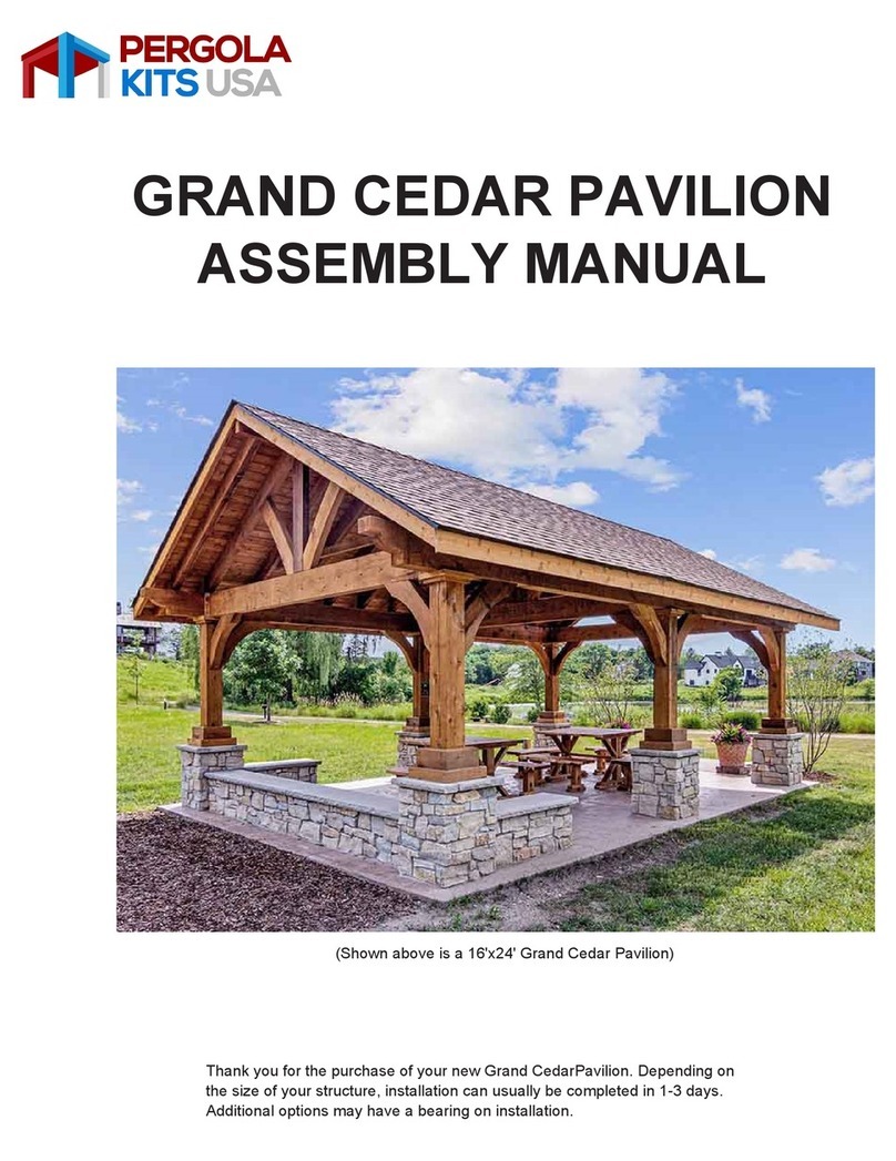
Pergola kits USA WOOD GABLE ROOF PAVILION User manual

WOOD GABLE ROOF
PAVILION ASSEMBLY
MANUAL
Shown above is an Open Gable Pavilion
Thank you for your purchase of a new Open Gable Pavilion. Depending on the size of your
Pavilion, installation can usually be completed in 1 to 2 days. These instructions are meant to
serve as a guide for people with a base knowledge of general handyman skills. This assembly
requires a minimum of two people to complete.

Before You Begin
Site Preparation
Tools Needed
2
Please always check with your local building codes, they will vary from state to state.
The base for the Pavilion must be solid and level. If installing on a concrete slab or on concrete footers, they
should be level where the posts will rest. If they are not, it may be necessary to cut the bottom of the posts
so that the bottoms are all level. Other than this, no cutting is necessary. If you feel that you will need to
make any additional cuts, please contact us before doing so. Making cuts without calling first may make
installation difficult or void our warranties.
When connecting to concrete, use wedge bolts, which are included in the kit. If connecting to an existing
deck, a lag bolt and deck screws (not included) will replace the wedge bolt.
The Pavilion does not give the ability to alter the location of the posts. It is important that they are laid out
correctly and double checked for accuracy before permanently attaching it to the base.
NOTE: These instructions are for building a standard, rectangular pavilion. “Eaves side” references the long
side and “gable side” references the short side (See front page image). If your pavilion has custom dimen-
sions with a longer gable side or square dimensions with equal sides, this reference point will need to be
adjusted appropriately by the builder during installation. CALL WITH ANY QUESTIONS.
It is important that the site is properly prepared before beginning assembly. It is imperative that the site
be level. There are a few choices when installing this structure, the two most common are to anchor the
posts to concrete pad/wood decking or attaching to a concrete footer or two Sonotubes. Sinking the
posts into the ground is not recommended unless it is called for by your local building codes.
Anchoring the posts to concrete/wood decking, is the most common method and is also the simplest.
Please provide a level concrete or wood decking surface, and then lay out the template on the surface.
Mark out the squares where the posts and brackets will go. Line up the markings that were made and
this is where to set the posts. Posts cannot be anchored into loose pavers or stone. Customer assumes risk
if not anchored into concrete or decking joists. This is the method that will be used for the following
instructions:
Please check with the local building codes for the depth required for the footers/concrete slab. Also if
using concrete footers make sure that all of the tops of the footers are level with each other before
starting to build. Contact your Project Advisor with any questions that you may have.
Hammer drill, hammer, level, tape measure, C clamps, socket set, ladder, circular saw

Notes:
An air-nailer or stapler can be used for rubber or asphalt shingles.
(Air nails and staples not included in the kit.)
There will be a parts list sent with the Pavilion. All hardware is included in each Pavilion kit.
The specific hardware will vary depending on the Pavilion. Please see the parts list for details.
3
1The Pavilion kit includes a
wooden template that will be
used to mark the post loca-
tions. Notice that two of the
2x4 boards have a marking
near the ends. Building a box
will reveal the outside corners
of the posts when properly
placed.
Connect the corners of the
template pieces by driving
two 2 1/2" screws through the
side of the template boards.
Arrange the template pieces
so that they are positioned in
the exact location of where
the Pavilion will be placed.
The boards with the marking
on the end will be across
from each other. The marks
will show where the other
boards will be attached to
create this box.
2
3

4
Once the template is in posi-
tion, square the template. Do
this by measuring diagonally
from one corner to its oppo-
site corner, then measure
diagonally between the other
two corners. These two
dimensions MUST be the
same. Adjust the template
until the diagonal measure-
ments are identical.
Begin by assembling the frame
of the Pavilion structure.
Please note that the Pavilion
kit includes some preassembled
pieces. NOTE: If you ordered
an electrical package, see
page 23 for installation
instructions before continu-
ing.
5
4
Once the template is “square”,
mark the post locations using
the
INSIDE
corners of the
framed box on the concrete
slab with a pencil. After all
the post locations are marked
on the concrete slab, remove
and set the wooden template
aside.
All of the posts will have two
sides notched. Turn the notches
on the post to the outside to
accept the headers.
4X
7
TOP
6

5
8
Assemble two posts and a beam
on the ground, starting with a
longer beam first. Make sure
your post is square with the
beam.
Repeat steps 7, 8, and 9 using
the other long beam and two
posts.
Attach the beam to the post
with two 3 1/2" screws. Do not
use the pre-drilled holes on
the beam. Those will be
used in step 18.
Slide your bottom post base
on the post. Be sure to slide
the bases up the post to make
room for completing steps
12-22.
NOTE: For HD High
Wind brackets see bracket
appendices on page 21
(Step 1) before moving on
to step 12.
11
TOP VIEW
9
10

Locate all 4 of your top rails. It
does not matter witch one you
put in first.
Once all four posts are posi-
tioned at the marks you
made using the template,
screw the 2x4 template to
the posts. Anchor one side
to the other in order to keep
it from falling over. (If you
have enough people to hold
the posts, you can forgo
attaching the template.)
Raise the connected posts and
beam. Be sure to align the posts
to the marks you made using the
template. You might need some-
one to hold it as you get the other
one.
Set one of your short beams
in place. Attach with three
3 1/2" screws through the
pre-drilled holes and into the
ends of the other beams.
Repeat this on the opposite
side with the last remaining
beam.
15
6
12
13
14

Make sure the posts are all
level and everything is square.
Fasten two L-brackets on the
outside edges of each post
with five 2 1/2" screws per
bracket.
NOTE: For HD
High Wind brackets see
bracket appendices on
page 21 (Step 2.)
Fasten rail to bottom of the
header with two 2 1/2" screws
approximately every 16". Do
that with all four sides.
Push rail up against the bottom of
the header. Put in center of post.
Fasten to post with four 2 1/2"
screws on both sides. Make sure
the screws on the braces are turned
in toward the inside of the building.
Locate 24 8" GRK screws in the
hardware box (if you have a
standard 4 post structure). Those
go in the pre-drilled holes at
the corners of the beams.
(6 per corner)
7
X2
19
6X
18
16
PUSH
17

2
Before inserting the bolt, make
sure dust is removed from
hole. Then screw the nut and
washer are on about 1/8”
below the top of the bolt. Next,
insert the wedge anchor bolt
into the hole. To protect the
threads and nut, tap the bolt
into the ground with a piece of
wood as a buffer.
When all posts have two L brack-
ets on, use a drill with 1/2" mason-
ry bit to drill down about 1/2"
farther than length of wedge
anchor.
Once the wedge anchor is
down against the bracket use a
wrench and tighten it. Do that
with all the anchors.
When all of the nuts have
been tightened down and
the posts are securely mount-
ed to the concrete slab, slide
the post trim down into place.
NOTE: If you ordered an
electrical package complete
step 6 of assembly instruc-
tions on page 24.
PUSH
8
22
23
1/2”
20
21

9
Position the 2x8 plate against the
2x12. (It is important that the
top plate boards equally over-
hang the structure to accu-
rately center the roof.) Fasten
the 2x8 to the 2x12 plate at the
corner with one 3 1/2" screw.
Once you have all four corners
together, put two 2 1/2" screws
down into the header approx-
imately every 16" all around.
Install the top plates. Position one
2x12 on the eaves side of the
pavilion. Center the plate so that
both ends fall at the same place
on the top of the post, visually
splitting the post-top from corner
to corner. Be sure the overhang
measurement matches on both
ends. Use two 3 1/2” screws to
fasten the plate.
DON’T CUT
WITHOUT CALLING.
25
27
Hold the first short-sided fascia
board in place with the mark
made resting on the outside
edge of the top plate. Also
both ends of the fascia board
should meet flush with the end
of the top plate boards. These
you might need to cut down
if needed.
Install the fascia boards. The
fascia will need to sit 1 1/8" (1
7/8" with metal roof) above
the top of the top plate boards.
Measure up 1 1/8" on the
board and make a mark. Do
this toward each inside end
of each fascia board, and
install the short sides first.
1 1/8”
26
24

Set the roofing sections in place
so the matching numbers
rest against each other. The
roofing sections will all be
marked in the top corner
with numbers.
When all fascia boards are
installed, set the four roof
panels on the outside of the
building. (You might need 3
or 4 helpers for this step.)
31
10
The eaves-side fascia boards will
overlap the gable-sides and will
extend out past them 11" (12" past the
top plate). Align the premarked line
with the end of the gable-side fascia
board ends. Attach the eaves-side
fascia to the top plate just as was done
with the gable-sides. The eaves-side
fascia will need to be connected to the
gable-side fascia boards with 2 1/2"
screws. Follow this process until all
fascia boards are installed.
Next, drive 2 1/2" screws every
16" along the entire length
of the fascia board. Follow
these same steps with the
other gable-side fascia board
as well.
28
29
30

Set the first roofing section
for the other side in place as
was done for the first section.
These two sections can now
rest against each other on
their ridge boards. Now, con-
nect these two ridge boards
together with one 2 1/2"
screw, staggered every 16"
apart. Make sure the ends of
panels are flush.
Once all the rafters are con-
nected, install the vertical
board of the gable sunburst
design. Make sure it is in the
center of the building. Fasten
with four 2 1/2" screws. Two
on top, two on bottom.
Lift the first section into place,
making sure the end is resting
on the top plate and against
the fascia board. The 12" over-
hang section should be against
the inside of the top plate and
flush with the outside of the
fascia board as shown. Use a
prop board to hold it in place.
(Prop board not included)
Do the same process with
the remaining sections until
all roofing sections are in
place. Once all sections are
in place, connect the inside
seams of all opposing sec-
tions. Do this by driving 2 1/2"
screws every 16" along the
seams.
11
BOTH
SIDES
33
35
34
32

2
12
37
39
38
There will be two different
size half-moon trim pieces.
The smaller one goes on top
of the fascia. The larger one
fits on the inside. Fasten the
half-moon trim pieces to all
three boards with one 1 1/2"
screws. Repeat the same pro-
cess on the inside.
Install the slant pieces. You
might have to cut them if they
do not fit. Fasten with two 2 1/2"
screws per board. (One on the
top and one on the bottom)
Now you are ready to install gable
end fascia. These are the boards
that have slant cuts on both ends.
It might need to be cut down to
size. Keep it flush on top of roof
panel and center of ridge beam.
Fasten to the 2x4 rafter. One
2 1/2" screw at top and two
at the bottom going into
fascia. Then one every 16".
36

Fasten the corner trim with
four 2 1/2" screws.
13
Once you have all the bottom
roof decking off, screw each
rafter down into plate with
one 2 1/2" screw down the
center and two 3 1/2" screws
angled on the sides.
Now you are ready to fasten
the rafter to the plate. First
take your bottom 1x6
roof
decking
board off. There
should be about two or three
screws you need to back out.
Make sure your ridge beam
does not sag in the center.
You might need to put a prop
in.
Once you have all the rafters
fastened, put your roof decking
board on again.
42
41
40
43

1
You are now ready to install the
shingles.
44
14
2
Installing Collar Ties
Your pavilion kit may include collar ties. Collar ties prevent the middle of the main beams from bowing
outwards due to the downward pressure of the roof due to gravity (i.e., the weight of the roof).
Identify the collar ties in your kit. A collar tie is a 2x4 (2x6 for larger sized
pavilions) with the ends mitred to match the pitch of your roof, like this:
If you have only one collar tie, you will fasten it to the center rafter (skip to
Step 4 on the next page). If you have more than one collar tie, space the
collar ties on the ground evenly along the length of the structure, each
collar tie directly below a rafter.
3Grab a collar tie and raise it up to the interior ceiling of the structure. Push
the collar tie up against the bottom of T&G so that the mitred end of the
collar tie is flush with the bottom of the T&G, and the 4” face of the 2x4 is
flush against side of your rafter.
For the purposes of these instructions, we will assume you have a 2x4 collar
tie, rather than a 2x6.

Install the drip edge over the
bottom lath piece. Cut each
piece to length. Fasten with
1" screws, staples, or nails
every 16".
2
Roofing Option 1:
Installing A Metal Roof
Fasten horizontal "Roof Lath"
pieces with two 2" roofing
nails at each rafter. Place the
first piece of lath directly on
top of the lowest decking
board. Space each lath board
roughly 20-24" apart with the
longest piece placed at the
bottom and the shortest piece
at the top. (Lath boards may
need to be cut to length.)
LATH
LATH
LATH
LATH
1
Fasten the collar tie to the
rafter with six 2 1/2" screws at
each end of the collar tie.
4
Collar Tie
Typically 2x4 or 2x6
15

16
Install the tin, starting at right
side and moving left. Ensure
the first piece is installed
squarely. Keep the bottom of
the tin flush with the drip
edge. Fasten with 1” screws.
The first piece will have 3
screws at every lath.
Once you have all the tin
installed, hold the gable end
trim in place to mark the upper
end of the trim that will need
to be cut to meet flush with
the other side.
Install the ribbing roughly
1 1/2-2" from the bottom of
the drip edge. Do not stretch
the ribbing because the
grooves of the roof must
line up with the ribs.
The next piece must properly
overlap on the far edge. Last
piece may need to be cut to
size to be flush with the edge
of the fascia.
6
3
5
CUT TRIM AT PEAK
4

8
9
When complete, repeat steps
6-8 on the other gable end.
Once gable end trim is cut to
angle, attach the trim piece
with one 1” screw into the
fascia board every 24” of the
open gable end. Next, fasten
the top of the same trim piece
with 1” screws at every roof
lath.
Locate ridge cap. Remove
backing from foam and
attach to the underside of
the ridge cap. Place ridge
cap, flush with previously
installed trim, fastening every
24” with 1 1/2” screws on both
sides.
7
17

18
Roofing Option 2:
Installing An Asphalt Roof
NOTE: Before you begin the steps below, install roof paper starting at the bottom. Be sure to overlap 2" as
you work upward. Drip edge will then be installed on all edges of the roof, using a fastener every 16".
Roofing Fasteners
Please note we do not include fasteners for asphalt shingles with our kits. This is because some states
require different fasteners than others, and because some customers have different tools than others
(hammer, nail gun, pneumatic stapler, hammer tacker, etc.).
Please use shallow depth fasteners to fasten your shingles to your 1x6 roof decking. For example:
• 5/8” long roofing nails
• Roofing staples with 5/8” leg and 1” wide crown
These fasteners will certainly be sufficient to hold the shingles to your roof in high storm winds, and will
not pierce the bottom surface of the 1x6 roof decking.
DO NOT PLACE PLYWOOD, OSB (ORIENTED STRAND BOARD) OR OTHER
DECKING ON TOP OF THE 1X6 TONGUE AND GROOVE.
It is not necessary and is too heavy for your structure.
1
To install 1st row of shingles,
turn shingle upside down
with black tar line at bottom
edge facing up and attach to
roof using four 5/8” roofing
nails. Place nails approximately
3” from bottom.

Attach second row of shingles
to the roof using 5/8” roof
nails provided or a power
stapler. Do not use long nails
or staples that protrude
through 1X6 roof decking.
4
19
5
Use four 5/8” roofing nails
and attach to roof through
shingle at the center line
marked on the shingle. Do
not fasten below the line or
your fasteners will be exposed.
2
3
Start second row, line up
bottom of shingle with the
architectural line on the
shingle below.
CUT SHINGLES
AT ROOF’S EDGE
Trim corner shingles using a
shingle scissor or utility knife.
When using a knife cut on the
bottom side.

20
6
Also see instructions on
shingle package.
9
Work across then up. Continue
to the top.
7
Start at both ends of ridge
and work toward the center
of the ridge.
8
Last piece will need cut in half
and will bring the corners
together.
Other manuals for WOOD GABLE ROOF PAVILION
1
Table of contents
Other Pergola kits USA Outdoor Furnishing manuals

Pergola kits USA
Pergola kits USA WOOD SERENITY PERGOLA User manual

Pergola kits USA
Pergola kits USA GRAND CEDAR PAVILION User manual

Pergola kits USA
Pergola kits USA LANDMARK PAVILLION User manual

Pergola kits USA
Pergola kits USA NEWPORT PERGOLA KIT User manual

Pergola kits USA
Pergola kits USA Serenity Vinyl Pergola Kit User manual

Pergola kits USA
Pergola kits USA Single-Beam Free-Standing Pergola User manual