Page | 5
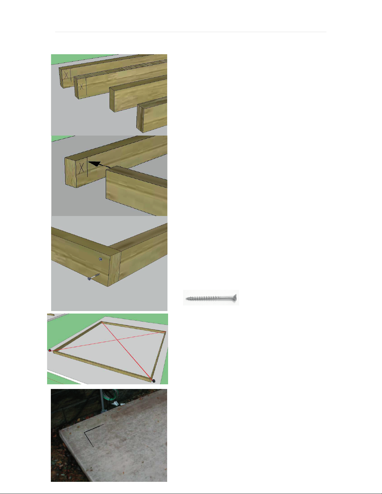
top plates as some of the sides will need more than one board.) Two of the top
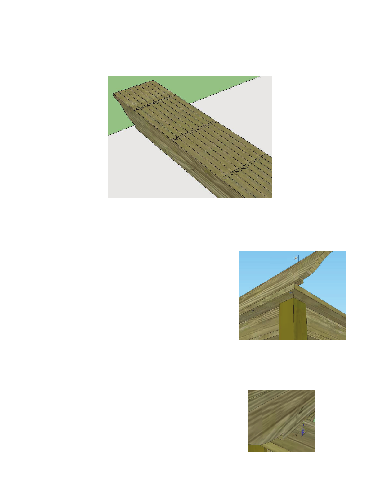
plates have marks for positioning the runners –these are usually set on the longest
dimension since runners span the short dimension. On square pergolas, the parts
are interchangeable, but the top plates with the markings need to be on opposing
sides. Be sure that the markings are facing up as shown below.
4. Join the Top Plate Pieces: The top plate
pieces must be joined together before
attaching them to the top of the posts or to the
beam. Place 3 ½” screws on an angle at the
corners as shown. There are no predrilled
holes. Since the screw is close to the end,
predrill a 1/8” hole.
5. Attach Top Plates: Position the assembled
top plates so that the seams in the corners are
centered across the corner posts. The top plate
will overhang the beams by about ½”- 1" on
the inside. Before attaching to the posts and to the top of the beam with 2 ½"
screws, make sure that the overhangs are the
same along the entire perimeter. Attach with
two screws at an angled cut into the top of the
wood posts and then along the beam approx.
every 24”.
Note: If the top plates are more than one
piece, attach at the place where they join with
four screws –two on either side of the seam.
Page | 6
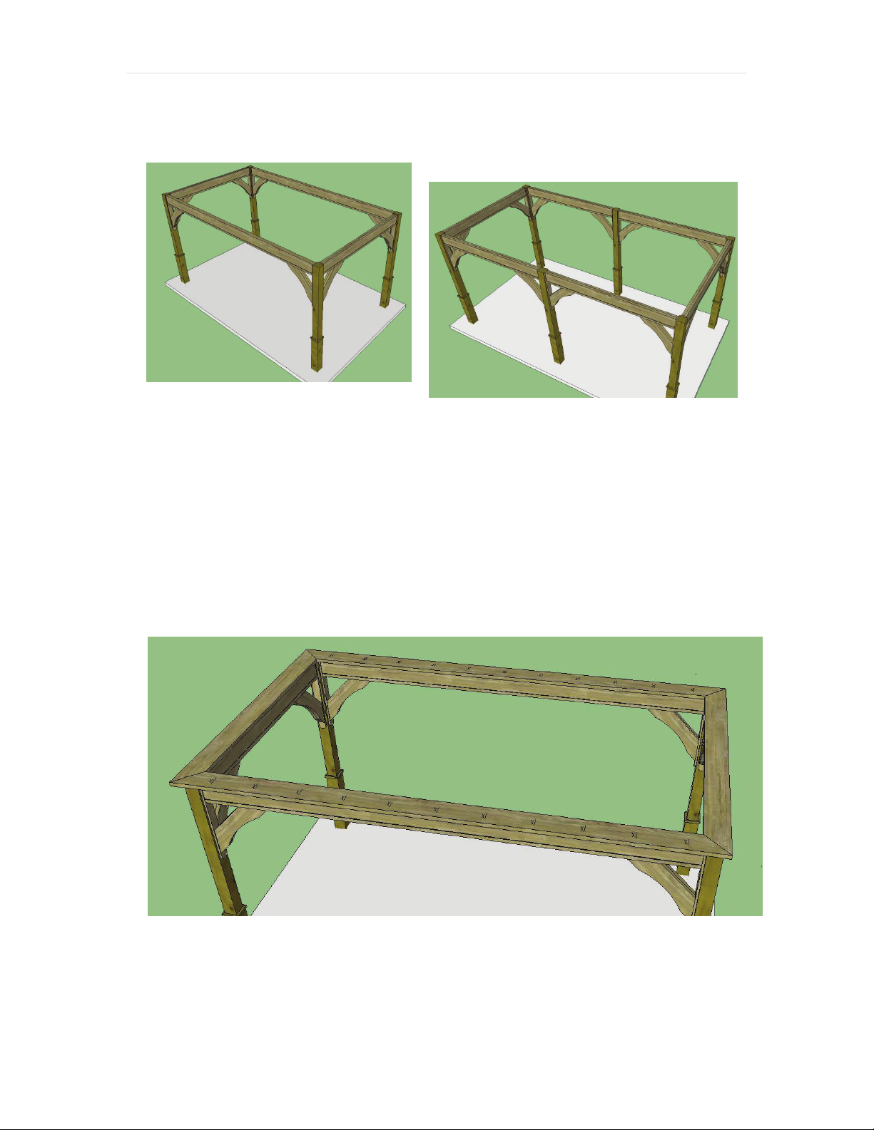
SECTION 3 –MAIN RUNNERS
The main runners are 2x6’s that have decorative cuts on both ends (unless a special
order). They have markings on the top for the top runners.
Note about spacing: Generally both the main and top runners are spaced 16” on center
unless you order other spacing. Since the first runner on each side will align with the
edge of the top plate as explained below, the spacing may need adjusted. This is done
during production and the marks made accordingly. Most importantly, the top runners
have notches that coincide with the calculations made. Never change the placement of the
main runners, or the top runners will not fit.
Since the top runners have notches, the overhangs cannot be adjusted later. These runner
notches are “symmetrical” but the markings will be backwards if not arranged correctly.
It is a good idea to lay all the runners down next to each other to make sure the lines and
X's are aligned. Make sure not to flip the direction when installing.
1. Set the First Main Runner: As discussed in the previous section, two
sides of the top plate are lined with marks to guide your runner placement.
Set the first 2x6 runner on the corresponding top plate marks at the outer
sides. The end runners are set about ¼” from the edge of the runners. Do
not flush the runner to the end of the top plate. Set the first runner. Next,
adjust the runner placement back and
forth until each overhang has an equal
measurement. (Hint: you can “split the
distance” to center the pergolas) For
example, if you have a measurement of
2” on one side and 1 ½” on the other
side, the difference is ½”. Moving the
runner just ¼” will center it. Once the
overhang measurement is the same,
Page | 6
SECTION 3 –MAIN RUNNERS
The main runners are 2x6’s that have decorative cuts on both ends (unless a special
order). They have markings on the top for the top runners.
Note about spacing: Generally both the main and top runners are spaced 16” on center
unless you order other spacing. Since the first runner on each side will align with the
edge of the top plate as explained below, the spacing may need adjusted. This is done
during production and the marks made accordingly. Most importantly, the top runners
have notches that coincide with the calculations made. Never change the placement of the
main runners, or the top runners will not fit.
Since the top runners have notches, the overhangs cannot be adjusted later. These runner
notches are “symmetrical” but the markings will be backwards if not arranged correctly.
It is a good idea to lay all the runners down next to each other to make sure the lines and
X's are aligned. Make sure not to flip the direction when installing.
1. Set the First Main Runner: As discussed in the previous section, two
sides of the top plate are lined with marks to guide your runner placement.
Set the first 2x6 runner on the corresponding top plate marks at the outer
sides. The end runners are set about ¼” from the edge of the runners. Do
not flush the runner to the end of the top plate. Set the first runner. Next,
adjust the runner placement back and
forth until each overhang has an equal
measurement. (Hint: you can “split the
distance” to center the pergolas) For
example, if you have a measurement of
2” on one side and 1 ½” on the other
side, the difference is ½”. Moving the
runner just ¼” will center it. Once the
overhang measurement is the same,