5
Introduction
Target Groups
Additional Technical Documentation
* Valid in Germany: Regulations for Occupational
Health and Safety on Construction Sites 30
(RAB 30).
** Instructions are given by the contractor himself
or a competent person selected by him.
Instructions for Use:
– LPS Climbing Device and Hydraulics
– Crane Eye BR-2 2.5 t
– Screen Adapter Stacking LPS 60
–Concrete Cones
Data Sheet: Anchor Bolt PERI 14/20 x 130
Flyer LPS Screen
Contractors
These Instructions for Assembly and
Use are designed for contractors who
use the PERI climbing system either for
assembling, modifying and disman-
tling purposes, or
use it or
have it used for formwork operations.
Competent person
(Construction Site Coordinator)
The Safety and Health Protection Coor-
dinator*
is appointed by the client,
must identify potential hazards during
the planning phase,
determines measures that provide
protection against risks,
creates a safety and health plan,
coordinates the protective measures
for the contractor and site personnel
so that they do not endanger each
other,
monitors compliance with the protec-
tive measures.
Competent person qualified to carry
out inspections
Due to the specialist knowledge gained
from professional training, work experi-
ence and recent professional activity,
the competent person qualified to carry
out inspections has a reliable under-
standing of safety-related issues and can
carry out inspections correctly. Depend-
ing on the complexity of the test to be
undertaken, e.g. scope of testing, type
of testing or the use of a certain measur-
ing device, a range of specialist knowl-
edge is necessary.
Qualified persons
The PERI climbing system may only be
assembled, modified or dismantled by
personnel who are suitably qualified to
do so. For the work to be carried out,
the qualified persons must have re-
ceived instructions** covering at least
the following points:
Explanation of the plan for the assem-
bly, modification or dismantling of the
climbing system in an understandable
form and language.
Description of measures in order to
safely assemble, modify or dismantle
the climbing system.
Designation of the preventive meas-
ures to avoid the risk of persons and
objects falling.
Designation of the safety precautions
in the event of changing weather con-
ditions that could adversely affect the
safety of the formwork system as well
as the persons concerned.
Details regarding the permissible
loads.
Description of any other risks that are
associated with the assembly, modifi-
cation or dismantling procedures.
In other countries, ensure that the
relevant national guidelines and
regulations in the respective cur-
rent version are complied with!
If no country-specific regulations
are available, it is recommended to
proceed according to German
guidelines and regulations.
A competent person must be pres-
ent on site during assembly opera-
tions.
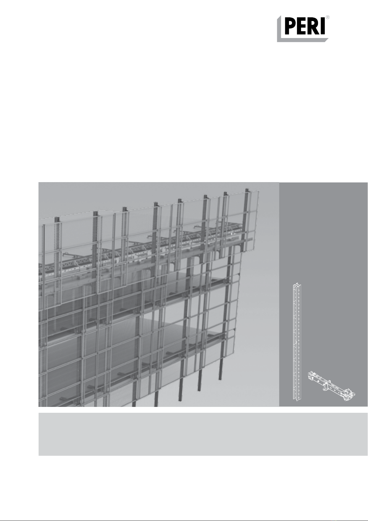
LPS Screen Lightweight Climbing Enclosure
Instructions for Assembly and Use – Standard Configuration