3
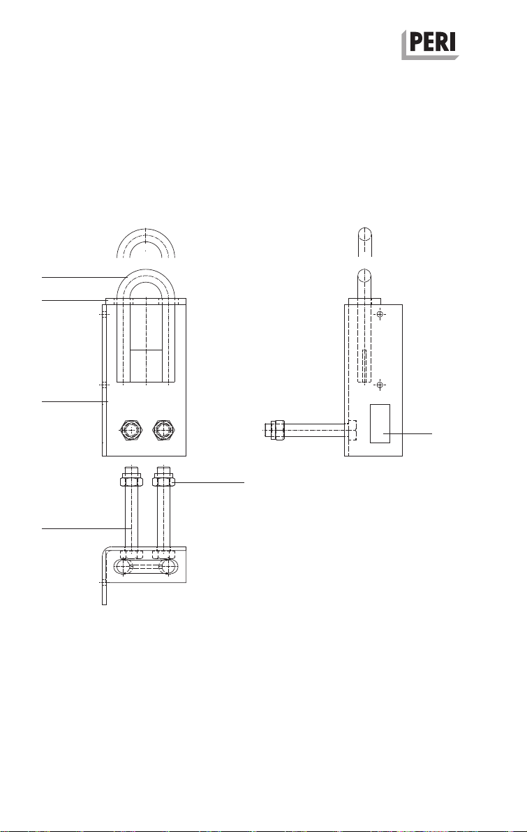
Platform Connection CB 160
Introduction
Translation of the Original Instructions for Use
Product-specific
The person who attaches the load to the
load-carrying equipment must be suffi-
ciently secured against falling. In all cas-
es, the load must be secured against
falling over and sliding!
Move loads only during the presence of
safe wind forces. Observe storm warn-
ings! Depending on the type of load and
the surface area subjected to wind at-
tack, the decision whether sufficient
safety is in place when moving the load
is taken at the time on the jobsite.
Use the specified load-carrying equip-
ment for moving loads. Before each lift-
ing procedure begins, check that the
load is securely connected to the lifting
gear.
Ensure loads are evenly balanced when
being picked up! Loads must be suffi-
ciently stable both in their form and
position so that the load does not move
during transportation!
Ensure that the load is in a safe and
secure position before releasing the
load-carrying equipment!
Always lift up or set down loads
smoothly without any jerking!
Safety Instructions
Before moving, remove or secure any
loose components!
Ensure that the steel wire rope or chains
are free of knots! Ensure that the lifting
chains of the load-carrying equipment
are not wrapped around the load to be
transported nor stretched over sharp
edges! Twisted chains must be straight-
ened!
Transporting persons on the load is pro-
hibited!
Components provided by the contractor
must meet site-related requirements
and comply with all applicable laws and
standards.
– Timber components: Strength Class
C24 for Solid Wood according to
EN 338.
– Scaffold tubes: galvanised steel tubing
with minimum dimensions
Ø 48.3 x 3.2 mm according to
EN12811-1:2003 4.2.1.2.
– Scaffold tube couplings according to
EN 74.