10
Safety Instructions
If the maximum permissible wind
speed has been exceeded, tempera-
tures are outside the scope of applica-
tion or after any extraordinary event
has taken place such as a fire or earth-
quake, the functionality and load-bear-
ing capacity of all safety components
as well as the supporting structure are
to be checked.
Safety components:
Visual checks are to be carried out
by authorised personnel at regular
intervals.
Before any climbing or assembly, a
functionality check is carried out by
qualified personnel.
If parts need to be replaced, only
PERI original components may be
used.
Repairs are only allowed to be car-
ried out by PERI qualified personnel.
In the case of overloading or recur-
rent damage, stop work operations
on and under the platforms, deter-
mine the cause and rectify.
Supporting structure:
A visual inspection is to be carried
out by authorised personnel before
initial use.
Only PERI original components are
to be used for repairs or replace-
ment.
In the case of overloading or recur-
rent damage, stop work operations
on and under the platforms, deter-
mine the cause and rectify.
Other components:
Repairs are carried out by authorised
personnel and the contractor/site
management is to be informed.
Determine the cause of any damage
that occurs on a recurring basis and
rectify.
Persons are not allowed to remain un-
der suspended loads. If work under
suspended loads cannot be avoided,
determine and apply all appropriate
measures. Avoid entering the area be-
tween suspended loads and the build-
ing.
Site personnel are forbidden to remain
in areas below where assembly work is
being carried out unless the area of risk
has been provided with sufficient pro-
tection against falling, overturning, slid-
ing or rolling objects and masses. The
area of risk is to be cordoned off.
Maintenance and repairs
The system components are to be in-
spected before each use to ensure that
they are in perfect condition and func-
tion correctly. Only materials in perfect
condition are to be used.
The units are to be inspected for signs
of damage at regular intervals by au-
thorised personnel. Dirt which affects
the functionality is to be removed im-
mediately. Damaged components are
to be inspected, removed and re-
placed.
System-Specific
Assembly work
The contractor must ensure that the
user has the appropriate and sufficient
number of tools, lifting equipment and
slings, suitable and sufficient space for
assembly and storage, as well as ade-
quate crane capacity at his disposal.
There is always the possibility of un-
foreseen risks arising during assembly
work. The level of risk is to be estimat-
ed according to each individual case
and, if necessary, measures are to be
taken to avoid or at least to minimise
the risk.
If anti-fall protection cannot be used or
has to be removed due to operational
reasons, safety equipment must be in-
stalled in its place in order to prevent or
arrest falls from any height. If the use
of fall arrest equipment is deemed to
be inappropriate, personal protection
equipment (PPE) can be used if suita-
ble fixing points are available.
Use a guide rope to ensure that assem-
bly units suspended from the crane are
fully under control when being moved.
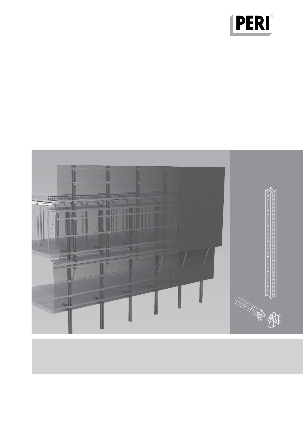
RCS P Climbing Protection Panel
Instructions for Assembly and Use – Standard Configuration