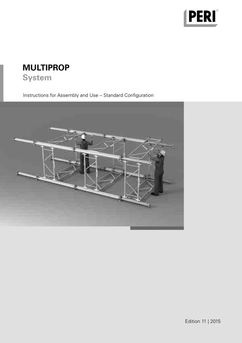
Peri VST Operator's manual

VST
Heavy-Duty Shoring Tower
Instructions for Assembly and Use – Standard Configuration
Edition 01 | 2017
VST Schwerlastturm_ex_794130.indb 2 06.03.17 11:56


VST Heavy-Duty Shoring Tower
Instructions for Assembly and Use – Standard Configuration
Content
Overview
Main components 1
Key 2
Presentational reference 2
Introduction
Target groups 3
Additional technical documentation 3
intended use 4
Instructions for Use 4
Cleaning and maintenance instructions 5
Safety instructions
Cross-system 6
System-specific 7
Storage and transportation 7
VST Heavy-Duty Shoring Tower
A1 Module overview
Overview of Module VST 8
Arrangement of the Bracing
Connectors VST 9
Module VST components 10
Additional components 11
A2 Module VST 125 12
A3 Module VST 175 13
A4 Module VST 275 14
A5 Module VST 375 15
A6 Module VST 525 16
A7 Module VST 775 17
A8 Module VST 1025 18
A9 Head Spindle Frame VST 19
A10 Head Spindle VST 100 20
A11 VST Tower Configuration 1 21
A12 VST Tower Configuration 2 22
A13 VST Tower Configuration 3 23
A14 VST Tower Configuration 4 24
A15 Arrangement of the Height Adjusts 25
A16 Assembly of two Cross Connectors VST
on the RCS / Bracing Connector VST 26
A17 Connecting Adapter VST-SRU 27
A18 VST Module with working platform 28
A19 VST Module with additional legs 30
A20 Hydraulic Unit VST 31
Assembly
B1 Operating states and loads
Operating state: mounting 32
Operating state: lowering and dismantling 32
B2 Assembly of the VST Leg
Preparation of the RCS Rail 33
Preparation of the Prop Base VST 48 33
Preparation of the Prop Connector VST 48 33
Prop Connector VST 48 34
Prop Base VST 48 35
Bracing Connector VST 36
Cross Connector VST 37
B3 Module Assembly
Horizontal Ledger VST 200 38
Diagonal Strut VST 39
B4 Head Spindle Frame
Mounting the Head Spindle Frame 40
Adjusting the spacer plates of the
Head Spindle VST 100 42
B5 Pre-assembly of the tower segments
Tower assembly with VST components 43
Tower assembly with SLS Spindles 46
B6 Working platform 49
Assembly
C1 Erecting the tower with VST components 51
C2 Erection of a single module 53
C3 Anchoring 57
Application
D1 Height adjustment (±140 mm)
Manual adjustment 58
Adjustment with the hydraulic cylinder 59
D2 Lowering procedure 60
Dismantling
E1 Dismantling
Preparation of the towers 61
Module preparation 62
Dismantling the tower 63
Dismantling the module 63
Work preparation
F1 Pre-dimensioning of the permissible
leg load at the head 64
F2 Load-bearing capacities 65
F3 Moving the module
Without Head Spindle Frame 66
With Head Spindle Frame 67
F4 Moving the towers
Without Head Spindle Frame 68
With Head Spindle Frame 69
F5 Combination Table 225 – 987.5 cm 70
F6 Combination Table 1000 – 1987.5 cm 72
F7 Combination Table 2000 – 2987.5 cm 74
F8 Combination Table 3000 – 4000 cm 76
VST Schwerlastturm_ex_794130.indb 1 06.03.17 11:56

1
VST Heavy-Duty Shoring Tower
Instructions for Assembly and Use – Standard Configuration
Overview
Main components
B2 Assembly of the VST Leg
B3 Module Assembly
B4 Head Spindle Frame
B5 Tower Assembly
D1 Height Adjustment Head Spindle VST (+/- 140 mm)
B3
B2
D1
B5
B4
VST Schwerlastturm_ex_794130.indb 1 06.03.17 11:56

2
VST Heavy-Duty Shoring Tower
Instructions for Assembly and Use – Standard Configuration
Dimension specifications
Dimensions are usually given in cm.
Other units of measure, e.g. m, are
shown in the illustrations.
Conventions
Instructions are numbered with:
1. ....., 2. ....., 3. .....
The result of an instruction is shown
by:
Position numbers are clearly provided
for the individual components and are
given in the drawing, e.g. 1, in the
text in brackets, for example (1).
Multiple position numbers, i.e. alter-
native components, are represented
with a slash, e.g. 1 / 2.
Overview
Key
Presentational reference
The illustration on the front cover of
these instructions is understood to be a
system representation only. The assem-
bly steps presented in these Instruc-
tions for Assembly and Use are shown
in the form of examples with only one
component size. They are valid accord-
ingly for all component sizes contained
in the standard configuration.
For a better understanding, detailed
illustrations are partly incomplete. The
safety installations which have possibly
not been featured in these detailed
drawings must nevertheless still be
available.
Arrows
Pictogram | Definition
Safety instructions
Note
Load-bearing point
Visual check
Tip
Misapplication
Correct application
Arrow representing an action.
VST Schwerlastturm_ex_794130.indb 2 06.03.17 11:56


3
VST Heavy-Duty Shoring Tower
Instructions for Assembly and Use – Standard Configuration
Introduction
Contractors
These Instructions for Assembly and
Use are designed for contractors who
use the scaffolding either for
assembling, modifying and disman-
tling operations, or
use it e.g. for concreting or,x
who have it used, e.g. for forming op-
erations.
Construction site coordinator
The Safety and Health Coordinator*
is appointed by the client,
must identify potential hazards during
the planning phase,
determines measures that provide
protection against risks,
creates a safety and health plan,
coordinates the protective measures
for the contractor and site personnel
so that they do not endanger each
other,
monitors compliance with the protec-
tive measures.
Target groups
Instructions for Assembly and Use
– PERI UP Rosett 72
Instructions for Use
– Pallets and Stacking Devices
– Hydraulic Head Spindle Device VST
Brochure
– VARIOKIT Engineering Construction Kit
Additional technical documentation
* Valid in Germany: Regulations for Occupa-
tional Health and Safety on Construction
Sites 30 (RAB 30).
** Instructions are given by the contractor him-
self or a qualified person selected by him.
Competent personnel
Due to the specialist knowledge gained
from professional training, work experi-
ence and recent professional activity,
the competent person has a reliable un-
derstanding of safety-related issues and
can correctly carry out inspections. De-
pending on the complexity of the test to
be undertaken, e.g. scope of testing,
type of testing or the use of a certain
measuring device, a range of specialist
knowledge is necessary.
Qualified specialists
The scaffolding may only be assembled,
modified or dismantled by personnel
who are suitably qualified to do so. For
the work to be carried out, the qualified
specialists must have received instruc-
tions** which contain at least the fol-
lowing points:
Explanation of the plan for the assem-
bly, modification or dismantling of the
scaffolding in an understandable form
and language.
Description of measures in order to
safely assemble, modify or dismantle
the scaffolding.
Designation of the preventive meas-
ures to avoid the risk of persons and
objects falling.
Designation of the safety precautions
in the event of changing weather con-
ditions which could adversely affect
the safety of the scaffolding as well
as the personnel concerned.
Details regarding the permissible
loads.
Description of any other risks that are
associated with the assembly, modifi-
cation or dismantling procedures.
In other countries, ensure that the
relevant national guidelines and
regulations in the respective cur-
rent version are complied with!
If no country-specific regulations
are available, it is recommended
to proceed according to German
rules and regulations.
VST Schwerlastturm_ex_794130.indb 3 06.03.17 11:56

4
VST Heavy-Duty Shoring Tower
Instructions for Assembly and Use – Standard Configuration
Intended use
Introduction
Product description
PERI products have been designed for
exclusive use in the industrial and com-
mercial sectors by qualified personnel
only.
The VST Heavy-Duty Shoring Tower can
transfer high loads from the formwork,
for in-situ concrete bridges and all tem-
porary support constructions for struc-
tural components.
The system can be used for all types of
supporting structures, with a permissi-
ble leg load of up to 700 kN (height-de-
pendent).
Through the use of the Hydraulic Head
Spindle Device VST, the system allows
adjustment of the head spindle under
full load.
The VST Heavy-Duty Shoring Tower is a
standard system which offers the possi-
bility to support bridge formwork on
girders or truss girders, prefabricated el-
ements and other temporary load situa-
tions.
Features
Main components are standardized
PERI components taken from the
VARIOKIT Engineering Construction Kit.
The base of the structure is formed by
two parallel legs consisting of RCS
Climbing Rails which are connected to
each other by means of Horizontal
Ledgers VST 200 and Diagonal Struts
VST at a centre distance of 2 m.
The Climbing Rail RCS is additionally
braced between the U-profiles with
Bracing Connectors VST at a distance of
max. 1.5 m upwards in order to increase
the bending stiffness in the weak axis.
The connection in the longitudinal direc-
tion of the module is carried out with
the Prop Base VST 48 and Prop Connec-
tor VST 48.
The module can be configured with
Horizontal Ladgers VST 200 and Diago-
nal Struts VST to form a tower.
The flexible adaptation for achieving the
required height can be carried out using
Modules VST 125 to VST 1025 in incre-
ments of 25 cm (see Section F Work
Preparation).
Fine adjustment of ± 140 mm is possi-
ble with the Head Spindle VST.
System dimensions
Axis dimension of the standard configu-
ration.
2 m x 2 m
Height: continuously adjustable
for other configurations, see Section
A12 to A15.
Permissible load-bearing capacity
Up to 700 kN (height-dependent) per
leg.
Instructions for Use
The use in a way not intended, deviating
from the standard configuration or the
intended use according to the Instruc-
tions for Assembly and Use, represents
a misapplication with a potential safety
risk, e.g. risk of falling.
Only PERI original components may be
used. The use of other products and
spare parts is not allowed.
Changes to PERI components are not
permitted.
VST Schwerlastturm_ex_794130.indb 4 06.03.17 11:56

5
VST Heavy-Duty Shoring Tower
Instructions for Assembly and Use – Standard Configuration
Introduction
Cleaning and maintenance instructions
In order to maintain the value and opera-
tional readiness of the PERI products
over the long term, clean the elements
after each use.
Some repair work may also be inevita-
ble due to the tough working conditions.
The following points should help to keep
cleaning and maintenance costs as low
as possible.
Do not clean powder-coated or galva-
nized components with steel brushes or
metal scrapers.
Mechanical components, e.g. spindles,
must be cleaned of dirt or concrete resi-
due before and after use, and then
greased with a suitable lubricant.
Provide suitable support for the compo-
nents during cleaning so that no unin-
tentional change in their position is pos-
sible.
Do not clean components suspended
on a crane.
Any repairs to PERI products are to be
carried out by qualified PERI personnel
only.
VST Schwerlastturm_ex_794130.indb 5 06.03.17 11:56

6
VST Heavy-Duty Shoring Tower
Instructions for Assembly and Use – Standard Configuration
Safety instructions
Cross-system
General
The contractor must ensure that the
Instructions for Assembly and Use sup-
plied by PERI are available at all times and
are understood by the site personnel.
These Instructions for Assembly and
Use can be used as the basis for creat-
ing a risk assessment. The risk assess-
ment is compiled by the contractor.
These Instructions for Assembly and
Use do not replace the risk assessment!
Always take into consideration and com-
ply with the safety instructions and per-
missible loads.
For the application and inspection of
PERI products, the current safety regu-
lations and guidelines must be observed
in the respective countries where they
are being used.
Materials and working areas are to be
inspected on a regular basis especially
before each use and assembly for:
signs of damage,
stability and
function.
Damaged components must be ex-
changed immediately on site and may
no longer be used.
Safety components are to be removed
only when they are no longer required.
Components provided by the contractor
must conform with the characteristics
required in these Instructions for
Assembly and Use as well as all valid
construction guidelines and standards.
Unless otherwise indicated, this applies
in particular to:
Timber components: Strength Class
C24 for Solid Wood according to EN
338.
Scaffold tubes: galvanised steel tubes
with minimum dimensions of Ø 48.3
x 3.2 mm according to EN 12811-
1:2003 4.2.1.2.
Scaffold tube couplings according to
EN 74.
Deviations from the standard configura-
tion are only permitted after a further
risk assessment has been carried out by
the contractor.
On the basis of this risk assessment,
appropriate measures for working and
operational safety as well as stability are
to be determined.
Corresponding proof of stability can be
provided by PERI on request if the risk
assessment and resulting measures to
be implemented are available.
Before and after exceptional occurrenc-
es that may have an adverse effect
regarding the safety of the formwork
system, the contractor must immediately
create an additional risk assessment,
with appropriate measures for ensur-
ing the stability of the scaffolding sys-
tem being carried out based on the
results,
and arrange for an extraordinary in-
spection by a competent person. The
aim of this inspection is to identify
and rectify any damage in good time
in order to guarantee the safe use of
the scaffolding system.
Exceptional occurrences can include:
accidents,
longer periods of non-use,
natural events, e.g. heavy rainfall,
icing, heavy snowfall, storms or
earthquakes.
Assembly, modification and disman-
tling work
Assembly, modification or dismantling
of scaffolds may only be carried out by
qualified specialists under the supervi-
sion of a competent person. The quali-
fied specialists must have received ap-
propriate training for the work to be car-
ried out with regard to specific risks and
dangers.
On the basis of the risk assessment and
Instructions for Assembly and Use, the
contractor must create installation in-
structions in order to ensure safe as-
sembly, modification and dismantling of
the scaffolding system.
Before initial use, the safe functioning of
the scaffold must be checked by a
competent person. The result of the
inspection must be documented in an
inspection record.
The contractor must ensure that the
personal protective equipment required
for the assembly, modification or dis-
mantling of the system, e.g.
safety helmet,
safety shoes,
safety gloves,
safety glasses,
is available and used as intended.
If personal protective equipment against
falling (PPE) is required or specified in
local regulations, the contractor must
determine appropriate attachment
points on the basis of the risk assess-
ment.
The personal protective equipment
against falling to be used is determined
by the contractor.
The contractor must
provide safe working areas for site
personnel which are to be reached
through the provision of safe access
ways. Areas of risk must be cordoned
off and clearly marked.
ensure the stability during all stages
of construction, in particular during
assembly, modification and disman-
tling of the formwork.
ensure and prove that all loads are
safely transferred.
Utilization
Every contractor who uses or allows the
scaffolding system or sections of the
scaffolding system to be used, has the
responsibility for ensuring that the
equipment is in good condition.
If the scaffolding system is used suc-
cessively or at the same time by several
contractors, the health and safety coor-
dinator must point out any possible mu-
tual hazards, and all work must be then
coordinated.
VST Schwerlastturm_ex_794130.indb 6 06.03.17 11:56
7
VST Heavy-Duty Shoring Tower
Instructions for Assembly and Use – Standard Configuration
Safety instructions
System-specific
The components are to be inspected for
signs of damage by authorised personnel
at regular intervals.
Dirt which affects the functionality is to
be removed immediately.
Damaged components are to be in-
spected, sorted out and replaced.
For information regarding the mainte-
nance of the Hydraulic Head Spindle
Device VST, see Instructions for Use.
Detailed project-specific static proof as
well as planning is required for each
time of use.
In addition, project-specific lifting and
lowering plans are to be created.
Lifting or lowering operations are only to
be performed when a competent person
has given the go-ahead and the upper
construction has sufficient load-bearing
capacity.
All screw connections are to be secured
with suitable nuts.
All fitting pin connections are to be se-
cured with cotter pins.
Storage and transportation
Store and transport components ensur-
ing that no unintentional change in their
position is possible. Detach lifting ac-
cessories and slings from the lowered
components only if they are in a stable
position and no unintentional change is
possible.
Do not throw off the components.
Use PERI load-bearing devices and lifting
gear as well as only those load-bearing
points provided on the component.
During the moving procedure,
ensure that components are picked
up and set down so that unintentional
falling over, falling apart, sliding, fall-
ing down or rolling is avoided.
no persons are allowed to remain un-
der the suspended load.
Pre-assembled modules and towers are
guided with ropes when moving them
by crane.
The access areas on the jobsite must be
free of obstacles and tripping hazards as
well as being slip-resistant.
For transportation, the surface must
have sufficient load-bearing capacity.
Use original PERI storage and transport
systems, e.g. crate pallets, pallets or
stacking devices.
VST Schwerlastturm_ex_794130.indb 7 06.03.17 11:56

8
VST Heavy-Duty Shoring Tower
Instructions for Assembly and Use – Standard Configuration
A1 Module overview
Overview of Module VST
Fig. A1.01
VST 1025VST 375 VST 525 VST 775
Head Spindle Frame VST 100VST 125 VST 175 VST 275
125
175
275
100
375
525
775
1025
VST Schwerlastturm_ex_794130.indb 8 06.03.17 11:56

9
VST Heavy-Duty Shoring Tower
Instructions for Assembly and Use – Standard Configuration
A1 Module overview
Arrangement of the Bracing
Connectors VST
Observe the assembly position of the
Prop Base VST and Prop Connector
VST.
(see Section B2)
Fig. A1.02
VST 1025VST 375 VST 525 VST 775
Head Spindle Frame VST 100VST 125 VST 175 VST 275
125
112.5
175
100 62.5
275
150 112.5
100
57.7
375
150 100 112.5
525
150 100 112.5150
775
150 150 100 112.5
100
150
150 150 112.5150
1025
150 150 150
VST Schwerlastturm_ex_794130.indb 9 06.03.17 11:56

10
VST Heavy-Duty Shoring Tower
Instructions for Assembly and Use – Standard Configuration
A1 Module overview
Module VST components
Table A1.01
Name Item no.
VST Legs consist of
Climbing Rail Profile RCS 98
Climbing Rail RCS 148
Climbing Rail RCS 248
Climbing Rail RCS 348
Climbing Rail RCS 498
Climbing Rail RCS 748
Climbing Rail RCS 998
The VST module consists of 2 VST Legs plus
Bracing Connector VST
Fitting Pin Ø21 x 120
Cotter Pin 4/1, galv.
Fitting Pin Ø26 x 120
Cotter Pin 5/1, galv.
Cross Connector VST
Bolt ISO 4014 M20 x 120-8.8, galv.
Nut ISO 7042 M20-8, galv.
Sleeve VST, galv.
Prop Base VST 48
Bolt ISO 4014 M30 x 130-10.9
Bolt ISO 4014 M24 x 140-10.9
Nut ISO 7042 M24-8, galv.
Prop Connector VST 48
Bolt ISO 4014 M24 x 80-8.8, galv.
Horizontal Ledger VST 200
Diagonal Strut VST 200/150
Diagonal Strut VST 200/100
Diagonal Strut VST 200/112.5
Diagonal Strut VST 200/62.5
117585
114166
109469
109470
109471
109472
109610
117411
104031
018060
111567
022230
117425
1139 9 4
781053
1174 92
1174 53
1174 52
114563
105032
1174 5 4
105416
117371
117379
117382
11738 5
11738 8
1
2
3
4
5
6
7
8
9
10
11
12
13
14
15
16
17
18
19
20
21
22
23
24
25
26
27
VST Schwerlastturm_ex_794130.indb 10 06.03.17 11:56

11
VST Heavy-Duty Shoring Tower
Instructions for Assembly and Use – Standard Configuration
A1 Module overview
Additional components
Name Item no.
28 Head Spindle VST 100 1174 65
28.1 Fork Head
28.2 Spindle Nut
28.3 Spindle Sleeve
29 Mounting Shaft VST 11737 7
30 Heavy-Duty Spindle SLS
31 Push-Pull Prop RS 1000, galv. 028990
32 Push-Pull Prop RS 1400, galv. 103800
33 Steel Waler Universal SRU U120
34 Adapter VST-SRU 123823
35 Bolt ISO 4014 M16 x 100-10.9 Special
36 Sleeve Ø 21 x 2, L = 29 mm Special
37 Cyl. Bolt ISO 4762 M20 x 150-8.8, galv. 11825 6
38 Connector UP-VST 117707
38.1 Retaining Lug
39 Bolt Ø 20 x 140, galv. 105400
40 PERI Wedge K, galv. 024250
41 Leg Connector VST 200/37.5 117712
42 Horizontal Connector VST 37.5 1176 9 6
43 Hydraulic Unit VST 75 117678
43.1 Hydraulic Hose
43.2 Hand Pump
43.3 Manometer
44 Height Adjust VST 12.5 117391
45 Height Adjust VST 25 1174 3 3
46.1 Standard UVR 300 100012
46.2 Standard UVR 150 102860
47 Ledger UH 150 400021
48 Steel Waler SRZ U100
49 Kicker AV
50 Tie Rod DW 15
51 Cam Nut DW 15, galv. 030130
52 Wingnut Pivot Plate DW 15, galv. 030370
53 Tie Rod DW 26
54 Counterplate DW 26 123825
55 Hex. Nut DW 26 SW 46/80, weldable 030970
Table A1.02
43.4 Hydraulic Cylinder
VST Schwerlastturm_ex_794130.indb 11 06.03.17 11:56

12
VST Heavy-Duty Shoring Tower
Instructions for Assembly and Use – Standard Configuration
A2 Module VST 125
Parts list for Module VST 125
Pos. Name Quantity
1Climbing Rail Profile RCS 98 4
9Fitting Pin Ø21 x 120 8
10 Cotter Pin 4/1, galv. 8
15 Nut ISO 7042 M20-8, galv. 12
17 Prop Base VST 2
18 Bolt ISO 4014 M30 x 130-10.9 12
19 Bolt ISO 4014 M24 x 140-10.9 12
20 Nut ISO 7042 M24-8, galv. 12
21 Prop Connector VST 48 2
23 Horizontal Ledger VST 200 2
26 Diagonal Strut VST 200/112.5 2
Connecting means are pre-assembled
in the VST components.
The total weight of a Module VST 125 is
370.20 kg.
Fig. A2.01
1
17
21
26
9
10
23
VST Schwerlastturm_ex_794130.indb 12 06.03.17 11:56

13
13
VST Heavy-Duty Shoring Tower
Instructions for Assembly and Use – Standard Configuration
A3 Module VST 175
Parts list for Module VST 175
Pos. Name Quantity
2Climbing Rail RCS 148 2
8 Bracing Connector VST 2
9Fitting Pin Ø21 x 120 18
10 Cotter Pin 4/1, galv. 18
11 Fitting Pin Ø26 x 120 4
12 Cotter Pin 5/1, galv. 4
13 Cross Connector VST 2
14 Bolt ISO 4014 M20 x 140-8.8 4
15 Nut ISO 7042 M20-8 16
16 Sleeve VST 2
17 Prop Base VST 2
18 Bolt ISO 4014 M20 x 130-10.9 12
19 Bolt ISO 4014 M24 x 140-10.9 12
20 Nut ISO 7042 M24-8 12
21 Prop Connector VST 48 2
23 Horizontal Ledger VST 200 3
25 Diagonal Strut VST 200/112.5 2
27 Diagonal Strut VST 200/62.5 2
Connecting means are pre-assembled
in the VST components.
The total weight of a Module VST 175 is
528.44 kg.
Fig. A3.01
2
17
21
23
25
11
8
27
9
10
VST Schwerlastturm_ex_794130.indb 13 06.03.17 11:56

14
13
VST Heavy-Duty Shoring Tower
Instructions for Assembly and Use – Standard Configuration
A4 Module VST 275
Parts list for Module VST 275
Pos. Name Quantity
3Climbing Rail RCS 248 2
8 Bracing Connector VST 2
9Fitting Pin Ø 21 x 120 18
10 Cotter Pin 4/1, galv. 18
11 Fitting Pin Ø26 x 120 4
12 Cotter Pin 5/1, galv. 4
13 Cross Connector VST 2
14 Bolt ISO 4014 M20 x 140-8.8 4
15 Nut ISO 7042 M20-8 16
16 Sleeve VST 2
17 Prop Base VST 2
18 Bolt ISO 4014 M20 x 130-10.9 12
19 Bolt ISO 4014 M24 x 140-10.9 12
20 Nut ISO 7042 M24-8 12
21 Prop Connector VST 48 2
23 Horizontal Ledger VST 200 3
24 Diagonal Strut VST 200/150 2
26 Diagonal Strut VST 200/112.5 2
Connecting means are pre-assembled
in the VST components.
The total weight of a Module VST 275 is
644.02 kg.
Fig. A4.01
3
9
17
21
23
24
11
8
26
9
10
VST Schwerlastturm_ex_794130.indb 14 06.03.17 11:56

15
VST Heavy-Duty Shoring Tower
Instructions for Assembly and Use – Standard Configuration
A5 Module VST 375
Parts list for Module VST 375
Pos. Name Quantity
4Climbing Rail RCS 348 2
8 Bracing Connector VST 4
9Fitting Pin Ø 21 x 120 28
10 Cotter Pin 4/1, galv. 28
11 Fitting Pin Ø 26 x 120 8
12 Cotter Pin 5/1, galv. 8
13 Cross Connector VST 4
14 Bolt ISO 4014 M20 x 120-8.8 8
15 Nut ISO 7042 M20-8 20
16 Sleeve VST 4
17 Prop Base VST 2
18 Bolt ISO 4014 M20 x 130-10.9 12
19 Bolt ISO 4014 M24 x 140-10.9 12
20 Nut ISO 7042 M24-8 12
21 Prop Connector VST 48 2
23 Horizontal Ledger VST 200 4
24 Diagonal Strut VST 200/150 2
25 Diagonal Strut VST 200/100 2
26 Diagonal Strut VST 200/112.5 2
Connecting means are pre-assembled
in the VST components.
The total weight of a Module VST 375 is
852.64 kg.
Fig. A5.01
4
9
17
23
24
8
11
13
26
25
21
9
10
VST Schwerlastturm_ex_794130.indb 15 06.03.17 11:56

16
VST Heavy-Duty Shoring Tower
Instructions for Assembly and Use – Standard Configuration
A6 Module VST 525
Parts list for Module VST 525
Pos. Name Quantity
5Climbing Rail RCS 498 2
8 Bracing Connector VST 6
9Fitting Pin Ø 21 x 120 38
10 Cotter Pin 4/1, galv. 38
11 Fitting Pin Ø26 x 120 12
12 Cotter Pin 5/1, galv. 12
13 Cross Connector VST 6
14 Bolt ISO 4014 M20 x 140-8.8 12
15 Nut ISO 7042 M20-8 24
16 Sleeve VST 6
17 Prop Base VST 2
18 Bolt ISO 4014 M20 x 130-10.9 12
19 Bolt ISO 4014 M24 x 140-10.9 12
20 Nut ISO 7042 M24-8 12
21 Prop Connector VST 48 2
23 Horizontal Ledger VST 200 5
24 Diagonal Strut VST 200/150 4
25 Diagonal Strut VST 200/100 2
26 Diagonal Strut VST 200/112.5 2
Connecting means are pre-assembled
in the VST components.
The total weight of a Module VST 525 is
1123.6 6 kg.
Fig. A6.01
5
17
21
23
24
13
8
26
25
9
11
VST Schwerlastturm_ex_794130.indb 16 06.03.17 11:56
Table of contents
Other Peri Construction Equipment manuals

Peri
Peri CB 160 Operating and installation instructions

Peri
Peri CB 160 Operator's manual

Peri
Peri Trio Operator's manual

Peri
Peri SKYMAX Operator's manual

Peri
Peri RCS-2 Guide

Peri
Peri LPS Screen Operator's manual

Peri
Peri RCS-2 Guide

Peri
Peri RCS P Operator's manual

Peri
Peri SKYDECK Operator's manual

Peri
Peri SB Brace Frame Operator's manual