BodiLink Lateral Trunk Support Operation Manual
3
IMPORTANT SAFETY INFORMATION, CONTINUED
WARNINGS: Installation, Interference, Use
- Unless otherwise specied, fasteners should be
tightened to 9.6 Nm (85 lb-in).
- Ensure that the product does not interfere with any other
wheelchair components. Interference could jeopardize
eectiveness and user safety and cause damage. After
installation, slowly articulate the full range of power/
recline / tilt, watching closely to make sure there is no
interference.
- DO NOT modify this product. Doing so will void its
warranty and may lead to personal injury or alter the
eectiveness of the product by increasing the risk factors
for skin breakdown and/or instability.
- Installing alternate parts to your wheelchair may change
the structure and function of the equipment. To ensure
stability during use, assess the need for additional safety
features on the wheelchair, such as anti-tip bars or other
available options.
- Use caution when installing, adjusting, or removing
hardware, to avoid pinching or trapping ngers in
openings.
- Do not expose the product or components to high
heat, open ames or hot ashes. Testing or certication
claims, including for ammability, may no longer apply
to this device when it is combined with other products
or materials. Check testing and certication claims for all
products used in combination with this device.
- Metal components may become hot if exposed to high
temperatures or cold if exposed to low temperatures.
Take appropriate precautions, especially when the
product will contact unprotected skin.
- Avoid sharp objects.
- Protect the product from blunt force shocks that may
cause damage and/or breakage.
- Always use the cover and base with any inserts as a
complete assembly. Never use a cover other than one
intended for your specic product and size.
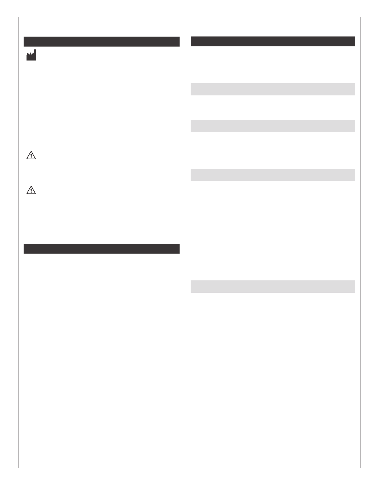
- After hardware and pad positioning, make sure that the
gear teeth* on all link joints are properly aligned and
engaged before nal tightening. Failing to do so could
cause wear on the teeth, leading to parts slipping out of
adjustment or hardware failure.
- Adding additional links to the hardware may reduce the
overall strength.
*Gear Teeth Alignment
Warnings: Motor Vehicle Transportation
- Failure to pay attention to these warnings could result
in severe injury to the individual in the wheelchair or to
others.
- Whenever possible, transfer out of your wheelchair
installed with BodiLink Supports and into a manufacturer-
installed vehicle seat, and use the vehicle’s crash-tested
occupant restraint system.
- Children weighing less than 48½ lb. (22 kg) must be
transferred into an appropriate child-restraint system
intended for use in motor vehicles.
- ALWAYS store BodiLink Supports safely during transport
to avoid damage.
- If a BodiLink Support has been involved in an accident
during transport, see the “Inspection” section in this
manual.
- The motor vehicle safety information in this operation
manual applies to BodiLink Supports a) only when
correctly and securely installed, as instructed in this
manual; b) only with a wheelchair that complies with
the performance requirements of ISO 7176-19 and
that is installed, used, and maintained according to the
wheelchair manufacturer’s instructions.
- The individual should be seated in an upright position and
the wheelchair should face forward during transportation
in a motor vehicle. BodiLink Supports have only been
crash tested on a wheelchair in the forward-facing
position, per the test information provided in this
operation manual.
- The wheelchair with a BodiLink Support must be used
with an eective wheelchair securement system and a
properly positioned, crash-tested pelvic- and shoulder-
belt restraint, or a Wheelchair Tiedown and Occupant
Restraint System (WTORS), following the manufacturer’s
instructions.
The Comfort Company seating system with a back support
and accessories, including BodiLink Supports, installed on
a surrogate wheelchair frame, has been dynamically tested
by a third-party testing facility for use in a motor vehicle,
and meets all applicable performance criteria in Section 5.1
of ANSI/RESNA WC-4:2012 Section 20 “Wheelchair Seating
Systems for Use in Motor Vehicles” and in 5.1 of ISO 16840-4
when tested with a surrogate seat.