Permobil Halsa User manual

Hälsa Bed
Owner’s Manual

Hälsa Bed Owner’s Manual
Version 2.0 August 2018 © Permobil 2018
This document may not be reproduced, copied or used for purposes
other than its intended use without the prior written consent of Permobil.
This manual includes installation instructions as well as important safety and
maintenance information for your Hälsa Bed.
All information, pictures, illustrations and specifications are based upon the product
information available at the time this manual was created.
The information in this document is subject to change without notice.
ALL RIGHTS RESERVED
Technical and Customer Support
In the event of any issues, contact your dealer or call
Permobil Canada at 800-265-9830.
Be prepared to provide the bed serial number.
Spare parts and accessories may be ordered through your dealer.
Permobil Canada
2215/2221 46e Avenue •Lachine, QC H8T 3C9
Tel: 800-265-9830 •Fax: 877-636-8944 •Email: sales.ca@permobil.com
www.permobil.ca

Hälsa Bed Owner’s Manual
Table of Contents
Introduction 1
Design and Functions ...............................................................................................................................1
Specifications ...............................................................................................................................................2
Safety Precautions .....................................................................................................................................2
Assembly 3
Overview........................................................................................................................................................3
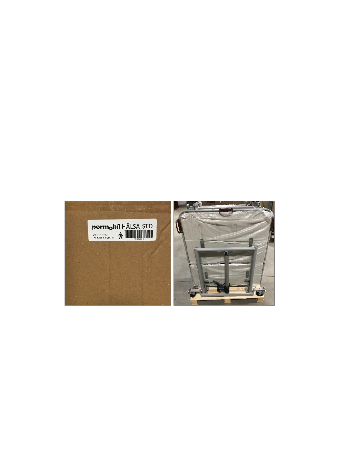
Inspection before unpacking .................................................................................................................3
Damage during transport ...................................................................................................................4
Incorrect shipment ................................................................................................................................4
1 – Unpack the bed ...................................................................................................................................5
2 – Assemble the frame ...........................................................................................................................8
Remove the platform ........................................................................................................................ 12
3 – Connect the electrical systems ................................................................................................... 13
3.1 - Access the central motor ....................................................................................................... 14
3.2 - Temporarily remove the cable separator ......................................................................... 15
3.3 - Connect the foot hi-low motor ........................................................................................... 16
3.4 - Connect the head hi-low motor .......................................................................................... 17
3.5 - Connect the power cord and hand pendant .................................................................. 17
3.6 - Connect the battery backup ................................................................................................. 18
3.7 - Connect the leg/knee motor ................................................................................................ 19
3.8 - Cut remaining cable ties on bed frame ............................................................................ 20
3.9 - Test the connections ............................................................................................................... 21
3.10 - Replace the cable separator ............................................................................................... 22
4 – Install optional side rails................................................................................................................ 23
Install full side rails ............................................................................................................................. 23

Hälsa Bed Owner’s Manual
Install half side rails ............................................................................................................................ 25
5 – Install the platform .......................................................................................................................... 27
6 – Install the headboard and footboard ....................................................................................... 28
7 – Finish the assembly ......................................................................................................................... 31
Install bumpers .................................................................................................................................... 31
Tidy wires ............................................................................................................................................... 31
Prepare to install the mattress ....................................................................................................... 31
Usage 32
Inspect the bed before use ................................................................................................................. 32
Move the bed into different positions ............................................................................................ 33
Safe operation .......................................................................................................................................... 33
Moving the bed ................................................................................................................................... 33
Using side rails ..................................................................................................................................... 34
User safety ............................................................................................................................................. 34
Electrical safety .................................................................................................................................... 34
Maintenance ............................................................................................................................................. 35
Cleaning ................................................................................................................................................. 35
Regular inspection .............................................................................................................................. 35
Warranty ..................................................................................................................................................... 35
Returns ........................................................................................................................................................ 36

Permobil Hälsa Bed Owner’s Manual Design and Functions
www.permobil.ca 1
Introduction
Design and Functions
The Hälsa Bed is an electric adjustable bed with Trendelenburg & reverse Trendelenburg
capabilities.
The Hälsa Bed includes
• frame
• platform
• headboard and
footboard
• electrical systems
• hand controller
• 4 casters
• optional full or
partial side rails
(available at an
additional cost)
The frame and platform
disassemble into 4 parts
for easy assembly,
transport and storage.
HEADBOARD
PLATFORM
OPTIONAL
SIDE RAILS
HAND
CONTROLLER
ELECTRICAL SYSTEM
(UNDER BED)
FRAME
FOOTBOARD
CASTERS

Permobil Hälsa Bed Owner’s Manual Specifications
www.permobil.ca 2
Specifications
Weight capacity: The maximum weight capacity for the Hälsa Bed is 170 kg (375 lbs)
Weight: The Hälsa Bed weighs approximately 99 kg (265 lb) but can vary depending on
the options and accessories included
Overall dimensions: 223 cm ±10 mm L x 96 cm ±10 mm W
(88" ± 0.5" L x 38" ± 0.5" W)
Platform dimensions: 201 cm ±10 mm L x 90 cm ±10 mm W
(79" ± 0.5" L x 36" ± 0.5" W)
Minimum height: 24.5 cm ±10 mm (10" ± 0.5")]
Maximum height: 64 cm ±10 mm (25" ± 0.5")
Electrical: 120V, 60 Hz
Additional electrical specifications are indicated on the motor.
Safety Precautions
Read and follow all instructions and warnings in this manual before assembling and using
your electric bed. Incorrect assembly or use may injure the user or damage the bed.
Permobil is not responsible for personal injuries or property damage resulting from any
personʼs failure to follow the warnings and instructions in this manual. Permobil is not
responsible for injuries or damage resulting from failure to exercise good judgment.
The Hälsa Bed is not for pediatric use.
The final selection and purchasing decision about the type of electric bed to be used is the
responsibility of the user and his or her healthcare professional. Permobil is not
responsible for inappropriate selections of models or features or improper mountings on
the bed.
The maximum weight capacity for this bed is in the specifications section listed above.
Operation of the bed by users who exceed the maximum allowable weight can lead to
personal injury and property damage, including damage to the bed, as well as voiding any
warranty applicable to the bed.
The Hälsa Bed should not be used in the presence of flammable anesthetic gas mixed
with air, oxygen, or nitrogen oxide.

Permobil Hälsa Bed Owner’s Manual Overview
www.permobil.ca 3
Assembly
Overview
The Hälsa Bed is designed for easy assembly, disassembly, and transport.
Assembly can be accomplished by one person.
The general steps are as follows:
1 - Unpack the bed
2 - Assemble the frame
3 - Connect the electrical systems
4 - Install optional side rails, if using
5 - Install the platform
6 - Install the headboard and footboard
7 - Finish the assembly
Instructions for each of these steps is included in this manual.
Tools required: cable tie snippers, flat head screwdriver, Allen key (for optional full side rails
only), ratchet set (for optional half side rails only), Phillips head screwdriver
Inspection before unpacking
Your bed will arrive in 2-3 separate boxes, depending on whether or not you ordered side rails:
• Frame and platform, including motors and electrical components
• Headboard and footboard
• Optional side or full rails

Permobil Hälsa Bed Owner’s Manual Inspection before unpacking
www.permobil.ca 4
Damage during transport
Check your shipment to ensure that the Hälsa Bed or accessories have not suffered transport
damage. It is the responsibility of the receiver to check the shipment. If damaged, there is a risk
that the bed and its accessories can no longer be used safely and securely. Contact your dealer or
Permobil for further information.
If there is any damage, it must be indicated on the bill of lading. Permobil must be informed of
the situation within 24 hours of receipt of goods so that the carrier can be notified as soon as
possible. If Permobil is not informed within 24 hours or the damages are not indicated on the bill
of lading, the customer may have to pay all the costs incurred to replace or repair the damaged
product.
Incorrect shipment
If a Permobil product does not match the original order invoice, the problem must be
communicated to Permobil within 48 hours of the time of delivery. Then, actions necessary to
correct the situation will be at Permobil’s expense and will be made as soon as possible,
following the notification of the incorrect shipment.

Permobil Hälsa Bed Owner’s Manual 1 – Unpack the bed
www.permobil.ca 5
1 – Unpack the bed
The frame and platform are shipped in 4 pieces in the same box:
• Head support
• Foot support
• Head frame with motors and electrical systems attached
• Foot frame with motors and electrical systems attached
The head support and frame are longer than the foot support and frame, so you can easily tell
them apart. All pieces are secured to a bracket on the packing skid.
STEPS
1 - Identify the box that contains the bed.
2 - Remove the outer box by slowly lifting it up. A wooden protective insert could fall out if
the cardboard box is not removed carefully.
Note that the bed is attached to a bracket on the packing skid.

Permobil Hälsa Bed Owner’s Manual 1 – Unpack the bed
www.permobil.ca 6
3 - From the side of the packing skid, unscrew and remove the 2 red-handled knobs on each
side of the head and foot frame assemblies to unfasten the bed from the packing bracket.
There are 4 knobs total (2 on each side).
4 - Lift the head and foot frame assemblies off the packing support and move it aside.
5 - Remove the wing nut and bolt securing the packing bracket to the skid.
PACKING BRACKET
REMOVE WING
NUT AND BOLT
UNSCREW
AND
REMOVE
LIFT THE FRAME
ASSEMBLIES UP OFF
THE PACKING BRACKET

Permobil Hälsa Bed Owner’s Manual 1 – Unpack the bed
www.permobil.ca 7
6 - The head and foot supports are still attached to the packing bracket. Shift the head
support higher and the foot support lower so there is clearance off the skid. Undo the
locking pins on each side of the foot frame to release the foot frame from the packing
bracket.
7 - Repeat to release the head support from the bracket.
Packing Materials
After removing the 4 bed pieces, you will
have a skid, 4 locking knobs and 2 bolts
with wing nuts that are not needed to
assemble the bed. These items are for
packing and transport. It is recommended
to store these packing materials so that
you can securely store and transport the
bed if necessary.
LOCKING PIN
LOCKING
PIN
SHIFT THE FOOT
SUPPORT OFF THE SKID
FOR CLEARANCE
PACKING
MATERIALS

Permobil Hälsa Bed Owner’s Manual 2 – Assemble the frame
www.permobil.ca 8
2 – Assemble the frame
The Hälsa Bed frame is provided in 4 pieces. You will lie the head and foot supports on the floor
and then attach the head frame assembly to the head support and the foot frame assembly to the
foot support. Casters come installed on the frame.
STEPS
1 - Lock casters as necessary.
2 - Lie the head and foot supports down about 91 cm (3') apart.
PUSH DOWN TO
LOCK CASTER
NOTE THE
LOCATION OF
SLOTS ON HEAD
SUPPORT
NOTE THE
LOCATION OF
SLOTS ON FOOT
SUPPORT
SUPPORT
HEAD
SUPPORT
FOOT
SUPPORT

Permobil Hälsa Bed Owner’s Manual 2 – Assemble the frame
www.permobil.ca 9
3 - Place the head frame assembly above the head support, lining up the lock pins on the
head frame assembly with the slots on the head support.
4 - Hook and join the head frame assembly to the head support by sliding the lock pins on
the head frame assembly into the slots on the head support. Ensure that each lock pin is in
position at the end of the slot as shown below. Rotate the red locking knob to secure the
lock pin in place. Repeat on the other side of the head frame. Ensure that the lock pins are
secured in place on each side.
5 - Repeat steps 3 and 4 to secure the foot frame assembly to the foot support.
LOCK PIN
SLOT
ENSURE THAT THE
LOCK PIN IS AT THE
END OF THE SLOT
ROTATE THE LOCKING
KNOB TO SECURE THE
LOCK PIN IN PLACE
LOCK PINS ON HEAD FRAME
ASSEMBLY LOCK INTO
SLOTS ON HEAD SUPPORT
HEAD FRAME
ASSEMBLY

Permobil Hälsa Bed Owner’s Manual 2 – Assemble the frame
www.permobil.ca 10
6 - Place a foot on the head support to hold it steady and then pull down on the head frame
assembly to lay it down on the ground.
7 - Repeat with the foot end so that the head frame assembly and foot frame assembly are on
the ground in a bed shape.
PULL DOWN ON
THE FRAME
ASSEMBLY SO
THAT YOU CAN
LAY IT ON THE
GROUND

Permobil Hälsa Bed Owner’s Manual 2 – Assemble the frame
www.permobil.ca 11
8 - Lift the head and foot decks so that you can align the locking inserts on the foot deck to
the locking slots on the head deck.
9 - Ensure that each locking insert is fully in the corresponding locking slot.
10 - Rotate the red knobs clockwise to lock the decks together.
11 - Ensure that the decks are securely locked together.
SLIDE THE LOCKING
INSERT INTO
THE LOCKING SLOT
NOT YET FULLY
CONNECTED
FULLY CONNECTED.
TURN THE RED KNOB
CLOCKWISE TO LOCK

Permobil Hälsa Bed Owner’s Manual 2 – Assemble the frame
www.permobil.ca 12
Remove the platform
To access the electrical connections and motors, you must first temporarily move the platform
out of the way.
Tool required: cable tie snipper
STEPS
1 - Remove all cable ties from the 4 platform segments. Note that one of the platform
segments is cable tied underneath the frame.
2 - Lift the 4 platform segments off the frame, and put them aside.

Permobil Hälsa Bed Owner’s Manual 3 – Connect the electrical systems
www.permobil.ca 13
3 – Connect the electrical systems
To connect the electrical systems, 5 cables must be connected to the central motor. All
connections (except the battery backup) are color-coded.
Overview
1 - Access the central motor
2 - Remove the cable separator
3 - Connect the foot hi-low motor - blue
4 - Connect the head hi-low motor - green
5 - Plug in the power cord
6 - Connect the hand pendant - white
7 - Connect the battery backup
8 - Connect the leg/knee motor – red
9 - Cut remaining ties on frame
10 - Test electrical systems
11 - Replace cable separator
NOTE:The back motor cable (yellow) is already connected.
CENTRAL
MOTOR
FOOT
HI-LOW
MOTOR
HEAD
HI-LOW
MOTOR
BATTERY
BACKUP
BACK
MOTOR
LEG/KNEE
MOTOR
HAND
PENDANT

Permobil Hälsa Bed Owner’s Manual 3 – Connect the electrical systems
www.permobil.ca 14
3.1 - Access the central motor
Cut the cable tie holding the hand pendant and power cord to the central motor.

Permobil Hälsa Bed Owner’s Manual 3 – Connect the electrical systems
www.permobil.ca 15
3.2 - Temporarily remove the cable separator
To make the electrical connections, you must temporarily remove the cable separator from the
bed’s central motor. The cable separator is snapped in on each end of the underside of the motor.
Overview
Tool required: flat head screwdriver
STEPS
1 - Locate where the cable separator is connected on one side of the motor.
2 - While pushing in with a flat head screwdriver, push down until you can swing the cable
separator out.
3 - Repeat on the other side of the motor so you can remove the cable separator completely.
PUSH IN WITH A
FLAT HEAD
SCREWDRIVER
PUSH
DOWN
WHERE CABLE SEPARATOR IS
SNAPPED IN UNDERNEATH
(LEFT SIDE IS UNDERNEATH)
SWING
OUT
CABLE
SEPARATOR

Permobil Hälsa Bed Owner’s Manual 3 – Connect the electrical systems
www.permobil.ca 16
3.3 - Connect the foot hi-low motor
STEPS
1 - Remove the packaging from the foot hi-low motor.
2 - Run the green color-coded cable under the frame and through the first hook.
3 - Extend the coiled cord as needed to reach the central motor.
4 - Run the cable ABOVE the back motor and then through the second hook.
5 - Plug the green plug into the green location on the central motor, making sure that the
arrow is on top.
RUN THE GREEN
CABLE THROUGH
FIRST HOOK
UNCOIL AS
NEEDED
RUN THE GREEN CABLE
ABOVE THE BACK MOTOR
AND THEN THROUGH THE
SECOND HOOK
MAKE SURE
THE ARROW
IS FACING UP
Other manuals for Halsa
1
Table of contents
Other Permobil Medical Equipment manuals
Popular Medical Equipment manuals by other brands

Otto Bock
Otto Bock Malleo Immobil Walker high Instructions for use

Siemens
Siemens MAMMOMAT Novation DR Parts Replacement

GE
GE Vivid E9 Service manual

Mopec
Mopec HB Series Refrence Manual

Mercado Medic
Mercado Medic REAL 9200 TWIN Instructions for use and care

Dräger
Dräger Fabius GS SW 3.n Reprocessing guide