Permobil Halsa Plus Bed User manual

Hälsa Plus Bed
Owner’s Manual

Hälsa Plus Bed Owner’s Manual
Version 2.0 August 2018 © Permobil 2018
This document may not be reproduced, copied or used for purposes
other than its intended use without the prior written consent of Permobil.
This manual includes installation instructions as well as important safety and
maintenance information for your Hälsa Plus Bed.
All information, pictures, illustrations and specifications are based upon the product
information available at the time this manual was created.
The information in this document is subject to change without notice.
ALL RIGHTS RESERVED
Technical and Customer Support
In the event of any issues, contact your dealer or call
Permobil Canada at 800-265-9830.
Be prepared to provide the bed serial number.
Spare parts and accessories may be ordered through your dealer.
Permobil Canada
2215/2221 46e Avenue •Lachine, QC H8T 3C9
Tel: 800-265-9830 •Fax: 877-636-8944 •Email: s[email protected]
www.permobil.ca

Hälsa Plus Bed Owner’s Manual
Table of Contents
Introduction 1
Design and Functions ...............................................................................................................................1
Specifications ...............................................................................................................................................2
Safety Precautions .....................................................................................................................................2
Assembly 3
Overview........................................................................................................................................................3
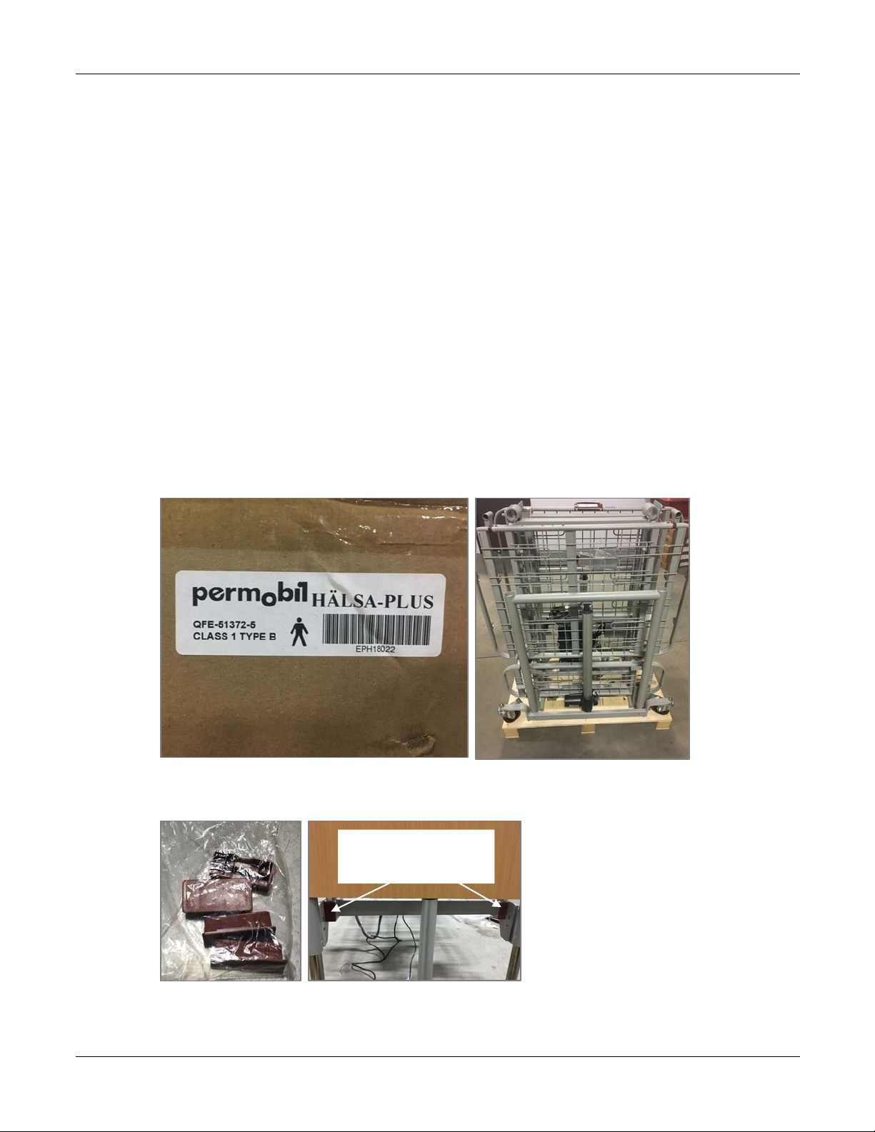
Inspection before unpacking .................................................................................................................3
Damage during transport ...................................................................................................................4
Incorrect shipment ................................................................................................................................4
1 – Unpack the bed ...................................................................................................................................5
2 – Assemble the platform .....................................................................................................................8
Remove cable ties ............................................................................................................................... 12
3 – Connect the electrical systems ................................................................................................... 13
3.1 - Connect the head and foot motors ................................................................................... 14
3.2 - Connect the power cord ........................................................................................................ 14
3.3 - Connect the lever bar and lever bar support ................................................................. 15
3.4 - Connect the battery backup ................................................................................................. 17
3.5 - Connect the leg/knee motor ................................................................................................ 18
3.6 - Run wires through hooks under bed................................................................................. 18
3.7 - Test the connections ............................................................................................................... 19
4 – Install optional half side rails ....................................................................................................... 20
5 – Install the headboard and footboard ....................................................................................... 22
6 – Finish the assembly ......................................................................................................................... 25
6.1 - Install bumpers .......................................................................................................................... 25
6.2 - Tidy wires ..................................................................................................................................... 25

Hälsa Plus Bed Owner’s Manual
6.3 - Prepare to install the mattress ............................................................................................. 25
6.4 - Expand the width of the platform ...................................................................................... 26
Usage 28
Inspect the bed before use ................................................................................................................. 28
Move the bed into different positions ............................................................................................ 29
Safe operation .......................................................................................................................................... 29
Moving the bed ................................................................................................................................... 29
Using side rails ..................................................................................................................................... 30
User safety ............................................................................................................................................. 30
Electrical safety .................................................................................................................................... 30
Maintenance ............................................................................................................................................. 31
Cleaning ................................................................................................................................................. 31
Regular inspection .............................................................................................................................. 31
Warranty ..................................................................................................................................................... 31
Returns ........................................................................................................................................................ 32

Permobil Hälsa Plus Bed Owner’s Manual Design and Functions
www.permobil.ca 1
Introduction
Design and Functions
The Hälsa Plus Bed is an electric adjustable bed with Trendelenburg & reverse
Trendelenburg capabilities.
The Hälsa Plus Bed includes
• platform
• headboard and footboard
• electrical systems
• hand controller
• 4 casters
• optional partial side rails (available at an additional cost)
The platform disassembles into 4 parts for easy assembly, transport and storage.
HEADBOARD
OPTIONAL
SIDE RAILS
HAND
CONTROLLER
ELECTRICAL SYSTEM
(UNDER BED)
EXPANDABLE
PLATFORM
FOOTBOARD
CASTERS

Permobil Hälsa Plus Bed Owner’s Manual Specifications
www.permobil.ca 2
Specifications
Weight capacity: The maximum weight capacity for the Hälsa Plus Bed is 226 kg (500 lbs)
Weight: The Hälsa Plus Bed weighs approximately 99 kg (265 lb) but can vary
depending on the options and accessories included
Overall dimensions: 223 cm ±10 mm L x 96 cm ±10 mm W
(88" ± 0.5" L x 38" ± 0.5" W)
Platform dimensions:
201 cm ±10 mm L x 91 cm W
with expansion to 99 cm, 106 cm and 121 cm W, ±10 mm
(79" ± 0.5" L x 36" W, with expansion to 39", 42" and 48" W ± 0.5")
Minimum height: 24.5 cm ±10 mm (10" ± 0.5")]
Maximum height: 64 cm ±10 mm (25" ± 0.5")
Electrical: 120V, 60 Hz
Additional electrical specifications are indicated on the motor.
Safety Precautions
Read and follow all instructions and warnings in this manual before assembling and using
your electric bed. Incorrect assembly or use may injure the user or damage the bed.
Permobil is not responsible for personal injuries or property damage resulting from any
personʼs failure to follow the warnings and instructions in this manual. Permobil is not
responsible for injuries or damage resulting from failure to exercise good judgment.
The Hälsa Plus Bed is not for pediatric use.
The final selection and purchasing decision about the type of electric bed to be used is the
responsibility of the user and his or her healthcare professional. Permobil is not
responsible for inappropriate selections of models or features or improper mountings on
the bed.
The maximum weight capacity for this bed is in the specifications section listed above.
Operation of the bed by users who exceed the maximum allowable weight can lead to
personal injury and property damage, including damage to the bed, as well as voiding any
warranty applicable to the bed.
The Hälsa Plus Bed should not be used in the presence of flammable anesthetic gas
mixed with air, oxygen, or nitrogen oxide.

Permobil Hälsa Plus Bed Owner’s Manual Overview
www.permobil.ca 3
Assembly
Overview
The Hälsa Plus Bed is designed for easy assembly, disassembly, and transport.
Assembly can be accomplished by one person.
The general steps are as follows:
1 - Unpack the bed
2 - Assemble the platform
3 - Connect the electrical systems
4 - Install optional side rails, if using
5 - Install the headboard and footboard
6 - Finish the assembly
Instructions for each of these steps is included in this manual.
Tools required: cable tie snippers, flat head screwdriver, ratchet set (for optional half side rails
only), Phillips head screwdriver
Inspection before unpacking
Your bed will arrive in 2-3 separate boxes, depending on whether or not you ordered
side rails:
• Platform, including motors and electrical components
• Headboard and footboard
• Optional side rails

Permobil Hälsa Plus Bed Owner’s Manual Inspection before unpacking
www.permobil.ca 4
Damage during transport
Check your shipment to ensure that the Hälsa Plus Bed or accessories have not suffered transport
damage. It is the responsibility of the receiver to check the shipment. If damaged, there is a risk
that the bed and its accessories can no longer be used safely and securely. Contact your dealer or
Permobil for further information.
If there is any damage, it must be indicated on the bill of lading. Permobil must be informed of
the situation within 24 hours of receipt of goods so that the carrier can be notified as soon as
possible. If Permobil is not informed within 24 hours or the damages are not indicated on the bill
of lading, the customer may have to pay all the costs incurred to replace or repair the damaged
product.
Incorrect shipment
If a Permobil product does not match the original order invoice, the problem must be
communicated to Permobil within 48 hours of the time of delivery. Then, actions necessary to
correct the situation will be at Permobil’s expense and will be made as soon as possible,
following the notification of the incorrect shipment.

Permobil Hälsa Plus Bed Owner’s Manual 1 – Unpack the bed
www.permobil.ca 5
1 – Unpack the bed
The platform is shipped in 4 pieces in the same box:
• Head support
• Foot support
• Head platform with motors and electrical systems attached
• Foot platform with motors and electrical systems attached
The head support and platform are longer than the foot support and platform, so you can easily
tell them apart. All pieces are secured to a bracket on the packing skid.
STEPS
1 - Identify the box that contains the bed.
2 - Remove the outer box by slowly lifting it up. A wooden protective insert could fall out if
the cardboard box is not removed carefully.
Note that the bed is attached to a bracket on the packing skid.
3 - Remove the bag containing 4 replacement end caps and put it aside. These parts are not
needed for assembly. Store the replacement end caps for possible future use.
REPLACEMENT
END CAPS

Permobil Hälsa Plus Bed Owner’s Manual 1 – Unpack the bed
www.permobil.ca 6
4 - From the side of the packing skid, unscrew and remove the red-handled knobs on each
side of the head and foot platform assemblies to unfasten the bed from the packing
bracket. There are 2 knobs total (1 on each side).
5 - Lift the head and foot platform assemblies off the packing support and move it aside.
6 - Remove the wing nut and bolt securing the packing bracket to the skid.
UNSCREW
AND
REMOVE
LIFT THE FRAME
ASSEMBLIES UP OFF
THE PACKING BRACKET
PACKING BRACKET
REMOVE WING
NUT AND BOLT

Permobil Hälsa Plus Bed Owner’s Manual 1 – Unpack the bed
www.permobil.ca 7
7 - The head and foot supports are still attached to the packing bracket. Shift the head
support higher and the foot support lower so there is clearance off the skid. Undo the
locking pins on each side of the foot platform to release the foot platform from the
packing bracket.
8 - Repeat to release the head support from the bracket.
Packing Materials
After removing the 4 bed pieces, you will
have a skid, 2 locking knobs and 2 bolts
with wing nuts that are not needed to
assemble the bed. These items are for
packing and transport. It is recommended
to store these packing materials so that
you can securely store and transport the
bed if necessary.
LOCKING PIN
LOCKING PIN
SHIFT THE FOOT
SUPPORT OFF THE SKID
FOR CLEARANCE
PACKING
MATERIALS

Permobil Hälsa Plus Bed Owner’s Manual 2 – Assemble the platform
www.permobil.ca 8
2 – Assemble the platform
The Hälsa Plus Bed platform is provided in 4 pieces. You will lie the head and foot supports on
the floor and then attach the head platform assembly to the head support and the foot platform
assembly to the foot support. Casters come installed on the frame.
STEPS
1 - Lock casters as necessary.
2 - Lie the head and foot supports down about 91 cm (3') apart.
PUSH DOWN TO
LOCK CASTER
NOTE THE
LOCATION OF
SLOTS ON HEAD
SUPPORT
NOTE THE
LOCATION OF
SLOTS ON FOOT
SUPPORT
SUPPORT
HEAD
SUPPORT
FOOT
SUPPORT

Permobil Hälsa Plus Bed Owner’s Manual 2 – Assemble the platform
www.permobil.ca 9
3 - Place the head platform assembly above the head support, lining up the lock pins on the
head platform assembly with the slots on the head support.
4 - Hook and join the head frame assembly to the head support by sliding the lock pins on
the head frame assembly into the slots on the head support. Ensure that each lock pin is in
position at the end of the slot as shown below. Rotate the red locking knob to secure the
lock pin in place. Repeat on the other side of the head frame. Ensure that the lock pins are
secured in place on each side.
5 - Repeat steps 3 and 4 to secure the foot platform assembly to the foot support.
LOCK PIN
SLOT
ENSURE THAT THE
LOCK PIN IS AT THE
END OF THE SLOT
ROTATE THE LOCKING
KNOB TO SECURE THE
LOCK PIN IN PLACE
LOCK PINS ON HEAD FRAME
ASSEMBLY LOCK INTO
SLOTS ON HEAD SUPPORT
HEAD FRAME
ASSEMBLY

Permobil Hälsa Plus Bed Owner’s Manual 2 – Assemble the platform
www.permobil.ca 10
6 - Place a foot on the head support to hold it steady and then pull down on the head frame
assembly to lay it down on the ground.
7 - Repeat with the foot end so that the head platform assembly and foot platform assembly
are on the ground in a bed shape.
PULL DOWN ON
THE FRAME
ASSEMBLY SO
THAT YOU CAN
LAY IT ON THE
GROUND

Permobil Hälsa Plus Bed Owner’s Manual 2 – Assemble the platform
www.permobil.ca 11
8 - Lift the head and foot platforms so that you can align the locking inserts on the foot
platform to the locking slots on the head platform.
9 - Ensure that each locking insert is fully in the corresponding locking slot.
10 - Rotate the red knobs clockwise to lock the platforms together.
11 - Ensure that the platforms are securely locked together.
SLIDE THE LOCKING
INSERT INTO
THE LOCKING SLOT
NOT YET FULLY
CONNECTED
FULLY CONNECTED.
TURN THE RED KNOB
CLOCKWISE TO LOCK

Permobil Hälsa Plus Bed Owner’s Manual 2 – Assemble the platform
www.permobil.ca 12
Remove cable ties
To access the electrical connections and motors, you must remove all cable ties on the platforms.
Tool required: cable tie snipper

Permobil Hälsa Plus Bed Owner’s Manual 3 – Connect the electrical systems
www.permobil.ca 13
3 – Connect the electrical systems
To connect the electrical systems, 4 cables must be connected to the central motor. All
connections (except the battery backup) are color-coded.
Overview
1 - Connect the foot hi-low motor - green
2 - Connect the head hi-low motor - blue
3 - Plug in the power cord
4 - Connect the battery backup
5 - Connect the lever support and lever bar
6 - Connect the leg/knee motor – grey cable with red
color coding
7 - Test electrical systems
NOTE:The back motor cable (yellow) and the hand
pendant (white) are already connected.
CENTRAL
MOTOR
FOOT
HI-LOW
MOTOR
HEAD
HI-LOW
MOTOR
BATTERY
BACKUP
LEG/KNEE
MOTOR
HAND
PENDANT
LEVER
BAR
SUPPORT
LEVER
BAR

Permobil Hälsa Plus Bed Owner’s Manual 3 – Connect the electrical systems
www.permobil.ca 14
3.1 - Connect the head and foot motors
STEPS
1 - Remove the packaging from the head and foot motors.
2 - Connect the green color-coded cable (foot) to position 4 on the central motor.
3 - Connect the blue color-coded cable (head) to position 2 on the central motor.
3.2 - Connect the power cord
STEPS
1 - Remove the twist tie around the power cord.
2 - Remove the power plug cap.
3 - Plug the power cord in to a 120V outlet in the room.
4 - Use the hand pendant to raise the bed up to make it easier to reach the central motor. (4th
button down the top left side of the hand pendant).
RAISE
BED
GREEN
CABLE IN
POSITION 4
BLUE
CABLE IN
POSITION 2

Permobil Hälsa Plus Bed Owner’s Manual 3 – Connect the electrical systems
www.permobil.ca 15
3.3 - Connect the lever bar and lever bar support
Underneath the foot end of the platform, there is a lever bar and lever bar support that are used to
raise the back of the bed. These levers need to be connected to the head connecting tube on the
motor.
STEPS
1 - Remove the pin, 4 washers, and locking bar from the lever bar.
REMOVE
PIN
LEVER BAR
SUPPORT
(UNDER PLATFORM)
LEVER BAR
(UNDER PLATFORM)

Permobil Hälsa Plus Bed Owner’s Manual 3 – Connect the electrical systems
www.permobil.ca 16
2 - Line up the holes on the lever bar support, lever bar, and the head connecting tube on the
motor.
3 - Place a washer between the lever bar support, lever bar, and the head connecting tube on
each side, and then use the locking bar and pin to secure the 3 pieces together.
4 - Ensure that they are secure.
HEAD CONNECTING
TUBE ON MOTOR
LEVER BAR
LEVER BAR
SUPPORT
SECURE WITH LOCKING
BAR AND PIN
PLACE A WASHER AT EACH
POINT OF CONTACT
Table of contents
Other Permobil Medical Equipment manuals
Popular Medical Equipment manuals by other brands

Haemonetics
Haemonetics SEBRA 1040 Service manual

TensCare
TensCare perfect BEAUTY Instructions for use

Boston Scientific
Boston Scientific AnjioJet Ultra 5000A Operator's manual

DMP Electronics
DMP Electronics XTLtouch Programming guide

Tiens
Tiens Multifunctional Headcare Apparatus user manual

chinesport
chinesport ARTIPRESS user manual

ResMed
ResMed S9 VPAP Series Clinical Guide

Your Body, Your Time
Your Body, Your Time GT-OVU04 instruction manual

Storz
Storz Image1 S H3-Z FI TH 102 instruction manual

Kaz
Kaz PERSONAL STEAM INHALER use and care manual

Schrack Seconet
Schrack Seconet BT-IP user manual

Konica Minolta
Konica Minolta Pulsox-2 Specifications