8
1 INFORMAZIONI GENERALI PRIMA DELL’INIZIO DEL MONTAGGIO
1.1 DESCRIZIONE, MODO DI FUNZIONAMENTO
Il limitatore di elocità è un dispositi o di sicurezza che iene messo in funzione in caso di superamento della
elocità ammessa della cabina dell’ascensore.
Nel caso in cui la cabina dell’ascensore, durante la corsa in salita o in discesa, superi la sua elocità nominale
ammessa fino al raggiungimento della elocità di inter ento, il limitatore di elocità si innesta e fa scattare,
sulla fune del limitatore, un dispositi o frenante, più precisamente il paracadute, che è posizionato sulla
cabina dell’ascensore. La cabina si arresta e iene trattenuta dalle guide.
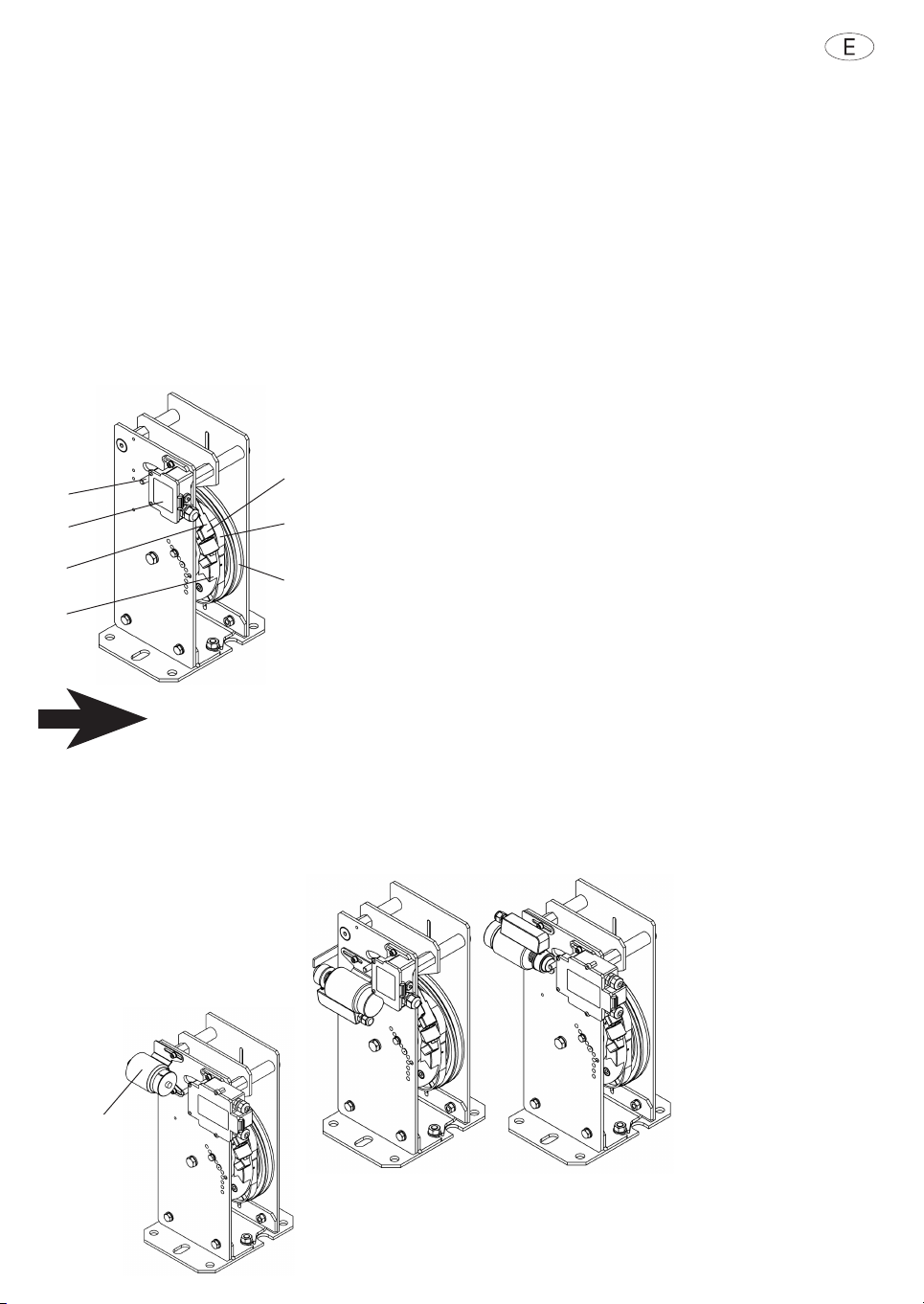
Lo stesso limitatore di elocità (Fig. 1) è costituito da una puleggia con:
• Ruota del limitatore (1) con gola trapezoidale con scarico, per alloggiare la fune del limitatore;
• Gola di pro a per test di funzionamento;
• Corona a camme (2);
• Eccentrico di arresto (3).
La fune, bloccata sulla tiranteria di innesto del paracadute e tenuta tesa da un peso, aziona la ruota del
limitatore (1) tramite la pressione della fune nella gola trapezoidale con scarico.
Oltre alla gola trapezoidale, iene inoltre montata, sulla ruota del limitatore,
una corona a camma (2) con eccentrico di arresto (3). Detta corona fa
funzionare il pendolo (4) per mezzo di una carrucola montata su di un
cuscinetto a sfera, con moto oscillatorio erso l’alto e erso il basso.
Il pendolo iene tirato alla corona a camme tramite una molla di trazione
precaricata, corrispondente alla elocità di inter ento pre ista.
Con il raggiungimento della elocità di inter ento, l’ampiezza del pendolo
di enta così grande, che l’innesto a denti frontali oscillante (5) incontra la
guida periferica dell’eccentrico di arresto e i iene bloccata da una camma.
Un perno d’acciaio (6) applicato sul pendolo aziona, prima del bloccaggio
meccanico del pendolo, l’interruttore di sicurezza (7). In tal modo, si
interrompe la corrente di comando dell’impianto.
I limitatori di elocità possono anche essere forniti con comando a distanza.
In caso di montaggio nel pozzo dell’ascensore, il limitatore di elocità de e essere dotato di
comando a distanza, oppure de e essere facilmente accessibile dall’esterno
(ad es. tramite una porticina di manutenzione).
Per mezzo di un tasto, il comando a distanza (fig.2, pos.8) pro oca l’innesto del pendolo su percorso
elettromagnetico nella scatola dell’interruttore stesso.
I limitatori di elocità dotati di comando a distanza facilitano i controlli di funzionamento.
I limitatori di elocità possiedono l’omologazione in conformità alla Diretti a per ascensori 2014/33/UE, con i
seguenti numeri della pro a di omologazione EU:
• LK 120 : TÜV EU-OG 280
• LX 150 : TÜV EU-OG 295/1
• LX 180 : TÜV EU-OG 296
• LK 200 : TÜV EU-OG 182
• LK 250 : TÜV EU-OG 183
• LK 300 : TÜV EU-OG 184
• LK 315 : TÜV EU-OG 186
5
6
7
4
3
5
2
1
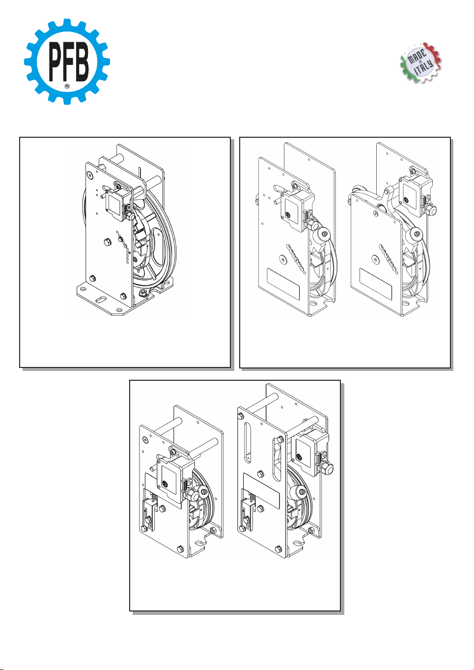
Fig. 1
In caso di utilizzo su
nuo i impianti in
conformità a quanto
richiesto dalla normati a
Europea per il mo imento
incontrollato di cabina, il
limitatore può essere
fornito completo di un
dispositi o elettro-
magnete in combinazione
con il relati o
alimentatore o senza; per
il funzionamento e
l’utilizzo dei dispositi i di
cui sopra si de e fare
riferimento allo specifico
libretto d’uso e
manutenzione fornito
separatamente.
Fig. 2
Limitatore
di elocità
con
comando a
distanza
Fig. 3
Limitatore di elocità
con dispositi o per
mo imento incontrollato
di cabina
Fig. 3