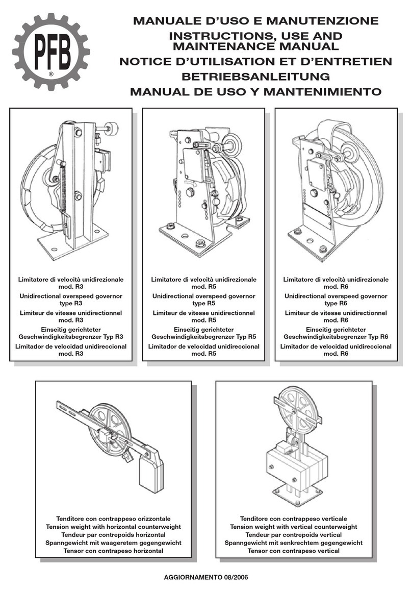
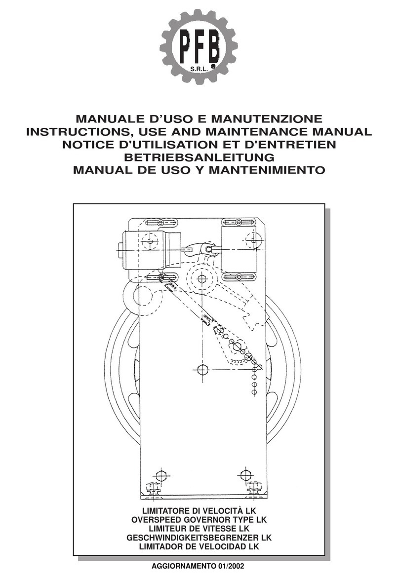
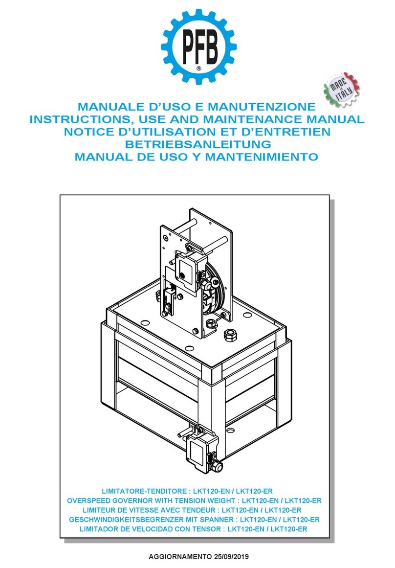
PFB LKT120 Specification sheet

MANUALE D’USO E MANUTENZIONE
INSTRUCTIONS, USE AND MAINTENANCE MANUAL
NOTICE D’UTILISATION ET D’ENTRETIEN
BETRIEBSANLEITUNG
MANUAL DE USO Y MANTENIMIENTO
AGGIORNAMENTO 16/11/2021
LIMITATORE-TENDITORE : LKT120
OVERSPEED GOVERNOR WIT TENSION WEIG T : LKT120
LIMITEUR DE VITESSE AVEC TENDEUR : LKT120
GESC WINDIGKEITSBEGRENZER MIT SPANNER : LKT120
LIMITADOR DE VELOCIDAD CON TENSOR : LKT120

2
ISTRUZIONI PER L’USO
INDICE PAGINA
1 INFORMAZIONI PRIMA DELL’INIZIO DEL MONTAGGIO 5
1.1.2 Descrizione, modo di funzionamento 8
1.2 Responsabilità e garanzia 14
1.3 Misure precauzionali di sicurezza 14
1.4 struzioni di lavoro sugli elementi strutturali di sicurezza 19
1.5 Preparazione del lavoro 21
1.6 Targhetta del prodotto, contrassegno, identificazione 23
1.7 Fornitura complessiva 24
2 MONTAGGIO 25
2.1 Montaggio del Limitatore-Tenditore 25
2.1.1 Montaggio nel pozzo ascensore - preparazione 25
2.2 Montaggio della fune del limitatore/tenditore con contrappeso 30
2.3 nstallazione elettrica degli interruttori di sicurezza 35
3 OPERAZIONI DI MESSA A PUNTO 38
3.1 Limitatore di velocità 38
3.2 Tenditore con contrappeso 38
4 PROVA DI FUNZIONAMENTO 42
5 MANUTENZIONE, CONTROLLO E RIPARAZIONE 47
5.1 Manutenzione e controllo 47
5.2 Esecuzione delle riparazioni 47
6 DATI TECNICI 52
6.1 Limitatore-Tenditore LKT120 52
OPERATING INSTRUCTIONS
INDEX PAGE
1 INFORMATION BEFORE BEGINNING T E ASSEMBLY 5
1.1.2 Description, operation mode 9
1.2 Responsibility and guarantee 15
1.3 Safety precautions 15
1.4 Working instructions on safety structural elements 19
1.5 Pre-Operations 21
1.6 Type-plate, Test mark, identification 23
1.7 Constitution of supply 24
2 ASSEMBLY 26
2.1 Assembly of the Governor-Tensioner 26
2.1.1 Assembly in the elevator shaft - preparation 26
2.2 Assembly of the rope of the overspeed governor/tension weight with counterweight 31
2.3 Electric installation of the safety switches 35
3 SETTING UP OPERATIONS 38
3.1 Overspeed governor 38
3.2 Tension weight with counterweight 38
1.1.1 Descrizione generale 7
1.1.1 General description 7
6.2 Opzionale: Limitatore-Tenditore con fissaggio alla guida 53

3
4 OPERATION TESTING 43
5 MAINTENANCE, CONTROL AND REPAIR 48
5.1 Maintenance and control 48
5.2 Execution of repairs 48
6 TEC NICAL DATA 52
6.1 Overspeed governor with Tension weight LKT120 52
INSTRUCTIONS D’UTILISATION
SOMMAIRE PAGE
1 INFORMATIONS AVANT DE COMMENCER LE MONTAGE 5
1.1.2 Description, mode de fonctionnement 10
1.2 Responsabilité et garantie 16
1.3 Mesures de précaution concernant la sécurité 16
1.4 nstructions de travail concernant les éléments structuraux de sécurité 20
1.5 Préparation du travail 22
1.6 Plaquette du produit, marque, identification 23
1.7 Fourniture d’ensemble 24
2 MONTAGE 27
2.1 Montage du Limiteur-Tendeur 27
2.1.1 Montage dans la cage d’ascenseur - préparation 27
2.2 Montage du câble du limiteur/tendeur avec contrepoids 32
2.3 nstallation électrique des interrupteurs de sécurité 36
3 OPÉRATIONS DE MISE AU POINT 39
3.1 Limiteur de vitesse 39
3.2 Tendeur par contrepoids 39
4 ESSAI DE FONCTIONNEMENT 44
5 ENTRETIEN, CONTRÔLE, RÉPARATION 49
5.1 Entretien et contrôle 49
5.2 Exécution des réparations 49
6 DONNÉES TEC NIQUES 52
6.1 Limiteur de vitesse avec Tendeur LKT120 52
BETRIEBSANLEITUNG
IN ALTSVERZEIC NIS SEITE
1 INFORMATIONEN VOR BEGINN DER MONTAGE 6
1.1.2 Beschreibung, Funktionsweise 11
1.2 Haftung und Gewährleistung 17
1.3 Sicherheitsvorkehrungen 17
1.4 Hinweise zur Arbeit an Sicherheitsbauteilen 20
1.5 Arbeitsvorbereitung 22
1.6 Typenschild, Kennzeichnung, dentifizierung 23
1.7 Lieferumfang
24
1.1.1 Description générale 7
1.1.1 Allgemeine Beschreibung 7
6.2 Optional: Overspeed governor with Tension weight with guide rail mounting. 53
6.2 Optionnel : Limiteur/Tendeur avec fixation a la guide. 53

4
2 MONTAGE 28
2.1 Montage des Begrenzer-Spanner 28
2.1.1 Montage im Aufzugsschacht - Vorbereitung 28
2.2 Montage des Begrenzerseils/Spanngewichts 33
2.3 Elektrische nstallation der Sicherheitsschalter 36
3 EINSTELLARBEITEN 39
3.1 Geschwindigkeitsbegrenzer 39
3.2 Spanngewicht 39
4 FUNKTIONSPRÜFUNG 45
5 WARTUNG, KONTROLLE UND REPARATUR 50
5.1 Wartung und Kontrolle 50
5.2 Ausführung von Reparaturen 50
6 TEC NISC E DATEN 52
6.1 Geschwindigkeitsbegrenzer mit Spanner LKT120 52
INSTRUCCIONES DE MONTAJE Y USO
ÍNDICE PÁGINA
1 INFORMACIÓN PREVIAS AL MONTAJE 6
1.1.2 Descripción y modo de funcionamiento 12
1.2 Responsabilidad y garantía 18
1.3 Medidas preventivas de seguridad 18
1.4 nstrucciones de trabajo sobre los elementos estructurales de seguridad 21
1.5 Operaciones previas a la instalación 22
1.6 Placa de datos del producto, marca e identificación 23
1.7 Equipamientos 24
2 MONTAJE 29
2.1 Montaje del Limitadores-Tensores 29
2.1.1 Montaje en el hueco del ascensor - preparación 29
2.2 Montaje del cable del limitador/tensor con contrapeso 34
2.3 nstalación eléctrica de los interruptores de seguridad 37
3 OPERACIONES DE PUESTA A PUNTO 40
3.1 Limitador de velocidad 40
3.2 Tensor con contrapeso 40
4 PRUEBA DE FUNCIONAMIENTO 46
5 MANTENIMIENTO, COMPROBACIÓN Y REPARACIÓN 51
5.1 Mantenimiento y comprobación 51
5.2 Reparaciones 51
6 DATOS TÉCNICOS 52
6.1 Limitador de velocidad con Tensor LKT120 52
1.1.1 Descripción general 7
6.2 Optional: Einrichtung mit Befestigung an den Führungsschienen. 53
6.2 Opcional: Limitador de velocidad con Tensor con montaje a la guía. 53

1 INFORMAZIONI GENERALI PRIMA DELL’INIZIO DEL MONTAGGIO
1 GENERAL INFORMATION BEFORE BEGINNING T E ASSEMBLY
1 INFORMATION GÉNÉRALES AVANT DE COMMENCER LE MONTAGE
●l limitatore di velocità deve essere montato solo in posizione verticale con fissaggio a
pavimento o appeso e con angolo di avvolgimento della fune di 180° sulla puleggia.
●l limitatore di velocità non può essere installato all’aperto, poiché esposto ad intemperie ed
agenti atmosferici.
●l limitatore di velocità non può essere montato capovolto.
●l limitatore di velocità non può essere montato inclinato.
●Temperatura d’esercizio consentita -20°C / +80°C.
●l limitatore di velocità viene fornito nella versione base senza alcun accessorio; in fase di
ordine occorre precisare ogni accessorio richiesto (carter, antiscarrucolamento, comando a
distanza, ecc) .
●The overspeed governor must always be in vertical position (pit mounted or hang up) and the
rope must have at least 180° angle of wrap.
●The overspeed governor cannot be mounted outdoors, as it has not to be exposed to weather
and atmospheric agents.
●The overspeed governor cannot be mounted upside down.
●The overspeed governor cannot be mounted inclined.
●Permissible operating temperature -20°C / +80°C .
●The overspeed governor is supplied in the basic version without any accessories.
●When ordering, it is necessary to specify each accessory required (protection cover, rope
safety guard, remote control, etc.).
●Le limiteur de vitesse doit être monté uniquement en position verticale avec fixation au sol ou
suspendue et avec un angle d'enroulement de 180° du câble sur la poulie.
●Le limiteur de vitesse ne peut pas être installé à l'extérieur, car il est exposé aux intempéries
et aux agents atmosphériques.
●Le limiteur de vitesse ne peut pas être monté à l'envers.
●Le limiteur de vitesse ne peut pas être monté de biais.
●Température de fonctionnement autorisée -20°C / +80°C.
●Le limiteur de vitesse est fourni dans la version de base sans aucun accessoire ; lors de la
commande, il est nécessaire de préciser chaque accessoire souhaité (capotage, anti-
dégorgement, commande à distance, etc.)
5

1 ALLGEMEINES VOR MONTAGEBEGINN
1 GENERALIDADES PREVIAS AL MONTAJE
●Der Geschwindigkeitsbegrenzer darf nur in senkrechter Position mit Boden- oder
Hängebefestigung und mit einem Umschlingungswinkel des Seils auf der Umlenkrolle von
180° montiert werden.
●Der Geschwindigkeitsbegrenzer soll nicht im Freien installiert werden, da er schlechtem
Wetter und Witterungseinflüssen ausgesetzt ist.
●Der Geschwindigkeitsbegrenzer kann nicht verkehrt herum montiert werden.
●Der Geschwindigkeitsbegrenzer kann nicht schräg montiert werden.
●Zulässige Betriebstemperatur -20 ° C / + 80 ° C.
●Der Geschwindigkeitsbegrenzer wird in der Basisversions ohne Zubehör geliefert; bei der
Bestellung muss jedes benötigte Zubehör (Abdeckung, Seilsprungsicherung, Fernauslösung
usw.) angegeben werden.
●El limitador de velocidad solo debe montarse en posición vertical con fijación al suelo o
colgante y con un ángulo de enrollado del cable de 180 ° sobre la polea.
●El limitador de velocidad no se puede instalar en exteriores, ya que está expuesto a las
inclemencias del tiempo y agentes atmosféricos.
●El limitador de velocidad no se puede montar al revés.
●El limitador de velocidad no se puede montar sobre un plano inclinado.
●Temperatura de funcionamiento permitida -20 ° C / + 80 ° C.
●El limitador de velocidad se suministra en la versión básica sin accesorios; al momento del
pedido, es necesario especificar cada accesorio requerido (capota de protección, anti-salida
de cable, mando a distancia, etc.)
6

1.1.1 DESCRIZIONE GENERALE
1.1.1 GENERAL DESCRIPTION
1.1.1 DESCRIPTION GÉNÉRALE
1.1.1 ALLGEMEINE BESC REIBUNG
1.1.1 DESCRIPCIÓN GENERAL
Limitatori-Tenditori LKT120 combinano in un unico dispositivo di sicurezza le funzionalità dei limitatori di
velocità LK120 e quelle dei tenditori con contrappeso verticale R4V e sono predisposti per essere montati sul
fondo del pozzo vano ascensore. Come “optional” è disponibile su ordinazione una staffa per il montaggio alla
guida.
The LKT120 Governor-Tensioner combine in a single safety device the functions of the LK120 overspeed
governor and those of the R4V vertical counterweight tensioners and are designed to be mounted on the
bottom of the elevator shaft. A plate for mounting on the rail is available on request as an “option”.
Le Limiteur-Tendeur LKT120 combinent en un seul dispositif de sécurité les fonctions des limiteurs de vitesse
LK120 et celles des tensionneurs de contrepoids vertical R4V et sont conçus pour être montés sur le fond de la
gaine d'ascenseur. En «option», une plaque de montage a la guide est disponible sur commande.
Die LKT120 Begrenzer-Spanner kombinieren die Funktionen der Geschwindigkeitsbegrenzer LK120 mit denen
von Spanngewichte mit vertikalem Gegengewicht R4V und sind so ausgelegt, dass Sie am Boden des
aufzugsschachtraumes angebracht werden können. Optional ist eine Platte zur Montage an der Schiene auf
Bestellung erhältlich.
Los Limitadores-Tensores LKT120 combinan en un solo dispositivo de seguridad las funciones de los
limitadores de velocidad LK120 y las de los tensores de contrapeso vertical R4V y están diseñados para ser
montados en la parte inferior del pozo del elevador. Como "opción", se puede solicitar una placa para el
montaje a la guía.
7
Limitatore di velocità
Overspeed governor
Limiteur de vitesse
Geschwindigkeitsbegrenzer
Limitador de velocidad
Tenditore con contrappeso verticale
Tension weight with vertical counterweight
Tendeur avec contrepoids vertical
Spanner mit vertikalem Gegengewicht
Tensor con contrapeso vertical

6
7
4
3
5
2
1
8
1.1.2 DESCRIZIONE, MODO DI FUNZIONAMENTO
l limitatore di velocità è un dispositivo di sicurezza che viene messo in funzione in caso di superamento della
velocità ammessa della cabina dell’ascensore.
Nel caso in cui la cabina dell’ascensore, durante la corsa in salita o in discesa, superi la sua velocità nominale
ammessa fino al raggiungimento della velocità di intervento, il limitatore di velocità si innesta e fa scattare,
sulla fune del limitatore, un dispositivo frenante, più precisamente il paracadute, che è posizionato sulla
cabina dell’ascensore. La cabina si arresta e viene trattenuta dalle guide.
Lo stesso limitatore di velocità (Fig. 1) è costituito da una puleggia con:
• Ruota del limitatore (1) con gola trapezoidale con scarico, per alloggiare la fune del limitatore;
• Gola di prova per test di funzionamento;
• Corona a camme (2);
• Eccentrico di arresto (3).
La fune, bloccata sulla tiranteria di innesto del paracadute e tenuta tesa da un peso, aziona la ruota del
limitatore (1) tramite la pressione della fune nella gola trapezoidale con scarico.
Oltre alla gola trapezoidale, viene inoltre montata, sulla ruota del limitatore,
una corona a camma (2) con eccentrico di arresto (3). Detta corona fa
funzionare il pendolo (4) per mezzo di una carrucola montata su di un
cuscinetto a sfera, con moto oscillatorio verso l’alto e verso il basso.
l pendolo viene tirato alla corona a camme tramite una molla di trazione
precaricata, corrispondente alla velocità di intervento prevista.
Con il raggiungimento della velocità di intervento, l’ampiezza del pendolo
diventa così grande, che l’innesto a denti frontali oscillante (5) incontra la
guida periferica dell’eccentrico di arresto e vi viene bloccata da una camma.
Un perno d’acciaio (6) applicato sul pendolo aziona, prima del bloccaggio
meccanico del pendolo, l’interruttore di sicurezza (7). n tal modo, si
interrompe la corrente di comando dell’impianto.
n conseguenza al suo montaggio nel pozzo dell’ascensore, il limitatore di velocità deve
essere dotato di comando a distanza, oppure deve essere facilmente accessibile
dall’esterno (ad es. tramite una porticina di manutenzione).
Per mezzo di un tasto, il comando a distanza (fig.2, pos.8) provoca l’innesto del pendolo su percorso
elettromagnetico nella scatola dell’interruttore stesso.
limitatori di velocità dotati di comando a distanza facilitano i controlli di funzionamento.
limitatori di velocità possiedono l’omologazione in conformità alla Direttiva per ascensori 2014/33/UE, con i
seguenti numeri della prova di omologazione EU:
• LK 120 : TÜV EU-OG 280
Fig. 1
n caso di utilizzo su
nuovi impianti in
conformità a quanto
richiesto dalla normativa
Europea per il movimento
incontrollato di cabina, il
limitatore può essere
fornito completo di un
dispositivo elettro-
magnete in combinazione
con il relativo
alimentatore o senza; per
il funzionamento e
l’utilizzo dei dispositivi di
cui sopra si deve fare
riferimento allo specifico
libretto d’uso e
manutenzione fornito
separatamente.
Fig. 2
Limitatore
di velocità
con
comando a
distanza
Fig. 3
Limitatore di velocità
con dispositivo per
movimento incontrollato
di cabina
Fig. 3
8

6
7
4
3
5
2
1
8
1.1.2 DESCRIPTION, OPERATION MODE
The overspeed governor is a safety device which turns on when the allowed speed of the elevator car is
exceeded.
f the elevator car, during its upward/downward run, exceeds its nominal permissible speed, until the tripping
speed is reached, the overspeed governor turns on and, in turn, releases – on the overspeed governor rope – a
brake mechanism, more precisely the safety gear on the elevator car. The elevator car stops and is kept back
by the guides.
The same overspeed governor (fig. 1) is made up of pulley with:
• governor wheel (1) with trapezoidal undercut groove, to house the overspeed governor rope;
• test grooves for operation tests;
• cam rim (2);
• eccentric stop (3).
The rope, secured to the clamp of the safety gear and stretched by a weight, operates the governor wheel (1)
through the pressure of the rope in the trapezoidal undercut groove.
Beside the trapezoidal groove, a cam rim (2) with eccentric stop (3) is also mounted on the governor wheel.
Such rim allows the pendulum (4) to operate with an upward/downward
oscillating motion, by means of a pulley mounted on a ball bearing.
The pendulum is drawn to the cam rim by a preloaded tension spring,
corresponding to the scheduled tripping speed.
By reaching the tripping speed, the swing of the pendulum becomes so
extended, that the oscillating dog clutch (5) meets the peripheral guide of
the eccentric stop, where it is clamped by a cam.
A steel pin (6) applied on the pendulum operates the safety switch (7)
before the mechanical clamping of the pendulum. Through it, the control
power of the plant is switched off.
As a result of its assembly in the elevator shaft, the overspeed governor must be supplied
with remote control or it must be easily accessible from the outside.
(e.g. through a maintenance door).
By means of a key, the remote control (fig.2, pos.8) causes the insertion of the pendulum on the
electromagnetic way in the safety switch box.
Overspeed governors fitted with remote control make the operation controls easy.
Overspeed governors are provided with the homologation according to the rules and regulations for elevators
2014/33/EU, with the following EU-type-approval test numbers:
• LK 120 : TÜV EU-OG 280
Fig. 1
On the use in new
facilities in accordance
with the requirements of
European standard for
the uncontrolled
movement of the cab, the
overspeed governor can
be supplied complete
with a solenoid device in
combination with its
feeder or without; for the
operation and the use of
the above devices please
refer to the specific
maintenance manual
provided separately.
Fig. 3
Overspeed governor
with uncontrolled car
movement device
Fig. 2
Overspeed
governor
with remote
control
9

6
7
4
3
5
2
1
8
1.1.2 DESCRIPTION, MODE DE FONCTIONNEMENT
Le limiteur de vitesse est un dispositif de sécurité qui est mis en fonction en cas de dépassement de la vitesse
autorisée dans la cabine de l’ascenseur.
Au cas où la cabine de l’ascenseur, au cours de la course de montée ou de descente, dépasserait sa vitesse
nominale autorisée (jusqu’à atteindre la vitesse d’intervention), le limiteur se connecte et fait déclencher, sur
le câble du limiteur, un dispositif de freinage nommé parachute, qui est positionné sur la cabine de
l’ascenseur. La cabine s’arrête et est retenue par les glissières.
Le limiteur de vitesse (Fig. 1) se compose d’une poulie dotée de:
• roue du limiteur (1) avec gorge trapézoïdale dotée de déchargement pour loger le câble du limiteur;
• gorge d’essai pour test de fonctionnement;
• couronne à cames (2);
• excentrique d’arrêt (3).
Le câble, bloqué sur les tirants d’embrayage du parachute et tendu par un poids, actionne la roue du limiteur
(1) par sa pression sur la gorge trapézoïdale dotée de sortie d’évacuation.
Outre la gorge trapézoïdale, une couronne à cames (2) avec excentrique
d’arrêt (3) est aussi montée sur la roue du limiteur. Cette couronne fait
fonctionner le pendule (4) par l’intermédiaire d’une poulie montée sur un
roulement à billes (avec mouvement oscillatoire vers le haut et vers le bas).
Le pendule est tiré vers la couronne à cames par un ressort de traction
préchargé, qui correspond à la vitesse d’intervention prévue.
Une fois la vitesse d’intervention atteinte, l’ampleur du pendule devient
tellement grande que l’accouplement à crabots frontaux oscillant (5)
rencontre la glissière périphérique de l’excentrique d’arrêt et est bloquée
dans cette position par une came.
Un pivot en acier (6) appliqué sur le pendule actionne l’interrupteur de
sécurité (7) avant le blocage mécanique du pendule. De cette façon, le
courant de commande de l’installation est coupé.
En raison de son montage dans la cage d'ascenseur, le limiteur de vitesse doit être doté de
commande à distance ou bien il doit être aisément accessible de l’extérieur.
(par ex.: par une petite trappe d’entretien).
Par la pression d’une touche, la commande à distance (Fig.2, Pos.8) produit l’enclenchement du pendule sur le
parcours électromagnétique dans le carter de l’interrupteur même.
Les limiteurs de vitesse dotés de commande à distance rendent les contrôles de fonctionnement plus faciles.
Les limiteurs de vitesse sont pourvu de l’homologation en conformité avec la Directive 2014/33/UE en matière
d’ascenseurs, portant les numéros d’essai d’homologation EU suivants:
• LK 120 : TÜV EU-OG 280
Fig. 1
Fig. 2
Limiteur de
vitesse
avec
commande
à distance
En cas d’utilisation sur
nouvelles installations en
conformité avec les
exigences de la norme
européenne pour les
mouvements incontrôlés
de la cabine, le limiteur
peut être livré avec un
dispositif électro en
combinaison avec son
dispositif d’alimentation ou
sans, pour le
fonctionnement et
l’utilisation des dispositifs
ci-dessus s’il vous plaît se
référer au manuel
d’entretien spécifique,
fourni séparément.
Fig. 3
Limiteur de vitesse
avec dispositif pour
mouvement
incontrôlé de la
cabine
10

6
7
4
3
5
2
1
8
1.1.2 BESC REIBUNG, FUNKTIONSWEISE
Der Geschwindigkeitsbegrenzer ist eine Sicherheitseinrichtung, die bei Überschreiten der zulässigen
Fahrkorbgeschwindigkeit zum Einsatz kommt.
Überschreitet der Fahrkorb während der Auf-oder Abwärtsfahrt seine zulässige Nenngeschwindigkeit bis zum
Erreichen der Auslösegeschwindigkeit, dann rückt der Geschwindigkeitsbegrenzer ein und löst über das
Begrenzerseil eine eventuell vorhandene aufwärtswirkende Bremseinrichtung bzw. die Fangvorrichtung am
Fahrkorb aus. Der Fahrkorb wird zum Stillstand gebracht und an den Führungsschienen festgehalten.
Der Geschwindigkeitsbegrenzer (Abb. 1) selbst besteht aus einer Begrenzerscheibe mit:
• Reglerrad (1) mit unterschnittener Keilrille zur Aufnahme des Begrenzerseils;
• Prüfrille für Testläufe;
• Kurvenkranz (2);
• Sperrnocken (3).
Das am Einrückgestänge der Fangvorrichtung befestigte und durch ein Gewicht gespannte Seil treibt das
Reglerrad (1) über die Seilpressung in der unterschnittenen Keilrille an.
Neber der Keilrille ist am Reglerrad außerdem ein Kurvenkranz (2) mit Sperrnocken (3) angebracht.
Dieser Kurvenkranz bringt das Fangpendel (4) über eine kugelgelagerte
Rolle in aufund abschwingende Bewegung.
Das Fangpendel wird über eine, entsprechend der vorgesehenen
Auslösegeschwindigkeit, vorgespannte Zugfeder an den Kurvenkranz
gezogen.
Beim Erreichen der Auslösegeschwindigkeit wird der Ausschlang des
Pendels so groß, daß die Pendelklaue (5) in die Umfangsbahn der
Sperrnocken gerät und dort von einer Nocke festgeklemmt wird.
Ein am Fangpendel angebrachter Stahlbolzen (6) betätigt vor der
mechanischen Klemmung des Pendels den Sicherheitsschalter (7). Dadurch
wird der Steuerstrom der Anlage unterbrochen.
Aufgrund seiner Montage im Aufzugsschacht muss der Geschwindigkeitsbegrenzer mit
Fernauslösung ausgerüstet oder von außen leicht zugänglich sein.
(z.B. durch eine Wartungstür).
Die Fernauslösung (Abb.2, Pos.8) bewirkt per Taster das Einrücken des Fangpendels auf
elektromagnetischem Weg im Gehäuse des Sicherheitsschalters.
Geschwindigkeitsbegrenzer mit Fernauslösung erleichtem Funktionsprufüngen.
Die Geschwindigkeitsbegrenzer besitzen die Zulassung nach AufzR 2014/33/EU mit folgendem EU-
Baumusterprüfungsnummern:
• LK 120 : TÜV EU-OG 280
Abb. 1
Bei Einsatz in neuen
Anlagen in
Übereinstimmung mit den
Anforderungen der
europäischen Norm für die
unkontrollierte Bewegung
der Kabine kann der
Begrenzer komplett mit
einer Magnetspule in
Kombination mit seiner
Stromversorger oder ohne
geliefert werden, für die
Bedienung und die
Verwendung der oben
genannten Geräte
beziehen Sie sich auf die
spezifische
Wartungsanleitung, die
separat zur Verfügung
gestellt werden.
Abb. 3
Geschwindigkeitsbegrenzer
mit Vorrichtung für
unkontrollierte Bewegungen
der Kabine - A3
Abb. 2
Geschwindigkeitsbegrenzer mit Fernauslösung 11

6
7
4
3
5
2
1
8
1.1.2 DESCRIPCIÓN Y MODO DE FUNCIONAMIENTO
El limitador de velocidad es un dispositivo de seguridad que se pone en funcionamiento si la cabina del
ascensor supera el límite de velocidad permitido.
Si, durante el desplazamiento en sentido ascendente o descendente, la cabina del ascensor supera la
velocidad nominal permitida y alcanza la velocidad de intervención, el limitador de velocidad se activará y
accionará un dispositivo de freno en el cable del limitador, concretamente el paracaídas situado en la cabina
del ascensor. La cabina se bloqueará automáticamente sobre sus guías.
El limitador de velocidad (fig. 1) está formado por una polea con:
• rueda del limitador (1) con acanaladura trapezoidal con descarga, para alojar el cable del limitador;
• acanaladura de prueba para comprobar el funcionamiento;
• corona de levas (2);
• excéntrica de bloqueo (3).
El cable, sujeto al varillaje de accionamiento del paracaídas y tensado por un contrapeso, acciona la rueda del
limitador (1) mediante la presión que ejerce en la acanaladura trapezoidal con descarga.
En la rueda del limitador, además de la acanaladura trapezoidal, se
encuentra una corona de levas (2) con una excéntrica de bloqueo (3). Esta
corona acciona el péndulo (4) mediante una polea montada en un cojinete
de bolas, con un movimiento de oscilación de arriba a abajo.
El péndulo es empujado hacia la corona de levas mediante un muelle de
tracción precargado en función de la velocidad de intervención prevista.
Al alcanzar dicha velocidad de intervención, el campo de oscilación del
péndulo aumenta de tal manera que el acoplamiento oscilante de dientes
delanteros rectos (5) entra en contacto con la guía periférica de la
excéntrica de bloqueo y una leva la bloquea.
Antes del bloqueo mecánico del péndulo, una perno de acero (6) que tiene
montado acciona el interruptor de seguridad (7). De esta manera
desconecta la corriente de la instalación.
Como resultado de su montaje en el hueco del ascensor, es necesario que el limitador de
velocidad esté dotado de mando a distancia, o bien esté situado ed un lugar fácilmente
accesible desde el exterior (p. ej. mediante una pequeña puerta de servicio).
Mediante un pulsador, el mando a distancia (fig.2, pos.8) conecta el péndulo al circuito electromagnético de la
caja del proprio interruptor.
Los limitadores de velocidad equipados con mando a distancia facilitan el control del funcionamiento.
Los limitadores de velocidad están homologados de acuerdo con la Directiva para ascensores 2014/33/UE,
con los siguientes números de homologación EU:
• LK 120 : TÜV EU-OG 280
Fig. 1
Fig. 2
Limitador
de
velocidad
con mando
a distancia
En cuanto al uso en
nuevas instalaciones de
acuerdo con los requisitos
de la norma europea para
el movimiento
incontrolado de la cabina,
el limitador puede ser
suministrado completo
con un dispositivo de
solenoide en combinación
con su alimentador o sin
para la operación y el uso
de los dispositivos
anteriores, por favor
consulte el manual de
mantenimiento específico,
suministrado por
separado.
Fig. 3
Limitador de velocidad
con dispositivo para
movimiento incontrolado
de la cabina - A3
12

Per il montaggio nel fondo del vano di corsa, il limitatore di velocità può essere dotato di comando a
distanza.
DISPOSIZIONE SUL FONDO DEL VANO DI CORSA
For the assembly on the bottom of the elevator shaft, the overspeed governor can be supplied with
remote control.
DISPOSITION ON T E BOTTOM OF T E ELEVATOR S AFT
Pour le montage dans le bas du compartiment de course, le limiteur de vitesse peut être doté de
commande à distance.
ARRANGEMENT DANS LE FONDS DU COMPARTIMENT DE COURSE
Für die Montage im unteren dem Brunnen ist der Geschwindigkeitsbegrenzer mit einer Fernauslösung
ausrüstbar.
ANORDNUNG IM UNTEREN DEM BRUNNEN
Para el montaje en la parte inferior del hueco de carrera, el limitador puede equiparse con mando a
distancia.
DISPOSICIÓN EN EL FONDO DEL UECO DE CARRERA
13
Capofune
Rope anchor
Cosse
Seilschloß
Extremo del cable
Fune del limitatore
Governor rope
Câble du limiteur
Begrenzerseil
Cable del limitador
Porticina di manutenzione
Maintenance door
Trappe d’entretien
Wartungstür
Puerta de servicio
Paracaduti
Safety gears
Parachutes
Fangvorrichtungen
Paracaídas
Organo di comando
Control device
Organe de commande
Schaltkulisse
Mando
Limitatore-Tenditore
Overspeed governor with Tension weight
Limiteur de vitesse avec Tendeur
Geschwindigkeitsbegrenzer mit Spanner
Limitador de velocidad con Tensor

14
1.2 RESPONSABILITÀ E GARANZIA
Queste istruzioni per l’uso sono destinate a coloro che sono esperti di montaggio e manutenzione degli
ascensori. Presupposti fondamentali sono le conoscenze esaurienti sulla costruzione degli stessi.
La ditta P.F.B. declina qualsiasi responsabilità per danni derivati da azionamenti che non sono stati eseguiti a
regola d’arte o simili, in conformità alle seguenti istruzioni per l’uso e che quindi danneggiano le caratteristiche
del prodotto.
L’obbligo di garanzia della ditta P.F.B. può decadere, se l’elemento strutturale viene impiegato in maniera
diversa da quella descritta nelle seguenti istruzioni.
Per motivi di sicurezza tecnica, generalmente non è ammesso:
• Montare limitatori di velocità contraffatti o destinati ad altri scopi che quello inteso.
• Effettuare modifiche di qualsiasi tipo sul limitatore di velocità.
1.3 MISURE PRECAUZIONALI DI SICUREZZA
n linea di principio, i montatori stessi sono responsabili per la sicurezza del lavoro.
L’osservanza ed il rispetto di tutte le norme si sicurezza in vigore e delle direttive di legge costituisce la
premessa per evitare danni a persone ed al prodotto durante i lavori di montaggio, manutenzione e
riparazione.
Le istruzioni che devono essere rispettate in modo particolare in tema di sicurezza e prevenzione dei sinistri
sono messe in evidenza nei seguenti simboli:
Segnale di pericolo generico
Segnalazione di maggior pericolo di lesioni (es.: spigoli schiacciati)
Segnalazione di pericolo di danneggiamento dell’elemento strutturale
(es: in seguito ad errori di montaggio)
Segnalazione di informazioni importanti
Le seguenti istruzioni per l’uso sono parte costitutiva di tutto l’impianto. Devono essere conservate in un luogo
protetto e sempre accessibili (come ad es. in sala macchine).

15
1.2 RESPONSIBILITY AND GUARANTEE
These operating instructions are addressed to persons, who are well acquainted with the assembly of
elevators. Thorough knowledge of the elevator construction and maintenance is necessary.
The firm P.F.B. takes no responsibility for damages, deriving from operations or actions, that have not been
carried out properly according to the following operating instructions and that therefore may damage the
characteristics of the product.
P.F.B.’s guarantee may not be valid if the component part is used in a different way other than that described
in these instructions.
For technical security reasons, it is generally not allowed:
●assembling of wrong overspeed governors, or governors destined to other applications other than the
intended one.
• introduction of changes of any ind to the overspeed governor.
1.3 SAFETY PRECAUTIONS
Generally the fitters are themselves responsible for the safety of the work.
The observance and respect of all the safety regulations in force and the legal rules are necessary to avoid
damages to persons and to the product during the assembly, maintenance and repair.
nstructions that should be particularly considered regarding safety and damage prevention are pointed out
with the following symbols:
General indication of danger
ndication of higher danger of injuries (e.g.: squashed edges. etc.)
ndication of danger of possible damages to the structural element and to its component parts
(e.g. mistakes in the assembly, etc.)
ndication of important information
The following operating instructions are an essential part of the whole system. They must be kept in a
protected and always accessible place (e.g. the engine room).

16
1.2 RESPONSABILITÉS ET GARANTIE
Ces instructions d’utilisation sont destinées à tous ceux qui sont spécialisés dans le montage et l’entretien des
ascenseurs. Dans ce but, des connaissances exhaustives en matière de construction des ascenseurs
constituent des conditions nécessaires.
La maison P.F.B. décline toute responsabilité pour les dommages dérivant d’actionnements non effectués
selon les règles de l’art ou à problèmes similaires causés par des opérations qui n’ont pas été exécutés en
conformité avec les instructions d’utilisation mentionnées ci-après et qui, par conséquent, peuvent nuire aux
caractéristiques du produit.
L’obligation de la maison P.F.B. à fournir une garantie peut être invalidée si l’élément structurel est utilisé de
façon différente que celle indiquée dans les instructions suivantes.
Pour des raisons de sécurité technique, en principe, les opérations suivantes ne sont pas autorisées:
• monter des limiteurs de vitesse contrefaits ou destinés à d’autres buts que celui qui est prévu;
• effectuer des modifications de tout type sur le limiteur de vitesse.
1.3 MESURES DE PRÉCAUTION CONCERNANT LA SÉCURITÉ
En principe, ce sont les monteurs qui sont responsables de la sécurité du travail.
L’observation et le respect de toutes les normes de sécurité en vigueur en matière de sécurité et des directives
de loi constituent la condition nécessaire afin d’éviter de nuire aux personnes et d’endommager le produit au
cours des opérations de montage, entretien et réparation.
Les instructions qui doivent impérativement être respectées en matière de sécurité et de prévention des
accidents sont mises en évidence par les symboles suivants:
Signal de danger général
Signalisation de risque de lésions élevé (par ex.: arêtes arrondies)
Signalation de rique d’endommagement de l’élément structural (par ex.: suite à des montages
errones.
Signalisation d’informations importantes
Les instructions d’utilisation qui suivent font partie intégrante de toute l’installation. C’est pourquoi elles doivent
être conservées dans un lieu sûr et facilement accessible (par exemple, en salle des machines).

17
1.2 AFTUNG UND GEWÄ RLEISTUNG
Diese Betriebsanleitung ist für Personen bestimmt, die mit der Montage und Wartung von Aufzügen vertraut
sind. Ausreichende Kenntnisse im Aufzugbau sind Voraussetzung.
Fa. P.F.B. lehnt jegliche Verantwortung für Schäden, die durch nicht fachgerechte oder sonstige Handlungen,
die nicht in Übereinstimmung mit dieser Betriebsanleitung vorgenommen wurden und damit die Eigenschaften
des Produktes beeinträchtigen, ab.
Die Gewährleistungsverpflichtung der Fa. P.F.B. kann entfallen, wenn das Bauteil anders als in dieser Anleitung
beschrieben eingesetzt wird.
Aus sicherheitstechnischen Gründen ist es generell nicht zulässig:
• Falsche oder anders bestimmte Geschwindig eitsbegrenzer als nach Vorgabe zu montieren.
• Veränderungen jeglicher Art am Geschwindig eitsbegrenzer vorzunehmen.
1.3 SIC ER EITSVORKE RUNGEN
Grundsätzlich sind Monteure für die Arbeitssicherheit selbst verantwortlich.
Die Beachtung und Einhaltung aller geltenden Sicherheitsvorschriften und gesetzlichen Auflagen ist
Voraussetzung, um Schäden an Personen und am Produkt bei Montage-, Wartungs- und
nstandsetzungsarbeiten zu vermeiden.
Besonders zu beachtende Hinweise zur Sicherheit und Schadensverhütung sind durch folgende Symbole
hervorgehoben:
Allgemeiner Gefahrenhinweis
Hinweis auf erhöhte Verletzungsgefahr (z.B. durch Quetschkanten, u.s.w.)
Hinweis auf Gefahr von Bauteilbeschädigung
(z.B. durch Montagefehler, usw.)
Hinweis auf wichtige nformationen
Diese Betriebsanleitung ist Bestandteil der Gesamtanlage. Sie muß an einem geschützt, jederzeit zugänglichen
Ort (z.B. Triebwerksraum) aufbewahrt werden.

18
1.2 RESPONSABILIDAD Y GARANTÍA
Estas instrucciones de uso están dirigidas a personas expertas en el montaje y mantenimiento de
ascensores. Se presupone el conocimiento exhaustivo de su construcción.
La empresa PFB declina toda responsabilidad por daños derivados de accionamientos del ascensor que no
hayan sido realizados correctamente o de acuerdo con las siguientes instrucciones de uso y que en
consecuencia dañen las características del producto.
La obligación de garantía de la empresa PFB puede dejar de ser válida si el elemento estructural se usa de
forma diferente de la descrita en las siguientes instrucciones.
Por motivos de seguridad técnica, no está permitido de forma general:
• instalar limitadores de velocidad modificados o para otros usos que no sea el especificado;
• efectuar cualquier modificación en el limitador de velocidad.
1.3 MEDIDAS PREVENTIVAS DE SEGURIDAD
En principio, los montadores son responsables de la seguridad del trabajo.
El cumplimiento y el respeto de todas las normas de seguridad vigentes y de las directivas legales
constituyen la premisa para evitar daños a personas y al producto durante su montaje, mantenimiento y
reparación.
Las instrucciones que deben respetarse de forma especial en cuanto a seguridad y prevención de accidentes
se destacan mediante los siguientes símbolos:
Señal de peligro general
Señal de mayor peligro de lesiones (p. ej. riesgo de aplastamiento)
Señal de peligro de daños en los elementos estructurales
(por ejemplo: debido a errores de montaje)
Señal de información importante.
Las siguientes instrucciones de uso deben considerarse parte integrante de la instalación.
Deben conservarse en un lugar protegido y siempre accesible (como p. ej. en la sala de máquinas).

1.4 ISTRUZIONI DI LAVORO SUGLI ELEMENTI STRUTTURALI DI SICUREZZA
limitatori di velocità appartengono alla categoria degli elementi strutturali di sicurezza. È assolutamente
indispensabile l’osservanza delle norme e direttive che si riferiscono a questo elemento strutturale, incluse le
informazioni date nelle istruzioni per l’uso.
Pertanto, prima di iniziare a lavorare su questo elemento strutturale, le seguenti istruzioni per l’uso
devono essere lette e comprese, con particolare riferimento al capitolo misure precauzionali di
sicurezza.
dispositivi di sicurezza necessitano di attenzione particolare. l loro perfetto funzionamento costituisce una
premessa per un sicuro azionamento dell’impianto.
La registrazione dei dispositivi di sicurezza, che possono essere regolati solo dopo il montaggio, deve avvenire
immediatamente dopo il montaggio stesso.
Nel caso in cui i dispositivi di sicurezza siano già preregolati dalla fabbrica, il loro funzionamento deve essere
subito controllato.
Se si dovesse rendere necessario lo smontaggio dei dispositivi di sicurezza durante la manutenzione o
riparazione, a conclusione dei lavori, questi devono essere immediatamente rimontati ed adeguatamente
controllati.
n queste istruzioni, vengono descritti i seguenti dispositivi di sicurezza:
• Interruttore di sicurezza sul limitatore di velocità (registrato in fabbrica).
• Interruttore di sicurezza sul tenditore con contrappeso.
1.4 WORKING INSTRUCTIONS ON SAFETY STRUCTURAL ELEMENTS
Overspeed governors belong to the safety structural elements group. t is absolutely necessary to observe the
rules and regulations that refer to this structural element, including the information given in the operating
instructions.
For that reason, before beginning to work on this component part, the following operating
instructions must be read and understood, in particular with regards to the chapter concerning
“safety precautions”.
Safety devices need particular attention. Their perfect functioning is essential for a safe operation of the
system.
The regulation of the safety devices, that can be set only after the assembly, must be carried out immediately
after the assembly itself.
f safety devices are already preset at the factory, their operations have to be immediately tested.
Should it be necessary to disassemble the safety devices during maintenance or repair, when terminated,
they have to be immediately reassembled and adequately tested.
n these instructions, the following safety devices are described:
• safety switch on the overspeed governor (adjusted in the factory).
• safety switch on the tension weight with counterweight).
19

1.4 INSTRUCTIONS DE TRAVAIL CONCERNANT LES ÉLÉMENTS STRUCTURAUX DE SÉCURITÉ
Les limiteurs de vitesse appartiennent à la catégorie des éléments structuraux de sécurité. l est absolument
indispensable d’observer les normes et les directives se référant à cet élément structural, y compris les
informations résultant des instructions d’utilisation.
l est donc nécessaire, avant de commencer à travailler sur cet élément structural, de lire et de bien
comprendre les instructions ci-après, en se référant notamment au chapitre des précautions de sécurité.
Les dispositifs de sécurité exigent une attention particulière. Leur bon fonctionnement est
fondamental pour une mise en marche de l’installation en toute sécurité.
Le réglage des dispositifs de sécurité, à effectuer uniquement après le montage, doit se faire immédiatement
après le montage même.
Au cas où les dispositifs de sécurité seraient déjà préréglés en usine, leur fonctionnement doit être contrôlé
immédiatement.
En cas de nécessité de démonter les dispositifs de sécurité pendant les opérations d’entretien ou réparation,
à la fin des travaux, ceux-ci doivent être montés à nouveau immédiatement et soigneusement contrôlés.
Ces instructions contiennent la description des dispositifs de sécurité ci-dessous:
• interrupteur de sécurité sur le limiteur de vitesse (réglé en usine)
• le interrupteur de sécurité sur le tendeur par contrepoids.
1.4 INWEISE ZUR ARBEIT AN SIC ER EITSBAUTEILEN
Geschwindigkeitsbegrenzer gehören zur Gruppe der Sicherheitsbauteile. Das Beachten der zu diesem Bauteil
gehörenden Normen und Richtlinien, einschließlich der in der Betriebsanleitung gegebenen nformationen, ist
unbedingt erforderlich.
Vor Arbeitsbeginn an diesem Bauteil muß deshalb diese Betriebsanleitung, insbesondere das Kapitel
Sicherheitsvorkehrungen, gelesen und verstanden worden sein.
Sicherheitseinrichtungen bedürfen besonderer Beachtung. hre einwandfreie Funktion ist Voraussetzung für
gefahrloses Betreiben der Anlage.
Bei Sicherheitseinrichtungen, die erst nach Montage justiert werden können, muß deren Justierung
unmittelbar nach der Montage erfolgen.
Sind Sicherheitseinrichtungen werksseitig bereits voreingestellt, muß deren Funktion sofort geprüft werden.
st die Demontage von Sicherheitseinrichtungen beim Warten oder nstandsetzen notwendig, sind diese sofort
nach Abschluß der Arbeiten wieder zu montieren und entsprechend zu prüfen.
Es werden in dieser Anleitung folgende Sicherheitseinrichtungen beschrieben:
• Sicherheitsschalter am Geschwindigkeitsbegrenzer (werksseitig eingestellt).
• Sicherheitsschalter am Spanngewicht.
20
Table of contents
Other PFB Safety Equipment manuals
Popular Safety Equipment manuals by other brands

Falltech
Falltech 7324 User instruction manual

Satel
Satel CSP SPP-111 instruction manual

COMEPI
COMEPI SP Series use instructions

Finsterwalder
Finsterwalder Paralock 3 instruction manual

Daniamant
Daniamant Dan WL3-2 Installation and maintenance instructions

SKYLOTEC
SKYLOTEC CLAW CL-001 Instructions for use