322 Industrial Court, Concord NC, 28025 Phone: 704-262-7893 Email: [email protected] Web: safewaze.comFax: 704-262-9051 II I I I
020-4020 / 020-4021
Drop Through Anchor
Instruction Manual
OSHA 1926 Subpart M, OSHA 1910, ANSI Z359.1, and ANSI A10.32
This manual is intended to meet the manufacturer’s instructions as required by
ANSI Z359 and should be used as part of an employee training program as required
by OSHA.
WARNING
This product is part of a personal fall arrest, work positioning, suspension or rescue system. The
manufacturer’s instructions must be provided to users of this equipment. The user must follow the
manufacturer’s instructions for each component of the system. The user must read and understand these
instructions before using this equipment. Manufacturer’s instructions must be followed for proper use
and maintenance of this equipment. Alterations to this product, misuse of this product, or failure to follow
instructions may result in serious injury or death.
IMPORTANT
Questions regarding the use, care, or suitability of this equipment for your application? Contact
SAFEWAZE™.
IMPORTANT
Record identication information before using this product. Identication information may be found on
the equipment label. This information should be recorded in the “Inspection Log” located at the back of
this manual
Do not throw away these instructions!
Read and understand these instructions before using equipment!
User Information
Date of First Use:
Serial#:
Trainer:
User:
INTRODUCTION
Thank you for purchasing the SAFEWAZE™ 020-4020 / 020-4021 Drop Through Anchor. This manual
must be read and understood in its entirety, and used as part of an employee training program as
required by OSHA or any applicable state agency. This manual and any other instructional material must
be available to the user of the equipment. The user must understand how to safely and eectively use
these anchors, and all fall protection equipment used in conjuction with the anchor.
APPLICABLE SAFETY STANDARDS
When used according to instructions, SafeWaze Drop Through Anchors meets all applicable ANSI
Z359.1 standards and OSHA regulations for fall protection. Applicable standards and regulations depend
on the type of work being done, and may include state-specic regulations. Refer to local, state, and
federal (OSHA) requirements for additional information concerning the governing of occupational safety
regarding Personal Fall Arrest Systems (PFAS).
WORKER CLASSIFICATIONS
Understand the denitions of those who work in proximity of or may be
exposed to fall hazards.
Qualied Person: “Qualied” means one who, by possession of a recognized degree, certicate,
or professional standing, or who by extensive knowledge, training, and experience, has successfully
demonstrated his ability to solve or resolve problems relating to the subject matter, the work, or the
project.
Competent Person: “Competent person” means one who is capable of identifying existing and predict-
able hazards in the surroundings or working conditions which are unsanitary, hazardous, or dangerous to
employees, and who has authorization to take prompt corrective measures to eliminate them.
Authorized Person: “Authorized person” means a person approved or assigned by the employer to
perform a specic type of duty or duties or to be at a specic location or locations at the job site.
It is the responsibility of a Qualied or Competent person to supervise the job site and
ensure safety regulations are complied with.
PRODUCT SPECIFIC APPLICATIONS
Purpose: SafeWaze Drop Through Anchors are designed to be used as part of a Personal Fall Arrest
System (PFAS).
- A competent person shall train users on this equipment in accordance with OSHA
and ANSI.
- Never exceed a free fall distance of 6 ft. A free fall of more than 6 ft could cause
excessive arrest forces that could result in serious injury or death.
- SafeWaze Drop Through Anchors have a maximum capacity of 310 lbs
including any tools, clothing, accessories, etc..., unless otherwise rated by
Safewaze.
- Structures for attachment of Safewaze Drop Through Anchors shall support a
minimum 5,000 lbs or be designed with a safety factor of two by a Qualied Person.
- All Safewaze anchors must IMMEDIATELY be removed from service if subjected
to fall arrest forces.
- Safewaze anchors shall be inspected by the end user prior to each usage and
by a Competent Person other than the user every 6 months. These inspections shall
be documented.
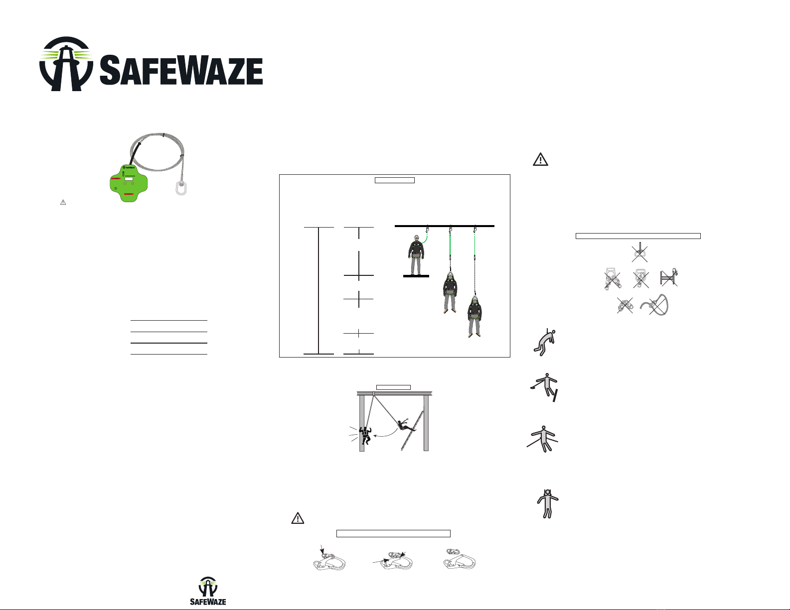
Lanyard Length
(6’ Total)
Deceleration
distance (3.5’ total)
Height of harness dorsal
D-ring from
worker’s feet
(6’ total)
Safety factor
(2’ total)
Required
distance
from
Anchorage
(17.5’ total)
Fall Clearance: There must be sucient clearance below the anchorage connector to arrest a fall
before the user strikes the ground or an obstruction. When calculating fall clearance, account for a
MINIMUM 2’ safety factor, deceleration distance, user height, length of lanyard/SRL, and all other
applicable factors. (See Figure 1)
LIMITATIONS
Fall Clearance Diagram
***Diagram shown is an example
fall clearance calculation ONLY.
For all applications: worker weight capacity range
(including all clothing, tools, and equipment) is 130-310 lbs
FIGURE 1
Swing Falls: Prior to installation or use, make considerations for eliminating or minimizing all swing
fall hazards. Swing falls occur when the anchor is not directly above the location where a fall occurs.
Always work as close to in line with the anchor point as possible. Swing falls signicantly increase
the likelihood of serious injury or death in the even of a fall. (See Figure 2)
COMPATIBILITY OF CONNECTORS
Connectors are compatible with connecting elements when they have been designed to work together
in such a way that their sizes and shapes do not cause their gate mechanisms to inadvertently open
regardless of how they become oriented. Connectors (hooks, carabiners, and D-rings) must be
capable of supporting at least 5,000 lbs. (22.2 kN). Connectors must be compatible with the anchorage
or other system components (see Figure 4). Do not use equipment that is not compatible.
Non-compatible connectors may unintentionally disengage (see Figure 3). Connectors must be
compatible in size, shape, and strength. Self-locking snap hooks and carabiners are required by ANSI
Z359 and OSHA guidelines. Contact SAFEWAZE™ if you have any questions about compatibility.
FIGURE 3 - UNINTENTIONAL DISENGAGEMENT
3 - Gate opens
2 - Gate presses
against
non-compliant
part
4 - And parts
disengage.
1 - Non Compliant Part
NOTE: SOME SPECIALITY CONNECTORS HAVE ADDITIONAL
REQUIREMENTS. CONTACT SAFEWAZE™ WITH QUESTIONS.
FIGURE 2
FIGURE 4 - INAPPROPRIATE CONNECTIONS
MAKING CONNECTIONS
Snap hooks and carabiners used with this equipment must be double locking and/or twist lock. Ensure
all connections are compatible in size, shape and strength. Do not use equipment that is not compatible.
Ensure all connectors are fully closed and locked.
SAFEWAZE™ connectors (snap hooks and carabiners) are designed to be used only as specied
in each product’s user’s instructions. See gure 4 for examples of inappropriate connections. Do not
connect snap hooks and carabiners:
• To a D-ring to which another connector is attached.
• In a manner that would result in a load on the gate (with the exception of tie back hooks). NOTE:
Large snap hooks must not be connected to objects which will result in a load on the gate if the hook
twists or rotates. Snap hooks marked with ANSI Z359.12 and are equipped with a 3,600 lb (16 kN)
gate. Check the marking on your snap hook to verify its compatibility.
NOTE: Large throat snap hooks must not be connected to standard size D-rings or similar
objects which will result in a load on the gate if the hook or D-ring twists or rotates, unless
the snap hook complies with ANSI Z359.1-2007 or ANSI Z359.12 and is equipped with a
3,600 lb (16 kN) gate. Check the marking on your snap hook to verify that it is appropriate
for your application.
• In a false engagement, where features that protrude from the snap hook or carabiner catch on the
anchor, and without visual conrmation seems to be fully engaged to the anchor point.
• To each other.
• By wrapping the web lifeline around an anchor and securing to lifeline except as allowed for Tie Back
models.
• To any object which is shaped or sized in a way that the snap hook or carabiner will not close and
lock, or that roll-out could occur.
• In a manner that does not allow the connector to align properly while under load.
Using a connector that is undersized or irregular in shape (1) to connect a snap hook or carabiner could
allow the connector to force open the gate of the snap hook or carabiner. When force is applied, the gate
of the hook or carabiner presses against the non-compliant part (2) and forces open the gate (3). This
allows the snap hook or carabiner to disengage (4) from the connection point.
2053
SPECIFIC ANCHOR APPLICATIONS
Personal Fall Arrest: SafeWaze Drop Through Anchors are designed as
an anchor point to support a maximum of 1 Personal Fall Arrest System
(PFAS) when utilized for fall protection applications. The structure to
which the anchor is attached must withstand loads applied in the
directions permitted by the system of at least 5,000 lbs. Maximum
allowable free fall is 6’.
Restraint: SafeWaze Drop Through Anchors are authorized for use in
Restraint applications. The structure to which the anchor is attached must
withstand loads applied in the directions permitted by the system of at
least 1,000 lbs NO free fall is permitted. Restraint systems may only be
used on surfaces with slopes up to 4 / 12 (vertical / horizontal). For
Restraint applications, the allowable attachment points to harness are
Dorsal D-ring, Chest D-ring, Side D-rings, and Shoulder D-rings.
Work Positioning: SafeWaze Drop Through Anchors are authorized for
use in Work Positioning applications. Work Positioning allows a worker
to be supported during suspension while freeing both hands to conduct
work operations. The structure to which the Anchor is attached must
withstand loads applied in the directions permitted by the system of at
least 3,000 lbs. Maximum allowable free fall is 2’. For positioning
applications, the allowable attachment points to harness are the Side
D-rings.
Rescue/Conned Space: SafeWaze Drop Through Anchors are
authorized for use in Rescue/Conned Space applications. Rescue
systems are utilized to safely recover a worker from a conned location or
after exposure to a fall. Composition of rescue systems can vary based
upon the type of rescue involved. The structure to which the Anchor is
attached must withstand loads applied in the directions permitted by the
system of at least 3,000 lbs. NO free fall is permitted. For rescue
applications, the allowable attachment points to harness are Dorsal
D-ring, Chest D-ring and Shoulder D-rings.
All above referenced applications have a worker weight capacity range of 310 lbs
(including all clothing, tools, and equipment).
Drop Through Anchor
Complies with OSHA1910.66, OSHA 1926.502, ANSI Z359.1-2007
020-4020 (2’/ .61m)
020-4021 (8.5’ / 2.6m)
Donot use in wet or uncured
concrete. Use in normal weight
concretewith a compression
strengthof at least 3,000 PSI
(20.7MPa). UseONLYon
concretedecks with a minumum of
4”thickness. Thisanchor is to be
usedin an overhead application
ONLY.
Allpersons using this equipment
mustread, understand, and follow
allinstructions. Failureto do so
mayresult in serious injury or
death.
Useonly compatible connectors. Avoidall physical hazards including thermal, electrical
andchemical sources. Inspectbefore each use. Inaddtion,a competent
personmust inspect this equipment at least annually.
DO NOT TOUCH FALL
PROTECTION
ANCHOR WHEN IN
USE!
Materials:Coated Steel,
StainlessSteel, Galvanized
AircraftCable
020027
Min.Hole Diameter for Installation: 1-3/4” (4.445 cm)
Max.Hole Diameter for Installation: 6” (15.24 cm)


