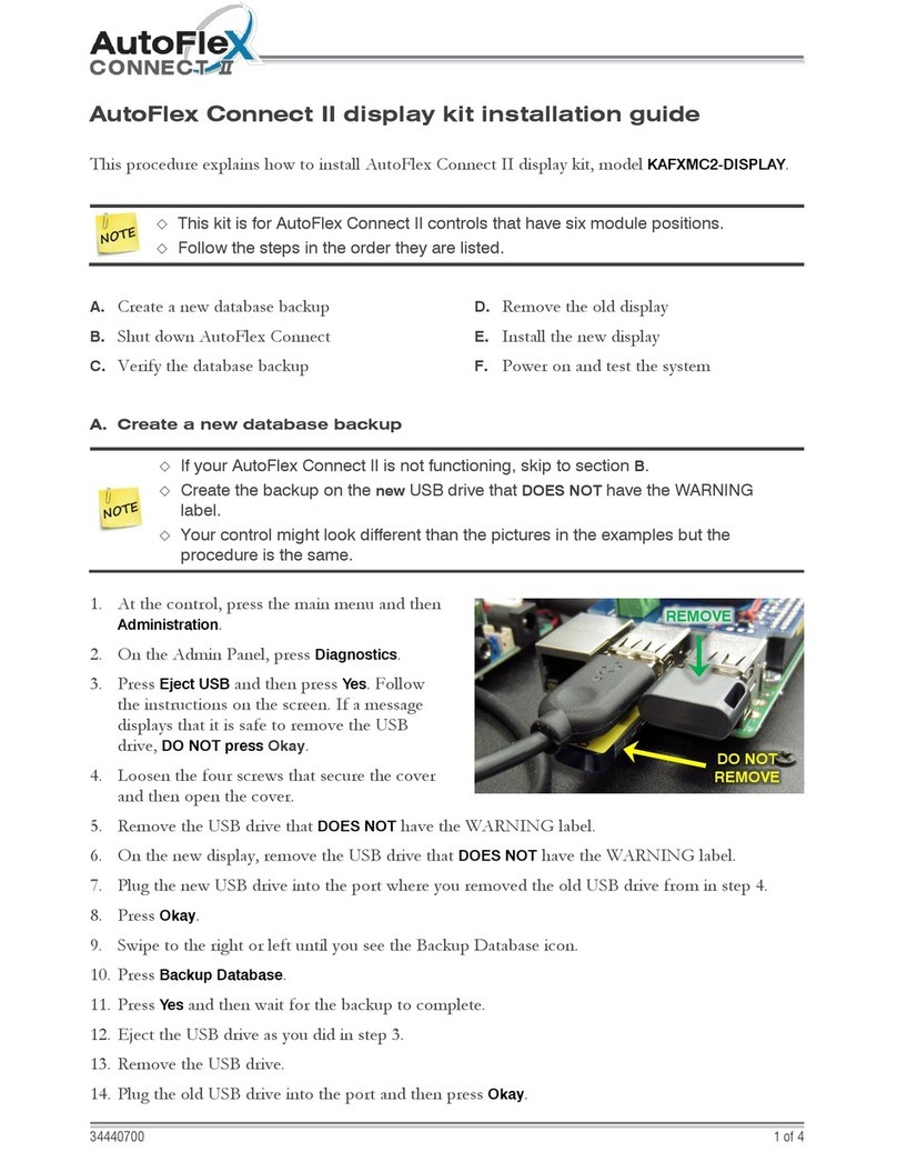
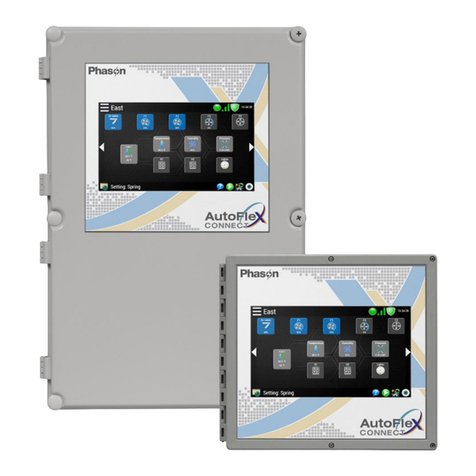
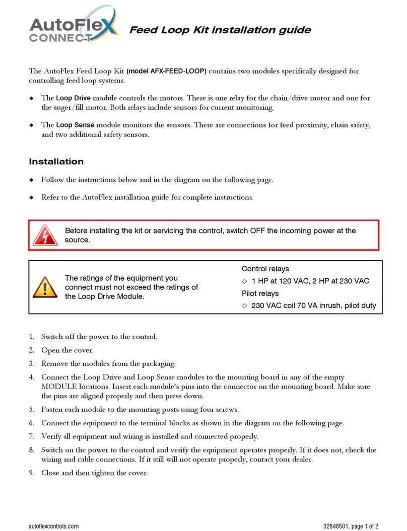
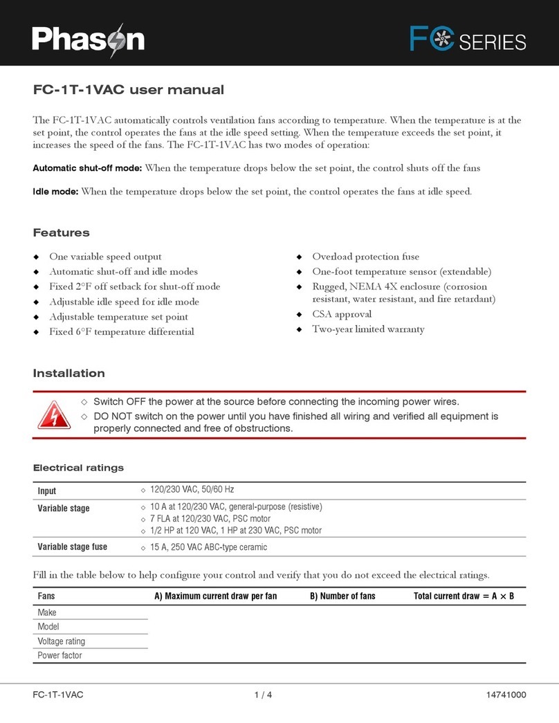
Phason AutoFlex Connect User manual


Copyright Phason Inc. Printed in Canada
All rights reserved. 32943003
Table of contents
Chapter 1: Introduction ..................................................................................................... 4
Introducing AutoFlex Connect .................................................................................................................. 4
Features ................................................................................................................................................ 4
Available modules ................................................................................................................................. 5
Chapter 2: Installation ....................................................................................................... 7
What you need to know before installing.................................................................................................. 7
Understanding power surges and surge suppression ......................................................................... 7
Reducing electrical noise using filters .................................................................................................. 8
Electrical ratings.................................................................................................................................... 9
Using power contactors to increase the capacity of relays .................................................................. 9
Enclosure dimensions and mounting guidelines.................................................................................. 9
AutoFlex layout.................................................................................................................................... 11
AutoFlex Mini layout ............................................................................................................................ 12
Connecting equipment to modules ........................................................................................................ 13
Connecting equipment to Actuator Modules...................................................................................... 13
Connecting sensors and devices to Input Modules ........................................................................... 15
Connecting equipment to Relay Modules........................................................................................... 18
Connecting equipment to Variable AC Modules................................................................................. 20
Connecting equipment to Variable Chimney Modules ....................................................................... 21
Connecting equipment to Variable DC Modules ................................................................................ 22
Connecting an alarm system .............................................................................................................. 23
Connecting the power source............................................................................................................. 25
Finishing the installation.......................................................................................................................... 25
Chapter 3: Network configuration................................................................................... 26
Remote access........................................................................................................................................ 26
UPnP security tips ............................................................................................................................... 27
Networking options ................................................................................................................................. 27
IP addressing: DHCP or static IP ........................................................................................................ 28
Port forwarding: UPnP or manual forwarding..................................................................................... 29
Chapter 4: Getting started............................................................................................... 31
Logging in ............................................................................................................................................... 31
Getting around ........................................................................................................................................ 32
Create users............................................................................................................................................ 32
Select the AutoFlex type ......................................................................................................................... 33
Select the units of measure..................................................................................................................... 33
Creating zones ........................................................................................................................................ 34
Checking for modules............................................................................................................................. 34
Assigning hardware to zones.................................................................................................................. 35
Adjusting the zone set point ................................................................................................................... 35
Adjusting equipment settings ................................................................................................................. 36
Using the Home page ............................................................................................................................. 36
Appendixes ..................................................................................................................... 37
Appendix A: Troubleshooting ................................................................................................................. 37
Appendix B: Calibrating and troubleshooting actuators......................................................................... 39

Copyright Phason Inc. Printed in Canada
All rights reserved. 32943002
Calibrating actuators ........................................................................................................................... 39
Determining correct actuator feedback wiring.................................................................................... 40
Appendix C: Additional modules and repair kits .................................................................................... 41
Appendix D: Understanding port forwarding.......................................................................................... 43
How your router handles requests and uses ports............................................................................. 43
Why you need to forward ports........................................................................................................... 44
Considerations before configuring your router................................................................................... 46
Index................................................................................................................................ 51

Introducing AutoFlex Connect
4
Chapter 1: Introduction
Introducing AutoFlex Connect
AutoFlex Connect brings flexibility and versatility to your fingertips. AutoFlex controls provide an
intuitive touchscreen interface at the control. Not at the control? No problem. AutoFlex Connect is
accessible from any web-enabled device. No matter where you are, your AutoFlex Connect controls
are always within reach.
AutoFlex controls are modular, meaning you have the flexibility to choose only what you need.
Choose from modules for sensor monitoring, or for relay, variable AC, or variable DC control. If
your needs change, your AutoFlex can easily change.
Features
Intuitive user interface
Local configuration and monitoring using
the 10-inch touchscreen display
Remote configuration and monitoring from
any web-enabled device
Easy expansion with modular design
Standard interchangeable modules for
control of fixed and variable speed fans,
heaters, inlets, and curtains
Sixteen available zones for control
and monitoring
Primary and secondary control
modifiers, including:
Temperature
Humidity
Static pressure
Carbon dioxide (CO2)
Ammonia (NH3)
Light level
THI
Wind speed
Windchill
Rain
Limited warranty (2 years)

5
11.85 in. (30 cm)
3.95 in. (10 cm)
11 in. (28 cm)
14.9 in. (37.8 cm)
7.1 in. (18.0 cm)
22.0 in. (55.9 cm)
AutoFlex controls are available in two models:
AutoFlex Connect AutoFlex Connect Mini
Room for 14 modules Room for 6 modules
NEMA 4X enclosure (22 x 15 x 7 in.) NEMA 4X enclosure (11 x 11.85 x 3.95 in.)
Available modules
Actuator Module (model ACT-1)
The Actuator Module has an open and a close relay for controlling actuators or
curtain machines. The Actuator Module includes a potentiometer feedback
connection.
For installation information, read Connecting equipment to Actuator Modules
on page 13.
Input Module (model IN-4)
The Input Module has connections for four analog sensors.
For installation information and a list of supported sensors, read Connecting
sensors and devices to Input Modules on page 15.

Introducing AutoFlex Connect
6
Current Sensing Relay Module (model RM-2)
The RM-2 Current Sensing Relay Module has two high-capacity, general-
purpose relays for controlling fans, heaters, lights, or any other equipment that
can be either on or off. Each relay includes a current sensor.
For installation information, read Connecting equipment to Relay Modules on
page 18.
Relay Module (model RM-4)
The RM-4 Relay Module has four general-purpose relays. The RM-4 does not
have current sensors.
For installation information, read Connecting equipment to Relay Modules on
page 18.
Variable AC module (model VAC-1)
The Variable AC Module has one variable output for controlling fans, heat
lamps, and heat mats. A temperature probe connector is included for heat mat
control. There is also a connection for a Single-Phase Slave.
For installation information, read Connecting equipment to Variable AC
Modules on page 20.
For information about Single-Phase Slave units, visit www.phason.ca.
Variable Chimney Module (model VCM-DC)
The Variable Chimney Module has two DC-signal outputs (0 to 10 V) for
controlling a chimney fan and damper. There is also an input for connecting a
measuring fan.
For installation information, read Connecting equipment to Variable Chimney
Modules on page 21.
Variable DC Module (model VDC-4)
The Variable DC Module has four DC-signal outputs (0 to 10 V) for
controlling equipment such as variable frequency drives.
For installation information, read Connecting equipment to Variable DC
Modules on page 22.

7
Chapter 2: Installation
What you need to know before installing
If you do not install external surge suppression devices, you risk damage to the
electronics inside the control, which may cause the control to fail.
Because it is not possible to completely protect this product internally from the
effects of power surges and other transients, we highly recommend that you
install external surge suppression devices. For specific recommendations, see
your electrical contractor.
If you do not take these precautions, you acknowledge your willingness to
accept the risk of loss or injury.
You can connect more than one piece of equipment to a variable stage or relay
as long as they are the same type (for example, two fans) and the total current
draw and horsepower does not exceed the relay’s limit.
The maximum wire gauge for all terminals is 12 AWG, solid or stranded.
Understanding power surges and surge suppression
Power surges can be caused by external influences (outside the barn –for example, lightning or
utility distribution problems) or they can be caused internally (inside the barn –for example, starting
and stopping inductive loads such as motors).
One of the most common causes of power surges is lightning. When lightning strikes the ground, it
produces an enormously powerful electromagnetic field. This field affects nearby power lines, which
transmit a surge to any device connected to it, such as lights, computers, or environmental controls
like the control. Lightning does not have to actually strike a power line to transmit a surge.
Surge suppression devices offer some protection from power surges. Because it is not possible to
internally protect this product completely from the effects of power surges and other transients,
Phason highly recommends that you install external surge suppression devices. For specific
recommendations, see your electrical contractor. If you do not take these precautions, you
acknowledge your willingness to accept the risk of loss or injury.

What you need to know before installing
8
Reducing electrical noise using filters
Electrical noise is caused by high voltage transients created when inductive loads, such as power
contactors, are switched on or off. The strength of the transients can be over 1000 volts and can
vary with the type of equipment and wiring, as well as several other factors.
Symptoms of electrical noise include erratic control operation, cycling inlets, communication
problems, and more. However, the effects of electrical noise are not always visible. Over time,
electrical noise can cause electronic circuits, relay contacts, and power contactors to deteriorate.
Phason highly recommends installing filters on all inductive loads.
Installing filters helps extend the life of equipment
Filters help prevent electrical noise problems by absorbing the transient energy. Even if you do not
have visible symptoms of electrical noise, filters help keep controls operating reliably and can extend
the life of the controls and equipment connected to them.
Phason’s snubber filters (part number 127-0) are for use with solenoids, timer relays, DC motors,
furnaces, and other equipment connected to the control’s relays. You can also use the filters with
loads connected to power contactors.
Install a filter in parallel with the load, as shown in the following example.
Do not use Snubber filters with variable stages.
Some power contactors include snubber filters. For more information, read
Using power contactors to increase the capacity of relays on page 9.
For more information about snubber filters or other Phason accessories, see
your dealer or visit www.phason.ca.

9
Electrical ratings
Control power 85 to 264 VAC, 50/60 Hz
Actuator Module 15 A at 120/230 VAC, general-purpose (resistive)
1/2 HP at 120 VAC, 1 HP at 230 VAC
RM-2 Relay Module 20 A at 120/230 VAC, general-purpose (resistive)
1 HP at 120 VAC, 2 HP at 230 VAC
RM-4 Relay Module 15 A at 120/230 VAC, general-purpose (resistive)
1/2 HP at 120 VAC, 1 HP at 230 VAC
Variable AC Module 7 A at 120/230 VAC, general-purpose (resistive)
4.9 FLA at 120/230 VAC, PSC motor
1/2 HP at 120 VAC, 1 HP at 230 VAC
800 W @ 120 VAC, 1600 W @ 230 VAC
Variable DC Module / 0 to 10 VDC, 2K Ω load
Variable Chimney Module (DC)
Alarm relay 0.4 A at 125 VAC; 2 A at 30 VDC, resistive load
0.2 A at 125 VAC; 1 A at 30 VDC, inductive load
Using power contactors to increase the capacity of relays
Phason’s 240-volt power contactors are heavy-duty relays that allow you to increase the load
handling capability of control relays. Power contactors are ideal for secondary ventilation fans and
electric heaters.
Phason’s power contactor relays have the following electrical ratings.
Coil 10.2 mA at 240 VAC
Contact 25 A at 240 VAC; resistive
2 HP at 240 VAC, 1 HP at 120 VAC; motor, power factor 0.4
1300 W at 120 VAC; tungsten
For more information about power contactors, visit www.phason.ca.
Enclosure dimensions and mounting guidelines
Mount the control on a sheltered, vertical surface.
Mount the control with the electrical knockouts facing down.
Mount the control away from sources of moisture and heat.

What you need to know before installing
10
AutoFlex
Mount high-voltage modules (Relay Modules, Actuator Modules, and Variable
AC Modules) next to the trough, and then run the cabling through the trough.
Mount low-voltage modules Input Modules, Variable Chimney Module - DC, and
Variable DC Modules) at the outer positions and run the cabling along the inside
of the enclosure.
AutoFlex Mini
Mounting holes (x5)
12 in.
12 in.
12 in. (30.5 cm)
12 in.
14.9 in. (37.8 cm)
7.1 in. (18.0 cm)
22.0 in. (55.9 cm)
11.85 in. (30 cm)
3.95 in. (10 cm)
11 in. (28 cm)
12 in. (30.5 cm)
12 in.
Mounting holes (x4)
12 in.
12 in.

11
AutoFlex layout
1
Mounting board: make sure all module boards, incoming power, and the ribbon cable from the communication
controller are properly connected.
2
Incoming power terminal: connect 120/230 VAC, 50/60 Hz power. See page 25.
3
Ground terminals: connect any equipment grounds to these terminals. See page 25.
4
12 VDC output terminal: connect any equipment that requires 12 VDC power, such as iWire radios. You cannot
connect VFDs here.
5
ON/OFF switch: switch the AutoFlex ON or OFF using this switch.
6
Cable trough: route AC power equipment cables through the trough. Route data and signal cables along the inner
walls of the enclosure.
7
Communication controller: make sure the ribbon cable is connected from the communication controller to the
mounting board.
8
Slave cable connection: connect an optional AutoFlex Slave unit here.
9
Alarm relay terminal: If you have an external alarm system, connect it here. See page 23.
10
Display controller: make sure the power supply (top board) is properly connected to the bottom board, and all
cables are properly connected.
11
USB drives: (appearance may vary) make sure the USB drives are properly connected to the USB ports.
12
USB cable: make sure the cable is properly connected from the display controller to the display board.
13
HDMI cable: make sure the cable is properly connected from the controller board to the display board.
13
2
11
6
1
3
10
8
5
4
9
7
12

What you need to know before installing
12
AutoFlex Mini layout
1
Mounting board: make sure all module boards, incoming power, and the ribbon cable from the communication
controller are properly connected.
2
Incoming power terminal: connect 120/230 VAC, 50/60 Hz power. See page 25.
3
Ground terminals: connect any equipment grounds to these terminals. See page 25.
4
12 VDC output terminal: connect any equipment that requires 12 VDC power, such as iWire radios. You cannot
connect VFDs here.
5
ON/OFF switch: switch the AutoFlex ON or OFF using this switch.
6
Communication controller: make sure the ribbon cable is connected from the communication controller to the
mounting board.
7
Slave cable connection: connect an optional AutoFlex Slave unit here.
8
Alarm relay terminal: If you have an external alarm system, connect it here. See page 23.
9
Display controller: make sure the power supply (top board) is properly connected to the bottom board, and all
cables are properly connected.
10
USB drives: (appearance may vary) make sure the USB drives are properly connected to the USB ports.
11
USB cable: make sure the cable is properly connected from the display controller to the display board.
12
HDMI cable: make sure the cable is properly connected from the controller board to the display board.
9
6
12
10
2
5
1
8
4
3
7
11

13
Connecting equipment to modules
You can connect more than one piece of equipment to a variable stage or relay
as long as they are the same type (for example, two fans) and the total current
draw and horsepower does not exceed the relay’s limit.
The maximum wire gauge for all terminals is 12 AWG, solid or stranded.
Connecting equipment to Actuator Modules
The Actuator Module (model ACT-1) has one OPEN and one CLOSE relay and a connection for
potentiometer feedback. You can connect an actuator or a curtain machine to an Actuator Module.
The ratings of the actuator or curtain machine must not exceed the relay ratings of
the Actuator Module.
15 A at 120/230 VAC, general-purpose (resistive)
1/2 HP at 120 VAC, 1 HP at 230 VAC
Actuators
Actuator control is for equipment that opens and closes, and positions to an exact location. For
example, inlets can be open between 0 and 100 percent. Actuators use a feedback potentiometer to
indicate their position to the control.
Feedback potentiometers
Each actuator you connect must have a feedback potentiometer. The feedback potentiometer, which
you connect to INPUT terminal on the Actuator Module, lets the control know how far the
actuator’s arm is extended.
Most linear actuators are available with potentiometer feedback and internal adjustable limit
switches. A 10,000 ohm, 10-turn feedback potentiometer is preferred, but the internal feedback
potentiometer can range between 1000 and 20,000 ohms. Potentiometers outside of this range will
affect the precision to which the control can control the actuator.
A system operates more precisely when using the largest amount of stroke that is
feasible with the actuator. The stroke is the distance the actuator arm extends or
retracts.

Connecting equipment to modules
14
Curtain machines
Curtains are usually controlled by equipment called curtain machines (sometimes referred to as
winches). Curtains are opened and closed to let in more air or less air, the idea being more air cools
the building. Curtain machines use a timer and do not have a feedback potentiometer.
To connect actuators
1. Connect actuators to the control as shown below. Refer to your actuator’s installation guide for
information about its power supply requirements.
2. Calibrate the actuator. You can calibrate by pressing the CALIBRATE button, or using the
display. For more information the calibration process, and instructions for calibrating using the
display, read Calibrating actuators on page 39.
AC powered actuators DC powered actuators
When routing the actuator feedback wires, do not run them in or along the same
conduit as AC-power lines.
If you are unsure of the potentiometer wiring for your actuator, read Determining
correct actuator feedback wiring on page 40.
If you are measuring AC power with a digital multimeter (DMM) and a limit switch
opens the circuit, the DMM measures voltage after the relay switch even if the
relay is open.

15
To connect curtain machines
Connecting sensors and devices to Input Modules
The Input Module (model IN-4) has connections for four analog sensors, dry contact switches, or
pulse output relays.
Compatible sensors and devices
Phason sensors
DOL sensors
3K temperature probes
Relative Humidity Sensor
Static Pressure Sensor
Wind Speed Sensor
Phason Rain Sensor
all models
models RHS and RHS-P
model SPS-2
model WINDSPEED-03
model PRS
Temperature and humidity
Temperature
Carbon dioxide (CO2)
Ammonia (NH3)
Light level
model DOL 114
4 - 20 mA version only
model DOL 15
model DOL 19
4 - 20 mA version only
model DOL 53
model DOL 16
100/1000 lux version only
Other devices
Dry contact pulse output, for example a water meter with pulse output
Dry contact digital switch, for example a door contact
Guidelines for connecting sensors
Do not run the sensor cable in the same conduit as AC power cables
Do not run the sensor cable beside AC power cables or near electrical equipment.
When crossing other cables or power lines, cross them at a 90-degree angle.

Connecting equipment to modules
16
Wired connections and shunt positions
1. Place the shunts in the proper positions for the type of sensor you are connecting. For each
sensor, there are four shunts to position.
2. Connect the wiring for the sensor.
Phason sensors
3K temperature probe Relative Humidity Sensor Static Pressure Sensor
Wind Speed Sensor Phason Rain Sensor

17
DOL sensors
DOL 114 temperature only DOL 114 humidity only DOL 114 temp. and humidity
DOL 15 temperature DOL 19 carbon dioxide (CO2) DOL 53 ammonia (NH3)
The DOL 19 carbon dioxide and DOL 53 ammonia sensors require external power
supplies. For more information, refer to the installation guides for those products.
DOL 16 light sensor, 100 lux DOL 16 light sensor, 1000 lux

Connecting equipment to modules
18
Other devices
Dry contact pulse output Dry contact digital switch
Connecting equipment to Relay Modules
Relay Modules have general-purpose relays for connecting equipment that is either on or off.
Examples include heaters, furnaces, single-speed fans, and lights. You can also use a relay as a
disconnect switch for a 0 to 10 VDC device.
The RM-2 Relay Module has two high-capacity relays. Each relay has a current sensor.
The RM-4 Relay Module has four relays. The RM-4 does not have current sensors.
For curtain machines, read Connecting equipment to Actuator Modules on page 13.
The ratings of the equipment you connect must not exceed the ratings of the Relay
Module.
RM-2
20 A at 120/230 VAC,
general-purpose (resistive)
1 HP at 120 VAC, 2 HP at 230 VAC
RM-4
15 A at 120/230 VAC,
general-purpose (resistive)
1/2 HP at 120 VAC, 1 HP at 230 VAC
Gas furnaces using hot-surface ignition or glow plugs can draw more current than
indicated on their nameplate and require power contactors. For more information,
contact your furnace dealer.

19
To connect equipment to Relay Modules
Gas furnaces
All other equipment
thermostat
inputs
thermostat
inputs

Connecting equipment to modules
20
Connecting equipment to Variable AC Modules
The Variable AC Module has one variable output for controlling fans, heat mats, heat lamps, or
similar equipment. A temperature probe connector is included for heat mat control. There is also a
connection for a Single-Phase Slave (model PSU-20).
The ratings of the equipment
you connect must not exceed
the ratings of the Variable AC
Module.
7 A at 120/230 VAC, general-purpose (resistive)
4.9 FLA at 120/230 VAC, PSC motor
1/2 HP at 120 VAC, 1 HP at 230 VAC
800 W at 120 VAC, 1600 W at 230 VAC
To connect heat mats
When connecting heat mats, you must connect a temperature probe for the master mat.
To connect variable speed fans or heat lamps
Other manuals for AutoFlex Connect
1
This manual suits for next models
1
Table of contents
Other Phason Control System manuals

Phason
Phason AutoFlex Connect II User manual

Phason
Phason PEC Plus User manual

Phason
Phason FC Series User manual

Phason
Phason PEC Plus User manual

Phason
Phason FC Series User manual

Phason
Phason AutoFlex Connect AFX-FEED-LOOP User manual

Phason
Phason AutoSort Connect User manual

Phason
Phason Supra Touch Series User manual

Phason
Phason AutoFlex Connect User manual

Phason
Phason PEC Plus User manual