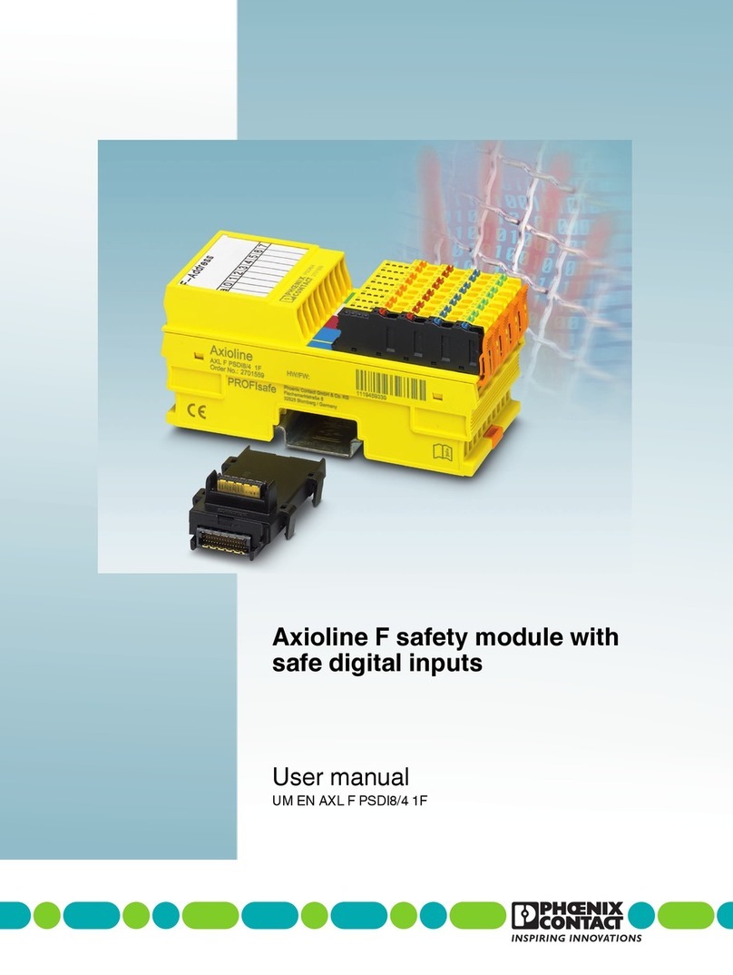
AXL F PSDO8/3 1F
6PHOENIX CONTACT 105739_en_04
4 Assembly, removal, and electrical installation...........................................................................27
4.1 Assembly and removal ........................................................................................ 27
4.1.1 Unpacking the module ......................................................................... 27
4.1.2 Preparation and assembly ................................................................... 27
4.1.3 Setting the DIP switch .......................................................................... 28
4.1.4 Mounting and removing the module ..................................................... 29
4.2 Electrical installation ............................................................................................ 31
4.2.1 Electrical installation of the Axioline F station ....................................... 31
4.2.2 Electrical installation of the module ...................................................... 31
5 Parameterization of the module ................................................................................................33
5.1 Setting the F-Parameters and i-Parameters......................................................... 33
5.2 Parameterization of the safe outputs ................................................................... 34
5.3 Behavior of the outputs in the event of enabled switch-off delay
for stop category 1............................................................................................... 35
6 Connection examples for safe outputs......................................................................................37
6.1 Explanation of the examples................................................................................ 37
6.2 Notes on the protective circuit of external relays/contactors
(freewheeling circuit) .......................................................................................... 38
6.3 Measures to achieve a specific safety integrity.................................................... 39
6.4 Single-channel assignment of safe outputs ......................................................... 40
6.5 Two-channel assignment of safe outputs ............................................................ 43
7 Startup and validation ...............................................................................................................47
7.1 Initial startup ........................................................................................................ 47
7.1.1 Startup mode ....................................................................................... 48
7.2 Restart after replacing a module.......................................................................... 49
7.2.1 Replacing a module ............................................................................. 49
7.2.2 Restart ................................................................................................. 49
7.3 Validation............................................................................................................. 49
8 Errors: messages and removal .................................................................................................51
8.1 Reading diagnostic messages............................................................................. 51
8.1.1 DiagState object 0x0018 ...................................................................... 53
8.1.2 DiagStateChannelNo object 0x0033 .................................................... 53
8.1.3 DiagStateAddValue object 0x0034 ...................................................... 54
8.1.4 ResetDiag object 0x0019 ..................................................................... 54
8.1.5 Examples for reading a diagnostic message ........................................ 55
