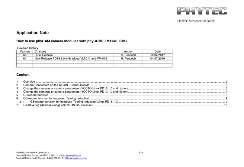
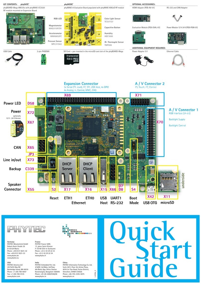
Phytec miniMODUL-537 User manual

A product of a PHYTEC Technology Holding company
miniMODUL-537
Hardware Manual
Edition November 1993

miniMODUL-537
PHYTEC Meßtechnik GmbH 1993 L-006e_2
In this manual are descriptions for copyrighted products that are not explicitly
indicated as such. The absence of the trademark () and copyright () symbols
does not imply that a product is not protected. Additionally, registered patents and
trademarks are similarly not expressly indicated in this manual.
The information in this document has been carefully checked and is believed to be
entirely reliable. However, PHYTEC Meßtechnik GmbH assumes no
responsibility for any inaccuracies. PHYTEC Meßtechnik GmbH neither gives
any guarantee nor accepts any liability whatsoever for consequential damages
resulting from the use of this manual or its associated product. PHYTEC
Meßtechnik GmbH reserves the right to alter the information contained herein
without prior notification and accepts no responsibility for any damages which
might result.
Additionally, PHYTEC Meßtechnik GmbH offers no guarantee nor accepts any
liability for damages arising from the improper usage or improper installation of
the hardware or software. PHYTEC Meßtechnik GmbH further reserves the right
to alter the layout and/or design of the hardware without prior notification and
accepts no liability for doing so.
Copyright 2001 PHYTEC Meßtechnik GmbH, D-55129 Mainz.
Rights - including those of translation, reprint, broadcast, photomechanical or
similar reproduction and storage or processing in computer systems, in whole or
in part - are reserved. No reproduction may occur without the express written
consent from PHYTEC Meßtechnik GmbH.
EUROPE NORTH AMERICA
Address: PHYTEC Technologie Holding AG
Robert-Koch-Str. 39
D-55129 Mainz
GERMANY
PHYTEC America LLC
255 Ericksen Avenue NE
Bainbridge Island, WA 98110
USA
Ordering
Information: +49 (800) 0749832
order@phytec.de 1 (800) 278-9913
info@phytec.com
Technical
Support: +49 (6131) 9221-31
support@phytec.de 1 (800) 278-9913
support@phytec.com
Fax: +49 (6131) 9221-33 1 (206) 780-9135
Web Site: http://www.phytec.de http://www.phytec.com
2nd Edition November 1993

Contents
PHYTEC Meßtechnik GmbH 1993 L-006e_2
Contents
Information for the miniMODUL-537.......................................................1
1 Introduction .........................................................................................1
2 Installation and Setting into Operation.............................................3
2.1 The Serial Interface ......................................................................4
2.2 The RESET...................................................................................5
2.3 The PC/AT Communication-Program..........................................5
2.4 Malfunctioning of the PC/AT.......................................................6
2.5 Installation of User-Programs on the miniMODUL-537 .............6
3 Pin Configuration................................................................................7
4 Memory Configuration and Address-Decoding.............................19
4.1 Standard-Memory-Configuration...............................................19
4.2 Von-Neumann-Memory-Configuration......................................20
4.3 The Individual Memory-Configurations ....................................20
4.4 External Extensions with more Memory-Chips .........................20
4.4.1 Application of an External DIL-EPROM......................21
4.4.2 Application of an EEPROM..........................................21
4.5 Address Decoding.......................................................................22
4.6 Hints for Memory Utilization.....................................................22
4.7 The Power-On-Jump-Option......................................................23
4.7.1 The Realization of User Programs in
Power-On-Jump-Mode..................................................24
4.7.2 Program Example..........................................................24
5 Jumper Description...........................................................................25
5.1 Jumper for Address Selection.....................................................26
5.2 Jumper for Controller Pre-Configuration...................................29
5.3 Jumper for Power-Down-Operation...........................................30
5.4 Jumper for Connection of the Interface Driver ..........................31
6 The Serial Interfaces .........................................................................33
6.1 The Special-Function-Register of SERIAL0..............................33
6.2 The Baud Generator of SERIAL0..............................................34
6.3 The Special-Function-Register of SERIAL1..............................36
6.4 The Baudrate-Generator of SERIAL1........................................37
6.5 The Connection to the Interface Driver......................................37
6.5.1 Connections of the RS-485-Interface Pre-Configured..38
6.5.2 Connections of the RS-232-Interface Pre-Configured..38
6.5.3 The Pin Assignment of the Interface for the
miniMODUL-537..........................................................39

miniMODUL-537
PHYTEC Meßtechnik GmbH 1993 L-006e_2
6.6 General Remarks for RS-232 and RS-485 Interfaces ................39
6.6.1 RS-232 Interface ...........................................................39
6.6.2 RS-485-Interface...........................................................40
6.7 Changing from RS-232 to RS-485 Standard..............................40
6.8 Program Example for the Serial Interface..................................41
6.8.1 Program for SERIAL0 ..................................................41
6.8.2 Program for SERIAL1 ..................................................42
7 RAM-Write-Protection and Battery Back-up................................43
7.1 Function of the Battery Buffering and Write Protection............44
7.2 Hints for the Utilization of the Battery Buffering......................45
8 The External Watchdog-Timer and the Power-Fail-Option ........47
8.1 The External Watchdog-Timer...................................................47
8.2 The Watchdog- and RESET-Time-Base....................................48
8.3 Application of the Power-Fail-Input (PFI..................................48
9 A/D Converter of the SAB80C537...................................................49
10 The RESET-Signal............................................................................51
11 The Optional Real-Time-Clock RTC72421....................................53
11.1 Selection of the RTC..................................................................53
11.2 Programming of the Clock.........................................................54
11.3 The Standard Pulse-Option ........................................................54
11.4 Description of the Control-Bits..................................................55
Index............................................................................................................57
Index of Figures
Figure 1: Dimensions of the miniMODUL-537 ..........................................2
Figure 2: Pin Connection .............................................................................7
Figure 3:The terminals of the miniMODUL-537.....................................18
Figure 4: Jumper ........................................................................................31

Information
PHYTEC Meßtechnik GmbH 1993 L-006e_2
Information for the miniMODUL-537
For the standard Version of this module with EPROM from 0000H
(plain Monitor-Mode or user machine program) the diode besides
JP2/JP7 at the bottom side of the circuit board should not be installed.
This is only required in combination with our Monitor-Basic. To make
possible a change of the module, this diode is soldered only at one end
for a redesign of the layout, except if there are no demands from you
otherwise.
Therefore there is no defect of our product because the diode is
soldered only at one end.

miniMODUL-537
PHYTEC Meßtechnik GmbH 1993 L-006e_2

Introduction
PHYTEC Meßtechnik GmbH 1993 L-006e_2 1
1Introduction
The miniMODUL-537 from PHYTEC is a universal microcontroller
board of credit-card size for applications in measuring and
Control Engineering.
The miniMODUL-537 with the microcontroller SAB80C537 is an
additional member of the credit-card size minicomputer series from
PHYTEC. The predecessors of this product are the miniMODUL-535
with the SAB80C535 microcontroller from Infineon and the
miniMODUL-552 with the microcontroller 80C552 from
VALVO/PHILIPS. All controllers are based on the architecture of the
8051 microcontroller family and have in general compatible
instruction sets. As developing tools, all assembler and compiler for
the 8051-family can be applied.
All those processors contain considerable extensions of the integrated
peripherals as there are interfaces, timer, A/D converter and parallel
ports. The external components like RAM, ROM, Real-Time Clock,
decoder, battery back-up and monitor are already available on the
miniMODUL-537 with modern SMD technique.
The miniMODUL-537 is a complete microprocessor-system with
versatile peripheral functions, and the necessity to develop a digital
microprocessor system for the application hardware can be avoided.
The miniMODUL-537 is plugged on to the application hardware,
which might be not very extensive, like a “big chip”.
The favorable cost-performance ratio liberates you from development,
design and test of a digital system.

miniMODUL-537
2PHYTEC Meßtechnik GmbH 2001 L-006e_2
For the 8051-family various assembler and compiler are available on
the market. PHYTEC offers for simple programming of the module a
Basic-interpreter and a monitor program. In the simplest instance only
a terminal is required, since the interface drivers are already
implemented. With the help of a PC the up/downloading of programs
is possible during the test phase. In combination of user PC-software
with C51, A51 and DSCOPE51 efficient program developing is
possible.
Figure 1: Dimensions of the miniMODUL-537

Installation and Setting into Operation
PHYTEC Meßtechnik GmbH 1993 L-006e_2 3
2Installation and Setting into Operation
The miniMODUL-537 requires a stabilized supply voltage of 5 V. The
current consumption is less 100 mA. Please employ only reliable
voltage regulators (for example 7805), since overvoltages might be
produced by bad power supplies or laboratory power supplies with
adjustable voltage, and damage the module. The connections of the
supply voltage are found in diagonal corners of the module. The
printing on the board designates GND with ’-’and VCC with ’+’.
The following pins are connected to VCC or GND:
A1, A2, B1, B2 - VCC
A63, A64, B63, B64 - GND
The connection of one point is sufficient for example VCC to A1 and
GND to B1.
The supply voltage should not decrease below 4.8 V. Otherwise a
reset might automatically be triggered, which stops all operations. In
case of problems, check if the supply voltage is to low. Also short
voltage fluctuations have to be considered.

miniMODUL-537
4PHYTEC Meßtechnik GmbH 2001 L-006e_2
2.1 The Serial Interface
If an EPROM was installed by the manufacturer, usually all jumpers
are configured properly. In order to communicate with our Monitor-
program or Monitor-Basic, the connections of the RS-232 interface
A45, A47 with a terminal or PC/AT are required. Those programs
don’t use handshake-lines, since they are operating with XON/XOFF
protocol. Connect the RS-232-input A45 with the RS-232-output of
your PC/AT or terminal and the RS-232-output A47 with the
corresponding input of the terminal or PC/AT. The standard RS-232
connection is especially designated on the printing of the circuit board.
The arrows symbolize the flow of the signals. Don’t forget the
GND-connection for example to A63.
The standard baud rate is 9600 baud. The transmission format is
8 data bit, no parity, one start bit and one stop bit.
In case of malfunctioning, check if RxD and TxD are exchanged. With
a usual voltage meter you can measure, if at the TxD-connection a
negative voltage between –7 V ..-12 V against GND is found. RxD
has a voltage of 0 V against GND.
Please connect always TxD with RxD and RxD with TxD. If
sometimes the transmission is failing, the GND-line might be
connected in the wrong way.

Installation and Setting into Operation
PHYTEC Meßtechnik GmbH 1993 L-006e_2 5
2.2 The RESET
The RESET is activated automatically at turn on. For an unfavorable
increase of the supply voltage eventually a manual RESET might be
required. Trigger this RESET by shorting the adjacent connections
A61 (/RESIN) and A63 (GND). Please maintain this connection for at
least half a second. The manual RESET doesn’t produce a continuous-
RESET, but equidistant RESET-pulses. A continuous-RESET is
achieved by the connection of A34 with GND. The connection should
not be bouncing. In order to recognize the connections easily, A61 and
A63 are signed with a square.
2.3 The PC/AT Communication-Program
Your PC/AT doesn’t notify the RS-232-interface, as long as no
corresponding program is started.
In order to display data from the miniMODUL-537 and to enter data
via the RS-232 interface, a communication program has to be started
on a PC/AT. Therefore we include the program MONTERM in the
software package of Monitor and Monitor-Basic. The invocation of
this program is achieved by the following command:
MT <cr> ; for 9600 baud
MT BAUDRATE (19200) <cr> ;for other baud rates (19200 baud)
After the start of MONTERM and a RESET of the miniMODUL-537
the message of the installed software should be displayed on the
screen.

miniMODUL-537
6PHYTEC Meßtechnik GmbH 2001 L-006e_2
2.4 Malfunctioning of the PC/AT
For the utilization of other PC-communication-programs as
MONTERM we don’t guarantee proper operation.
The miniMODUL-537 is only malfunctioning, if despite correct
jumper setting and with our standard EPROMs no output can be
observed at TxD of the miniMODUL-537 after a RESET. In case of
problems, check the signal with an oscilloscope at point A47.
The reason for no operation might be either a bad cable or
PC-interface or PC-software. A simple method to check the operation
of the PC is to connect TxD and RxD of the PC before the
miniMODUL-537 was separated. Actuation of a key at the PC will
result in the echo of this key displayed at the screen of the PC.
2.5 Installation of User-Programs on the miniMODUL-537
When installing user-programs on the module, pay attention to the
correct configuration of the jumpers, which are mostly found on the
back-side of the module. Those jumpers select the address regions, the
access mode and the chip-type for RAM, EPROM and eventually
EEPROM. Select the jumpers according to the description found in
section 5. The serial interfaces with RS-232 and RS-485 standard are
already connected from the controller to the corresponding ports. If
the port pins should be used for other purposes those conductor stripes
have to be cut. More detailed information of the serial interfaces is
found in section 6.

Pin Configuration
PHYTEC Meßtechnik GmbH 1993 L-006e_2 7
3Pin Configuration
Figure 2: Pin Connection
The miniMODUL-537 has two connecting strips A and B with
64 connections each. Here all connections for supply voltages, digital
signals and some control-lines are found. The analog-inputs and
reference voltages are positioned in the connecting stripe C. The pins
with uneven number are at the outside and the pins with even number
are at the inside.
The supply voltages GND and VCC are applied in diagonal on two
corners of the board. The printing on the board designates VCC by ’+’
and GND by ’-’. For uncritical applications, VCC and GND have to be
connected only once.
All signals with few exceptions are positioned efficiently and packed
analog to their function in the connection stripe. The printing on the
board shows lines to indicate the different functions and help to
recognize the proper connections of the ports. Bit 0 is signed with a
point ’.’. For detailed positioning of the remaining signals use the pin
assignment diagram.

miniMODUL-537
8PHYTEC Meßtechnik GmbH 2001 L-006e_2
Often used connections, like the serial interface 0, the RESET-input
and the RS-485-connections are especially signed with a quadrangle
The connections in detail
In the following, connections with the supplement ’TTL’ have
TTL level, but must not coincide in every respect to the TTL standard.
Notice, that the parallel ports have a characteristic output curve, which
differs from TTL-outputs. More information is found on page 61 of
the controller manual.
The supply voltage
A1, 2 and B1, 2 Supply voltage VCC of 5.0 V
A63,64 and B63,64 Digital Ground
A42 Battery voltage input 3 V
A32 Battery voltage output 3 V/ 5 V
C01..C21 Analog-GND VAGND
C23 Analog-reference voltage VAREF
Data-address bus
More detailed information of the performance, loading capacity and
DC-characteristic can be depicted from the INFINEON controller
manual of the SAB80C537, starting on page 61 and 336 respectively.
B10..B03 D0..D7 Data bus
B18..B11 A0..A7 Address bus low
B19,..,B26 A8..A15 Address bus high Attention counting!

Pin Configuration
PHYTEC Meßtechnik GmbH 1993 L-006e_2 9
The general controller ports
More detailed information of the performance, loading capacity and
DC-characteristic can be depicted from the INFINEON controller
manual of the SAB80C537, starting on page 61 and 336 respectively.
A30..A23 Port 1 (Ext. interrupts, timer 2-control)
A15..A22 Port 3 (Ext. int., timer 0/1-control, SERIAL0,/RD,/WR)
A03..A10 Port 4 (Compare-unit)
B52..B45 Port 5 (Concurrent-compare-unit)
B55..B62 Port 6 (AD-converter, SERIAL 1)
C10..C24 Port 7 (Analog-inputs AN00..AN07)
C02..C08 Port 8 (Analog-inputs AN08..AN10)
The exact pin assignment of the ports and their alternative functions
are described in the controller manual page 68 and the corresponding
sections.
Decoder-Control-Signals
The decoder-control-signals are only relevant in case an external
decoder is connected, which replaces the module-internal minimum
decoder.
B42 XROM ROM Decoder-selection
Input:open if no external address decoder to /XOEROM and
/XCEROM should be connected. Status LOW switches off the
module internal selection of the EPROM U11.
B41 /XOEROM ROM Output_Enable
Input/Output active LOW. Can be connected to an external address
decoder. For this purpose XROM must be connected permanently or
temporarily to LOW.

miniMODUL-537
10 PHYTEC Meßtechnik GmbH 2001 L-006e_2
A58 ROM A15 ROM A15
Input:Can be wired from outside for special purposes. Then jumper
JP9 must be open.
B38 XRAM2 RAM 2 (U12)-Decoder selection
Input:Open, if no external address decoder should be connected to
/XCERAM2. Status LOW switches off the modules internal
selection of RAM U12.
B37 /XCERAM2RAM 2 (U12) Chip-Enable
Input/Output active LOW. Can be connected to an external address
decoder. For this purpose XRAM2 must be connected permanently or
temporarily to LOW.
B40 XRAM1 RAM 1 (U13)-Decoder selection
Input:Open, if no external address decoder should be connected to
/XCERAM1. Status LOW switches off the module internal
selection of RAM U13.
B39 /XCERAM1RAM 1 (U13) Chip-Enable
Input/Output active LOW. Can be connected to an external address
decoder. For this purpose XRAM1 has to be connected permanently or
temporarily to LOW.
B43 XCEROM
Input/Output active LOW. Can be connected to an external address
decoder. For this purpose XROM has to be connected permanently or
temporarily to LOW.

Pin Configuration
PHYTEC Meßtechnik GmbH 1993 L-006e_2 11
Clock-Control-signals
A60 STDPStandardpulse of the optional Real-Time Clock
Output active LOW. Pulse 1/60 sec cycle, second cycle, minute cycle
or hour cycle. More information are taken from the data sheet
section 11 of the Real-Time Clock.
A59 /CSRTC Chip-Enable of the optional Real-Time Clock
Input active LOW. Can be connected with a vacant controller port or
an external address decoder.
RS-232-Driver connections
A47 T10 TxD 0 (Transmitter 1 Output)
Output for RS-232 for the serial interface SERIAL 0 of the
SAB80C537.
A41 T1I Transmitter 1 Input
Input:Already connected to TxD0 of the controller. For other utiliza-
tion, cut the connection with TxD0.
A45 R1I RxD 0 (Receiver 1 Input)
Input for RS-232 for the serial interface SERIAL0 of the SAB80C537.
A44 R10 Receiver 1 Output
Output:Already connected with RxD0 of the controller. For other
utilization, cut the connection with RxD0.

miniMODUL-537
12 PHYTEC Meßtechnik GmbH 2001 L-006e_2
Free RS-232-Driver connections
The following connections of the RS-232-driver chip are at one’s
disposal. They can be used for the second serial interface SERIAL1 or
for handshake-signals.
A49 R3I (RS-232) A50 R30 (TTL)
A55 R2I (RS-232) A54 R20 (TTL)
A45 R1I (RS-232) A44 R10 (TTL)
A56 T40 (RS-232) A52 T4I (TTL)
A48 T30 (RS-232) A51 T3I (TTL)
A46 T20 (RS-232) A43 T2I (TTL)
RS-485-Driver connections
B29 RS-485_VCC
Voltage supply for the RS-485-Driver chip. Can be switched on/off
externally if the connection is cut.
B31 RS-485-signal B
B33 RS-485-signal A
Inputs/Outputs that are the complementary data-signals to RS-485. For
connections with up to 31 other modules, don’t exchange A and B.
B30 D Transmit-data-input (TTL)
Already connected with TxD 1 at B57 (port 6.2)
For the utilization for other purposes of this driver please cut the
connection B30-B57.

Pin Configuration
PHYTEC Meßtechnik GmbH 1993 L-006e_2 13
B32 R Receive-data-output (TTL)
Already connected with RxD 1 to B56 (port 6.1)
For other applications of this driver please cut the connection
B32-B56.
B34 /R Inverse receive-data-output (TTL)
Already connected with A17 (port 3.2, /INT 0) for PHYNET.
For other applications of P3.2 open JP6.
B36 /RE RS-485-Receiver_Enable
Input:Already connected with B52 (port 5.0) for PHYNET.
For other applications of P5.0 cut connection B36-B52.
B35 /DE RS-485 Transmit-Enable
Input:Already connected with B51 (port 5.1) for PHYNET.
For other applications of P5.1 cut connection B35-B51
General Control signals
A57 ALE Address-Latch_Enable, see controller manual
A31/ PSEN Program_Store_Enable,see controller manual
A22/ RD (Port 3.7) see controller manual
A22/ WR (Port 3.6)see controller manual
A36/ WRO Write_Out
(Write-pulse unbuffered, can be turned-off)
Output active LOW. This signal corresponds to the /WR-signal, but
can be disabled by a RESET or the M-DIS-function. For missing
supply voltage this signal has no voltage.

miniMODUL-537
14 PHYTEC Meßtechnik GmbH 2001 L-006e_2
A37/ PWR Protected_Write (Write-pulse buffered, can be turned off)
Output active LOW. This signal corresponds to the /WR-signal, but
can be disabled by a RESET of the M-DIS-function. For missing
supply voltage, this signal has battery voltage and can therefore be
used for external components with battery buffering.
A61 /RESIN RESET-Input
Input active LOW. A connection with GND for about .5 sec. triggers a
RESET-pulse. Permanent connection causes a cyclic RESET-pulse
series of 1.6 sec duration. This input is not appropriate to stop the
controller for the duration of the activation of /RESIN.
A34 /RES RESET-Input/Output
Input/Output active LOW. This bi-directional connection might be
connected to GND. For the duration of this connection the controller
remains in the status of a continued RESET. The actuation of the /RES
should be bounce free. The slope of rising edge depends on the load
capacity.
A33 RES RESET-pulse output
Output active HIGH. This signal provides the inverse RESET-pulse of
/RES.
Attention:
An external RESET by wiring of A35 (/RES) doesn’t generate a signal
at A33. Only the RESET-pulses triggered by A61 will be present.
A13 BRESBattery-supplied RESET-signal
Output active HIGH. This signal is the inverse of /RES.
Table of contents
Other Phytec Microcontroller manuals

Phytec
Phytec i.MX6UR User manual

Phytec
Phytec phyCORE-i.MX31 User manual

Phytec
Phytec nanoModul-164 Programming manual

Phytec
Phytec phyCORE-MPC5200B tiny User manual

Phytec
Phytec IoT-Enablement-Kit 1 User manual

Phytec
Phytec SYS TEC ELECTRONIC CANopen Chip164 Programming manual

Phytec
Phytec LAN-087e.A2 phyCORE-i.MX 8 Alpha Kit User manual

Phytec
Phytec phyCORE-LPC3250 Programming manual

Phytec
Phytec phyCORE-SC520 User manual

Phytec
Phytec phyCORE-LPC3250 Programming manual