SDD ES PROFINET
Operating Manual SDD ES PROFINET
1003826-EN-01 9
}System description "Safety Device Diagnostics"
You will need to be conversant with the information in these documents in order to fully un-
derstand this operating manual.
Use of qualified personnel
The products may only be assembled, installed, programmed, commissioned, operated,
maintained and decommissioned by competent persons.
A competent person is a qualified and knowledgeable person who, because of their train-
ing, experience and current professional activity, has the specialist knowledge required. To
be able to inspect, assess and operate devices, systems and machines, the person has to
be informed of the state of the art and the applicable national, European and international
laws, directives and standards.
It is the company’s responsibility only to employ personnel who
}Are familiar with the basic regulations concerning health and safety / accident preven-
tion,
}Have read and understood the information provided in the section entitled Safety
}Have a good knowledge of the generic and specialist standards applicable to the spe-
cific application.
Warranty and liability
All claims to warranty and liability will be rendered invalid if
}The product was used contrary to the purpose for which it is intended,
}Damage can be attributed to not having followed the guidelines in the manual,
}Operating personnel are not suitably qualified,
}Any type of modification has been made (e.g. exchanging components on the PCB
boards, soldering work etc.).
Disposal
}When decommissioning, please comply with local regulations regarding the disposal of
electronic devices (e.g. Electrical and Electronic Equipment Act).
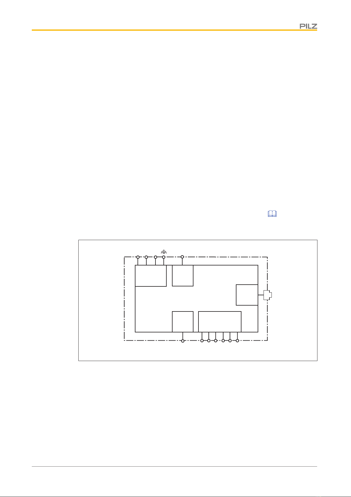
Function description
Operation
The SDD ES PROFINET is configured and started automatically after the supply voltage is
switched on.
LEDs indicate the status of the SDD ES PROFINET and communication between the safety
devices and the PROFINET IO controller.
The SDD ES PROFINET sends telegrams to the connected safety devices via a ring pro-
tocol.
The following types of data are transferred to the fieldbus and read in.
}Process data
– Information and commands on safety functions (OSSD, guard locking, …)