Pilz 774584 User manual

PZE X4V8
Operating Manual-1003204-EN-11
-Safety relays

Preface
This document is the original document.
Where unavoidable, for reasons of readability, the masculine form has been selected when
formulating this document. We do assure you that all persons are regarded without discrim-
ination and on an equal basis.
All rights to this documentation are reserved by Pilz GmbH & Co. KG. Copies may be made
for the user's internal purposes. Suggestions and comments for improving this documenta-
tion will be gratefully received.
Pilz®, PIT®, PMI®, PNOZ®, Primo®, PSEN®, PSS®, PVIS®, SafetyBUS p®,
SafetyEYE®, SafetyNET p®, the spirit of safety® are registered and protected trademarks
of Pilz GmbH & Co. KG in some countries.
SD means Secure Digital

Contents
Operating Manual PZE X4V8
1003204-EN-11 | 3
Introduction ............................................................................................................................4
Validity of documentation ..........................................................................................................4
Using the documentation ..........................................................................................................4
Definition of symbols .................................................................................................................4
Safety ......................................................................................................................................5
Intended use .............................................................................................................................5
Safety regulations .....................................................................................................................5
Safety assessment....................................................................................................................5
Use of qualified personnel.........................................................................................................6
Warranty and liability.................................................................................................................6
Disposal ....................................................................................................................................6
For your safety ..........................................................................................................................6
Unit features ...........................................................................................................................7
Safety features .......................................................................................................................7
Block diagram/terminal configuration .................................................................................7
Function description ..............................................................................................................8
Installation ..............................................................................................................................8
Wiring ......................................................................................................................................8
Preparing for operation .........................................................................................................9
Operation ................................................................................................................................10
Status indicators........................................................................................................................11
Faults – Interference ..............................................................................................................11
Dimensions in mm .................................................................................................................11
Technical details ....................................................................................................................12
Safety characteristic data..........................................................................................................15
Supplementary data ...............................................................................................................15
Service life graph ......................................................................................................................16
Order reference ......................................................................................................................16
EC declaration of conformity ................................................................................................16
UKCA-Declaration of Conformity .........................................................................................17

PZE X4V8
Operating Manual PZE X4V8
1003204-EN-11 | 4
Introduction
Validity of documentation
This documentation is valid for the product PZE X4V8. It is valid until new documentation is
published.
This operating manual explains the function and operation, describes the installation and
provides guidelines on how to connect the product.
Using the documentation
This document is intended for instruction. Only install and commission the product if you
have read and understood this document. The document should be retained for future ref-
erence.
Definition of symbols
Information that is particularly important is identified as follows:
DANGER!
This warning must be heeded! It warns of a hazardous situation that poses
an immediate threat of serious injury and death and indicates preventive
measures that can be taken.
WARNING!
This warning must be heeded! It warns of a hazardous situation that could
lead to serious injury and death and indicates preventive measures that can
be taken.
CAUTION!
This refers to a hazard that can lead to a less serious or minor injury plus
material damage, and also provides information on preventive measures
that can be taken.
NOTICE
This describes a situation in which the product or devices could be dam-
aged and also provides information on preventive measures that can be
taken. It also highlights areas within the text that are of particular import-
ance.

PZE X4V8
Operating Manual PZE X4V8
1003204-EN-11 | 5
INFORMATION
This gives advice on applications and provides information on special fea-
tures.
Safety
Intended use
The contact expansion module PZE X4V8 meets the requirements of EN 60947-5-1 and
EN 60204- 1. It is an expansion module for increasing the number of contacts available on
a base unit. Base units are all safety relays with feedback loop.
The max. achievable safety level depends on the base unit. The expansion module may not
exceed this. The safety-related characteristic values stated under safety-related character-
istic data [ 15] can only be achieved if the base unit also exhibits these safety charac-
teristic values.
Improper use
The following is deemed improper use in particular:
}Any component, technical or electrical modification to the product,
}Use of the product outside the areas described in this operating manual,
}Use of the product outside the technical details (see chapter entitled Technical
Details [ 12]).
NOTICE
EMC-compliant electrical installation
The product is designed for use in an industrial environment. The product
may cause interference if installed in other environments. If installed in other
environments, measures should be taken to comply with the applicable
standards and directives for the respective installation site with regard to in-
terference.
Safety regulations
Safety assessment
Before using a device, a safety assessment in accordance with the Machinery Directive is
required.
The product as an individual component fulfils the functional safety requirements in accord-
ance with EN ISO 13849 and ENIEC62061. However, this does not guarantee the func-
tional safety of the overall plant/machine. To achieve the relevant safety level of the overall
plant/machine’s required safety functions, each safety function needs to be considered sep-
arately.

PZE X4V8
Operating Manual PZE X4V8
1003204-EN-11 | 6
Use of qualified personnel
The products may only be assembled, installed, programmed, commissioned, operated,
maintained and decommissioned by persons who are competent to do so.
A competent person is a qualified and knowledgeable person who, because of their train-
ing, experience and current professional activity, has the specialist knowledge required. To
be able to inspect, assess and operate devices, systems and machines, the person has to
be informed of the state of the art and the applicable national, European and international
laws, directives and standards.
It is the company’s responsibility only to employ personnel who
}Are familiar with the basic regulations concerning health and safety / accident prevention,
}Have read and understood the information provided in the section entitled Safety
}Have a good knowledge of the generic and specialist standards applicable to the specific
application.
Warranty and liability
All claims to warranty and liability will be rendered invalid if
}The product was used contrary to the purpose for which it is intended,
}Damage can be attributed to not having followed the guidelines in the manual,
}Operating personnel are not suitably qualified,
}Any type of modification has been made (e.g. exchanging components on the PCB
boards, soldering work etc.).
Disposal
}In safety-related applications, please comply with the mission time TM in the safety-related
characteristic data.
}When decommissioning, please comply with local regulations regarding the disposal of
electronic devices (e.g. Electrical and Electronic Equipment Act).
For your safety
The unit meets all the necessary conditions for safe operation. However, please note the
following:
}Note for overvoltage category III: If voltages higher than low voltage (>50 VAC or >120
VDC) are present on the unit, connected control elements and sensors must have a rated
insulation voltage of at least 250 V.

PZE X4V8
Operating Manual PZE X4V8
1003204-EN-11 | 7
Unit features
}Positive-guided relay outputs:
– 4 safety contacts (N/O), delay-on de-energisation
}LED display for:
– Switch status of the safety contacts
}Connection for feedback loop
}Operation: single-channel
}Selectable delay time
Safety features
The unit meets the following safety requirements:
}The contact expansion module expands an existing circuit. As the output relays are mon-
itored via the base unit's feedback loop, the safety functions on the existing circuit are
transferred to the contact expandsion module.
}The safety function remains effective in the case of a component failure.
}Earth fault in the feedback loop:
Detected, depending on the base unit that is used.
}Earth fault in the input circuit:
The output relays de-energise and the safety contacts open.
Block diagram/terminal configuration
8A 8B
4A 7B5A6A
6A7A
Delay
*
6B
6B 5B 4B
*Insulation between the non-marked area and the relay contacts: Basic insulation (over-
voltage category III), Protective separation (overvoltage category II)
PZE X4V8
Operating Manual PZE X4V8
1003204-EN-11 | 8
Function description
The contact expansion module PZE X4V8 is an add-on device with selectable delay-on de-
energisation, and it is used to expand a safety circuit. The contact expansion module is
driven by a base unit (e. g. emergency stop relay).
}Functional procedure once the input circuit is closed (e.g. safety contacts on the base unit
are closed):
– The supply voltage is present at input (A1) of the contact expansion module.
– The safety contacts 17-18, 27-28, 37-38 and 47-48 close.
– The LEDs "CH.1" and "CH.2" are lit.
}Functional procedure once the input circuit is opened (e.g. safety contacts on the base
unit are opened):
– The supply voltage is not present at input (A1) of the contact expansion module.
– The LEDs "CH.1" and "CH.2" go out.
– Safety contacts 17-18, 27-28, 37-38 and 47-48 are opened redundantly once the
delay time has elapsed.
NOTICE
At the latest the safety contacts open after the set delay time tv + 50% of the
set value, even in the case of a component failure.
Installation
}The unit should be installed in a control cabinet with a protection type of at least IP54.
}Use the notch on the rear of the unit to attach it to a DIN rail (35 mm).
}When installed vertically: Secure the unit by using a fixing element (e.g. retaining bracket
or end angle).
Wiring
Please note:
}Information given in the "Technical details [ 12]" must be followed.
}Outputs 17-18, 27-28, 37-38 and 47-48 are delay-on de-energisation safety contacts.
}To prevent contact welding, a fuse should be connected before the output contacts (see
Technical details [ 12]).
}Calculation of the max. cable length lmax in the input circuit:
Rlmax
Rl / km
Imax =
Rlmax = max. overall cable resistance (see Technical details [ 12])
Rl/km = cable resistance/km
}Use copper wiring with a temperature stability of 60/75 °C.
PZE X4V8
Operating Manual PZE X4V8
1003204-EN-11 | 9
}To prevent EMC interferences (particularly common-mode interferences) the measures
described in EN60204-1 must be executed. This includes the separate routing of cables
of the control circuits (input, start and feedback loop) from other cables for energy trans-
mission or the shielding of cables, for example.
}Adequate protection must be provided on all output contacts with capacitive and inductive
loads.
}Do not switch low currents using contacts that have been used previously with high cur-
rents.
}The power supply must comply with the regulations for extra low voltages with protective
electrical separation (SELV, PELV) in accordance with VDE 0100, Part 410.
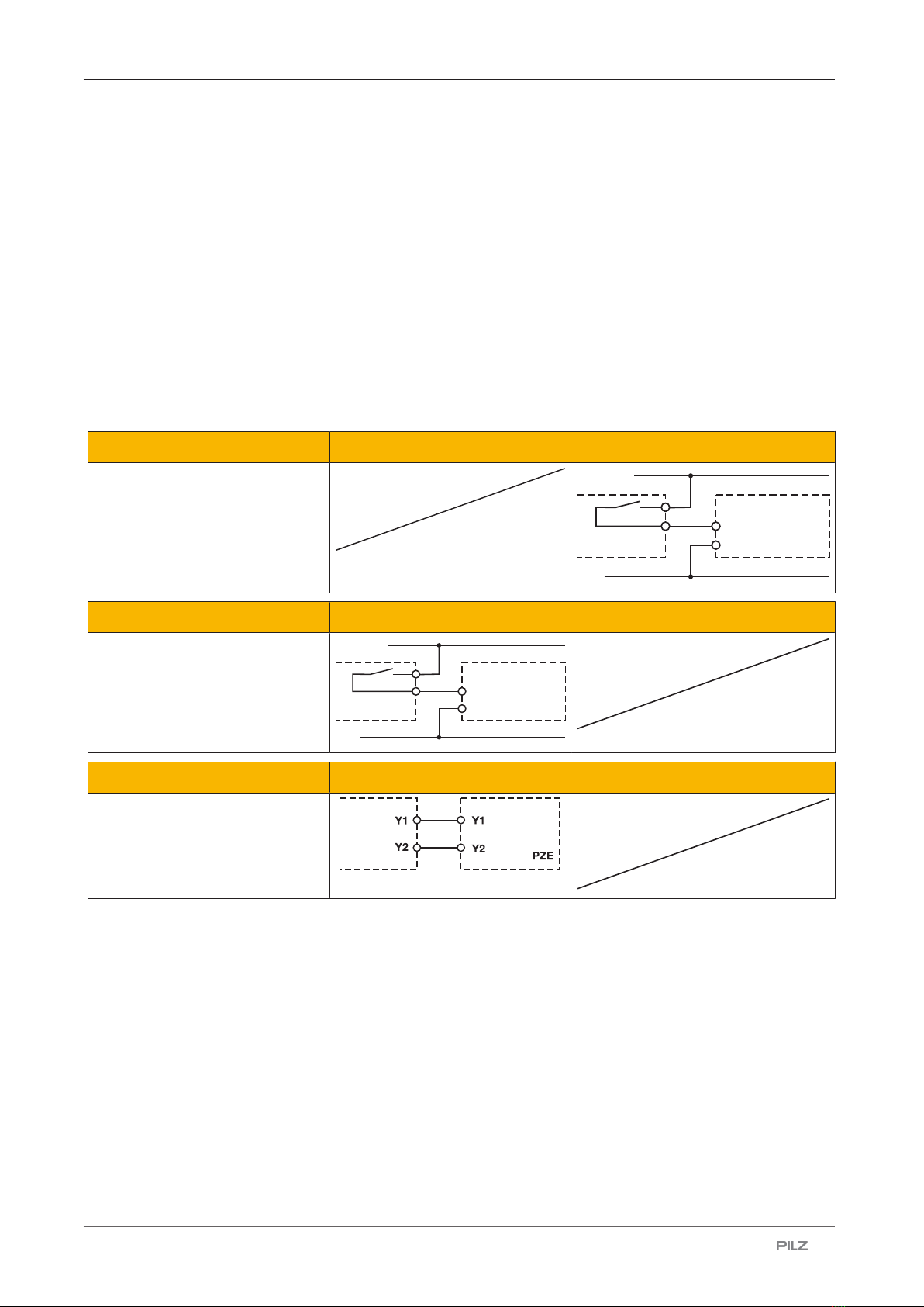
Preparing for operation
Supply voltage AC DC
A1
A2 PZE
24 V DC
0 V
Input circuit Single-channel Dual-channel
Base unit:
Safety relay PNOZX
Driven via safety contacts
A1
A2 PZE
24 V DC
0 V
Feedback loop Base unit: Safety relay PNOZ X
Y1 and Y2 are inputs on the base
unit; they evaluate the feedback
loop
PZE X4V8
Operating Manual PZE X4V8
1003204-EN-11 | 10
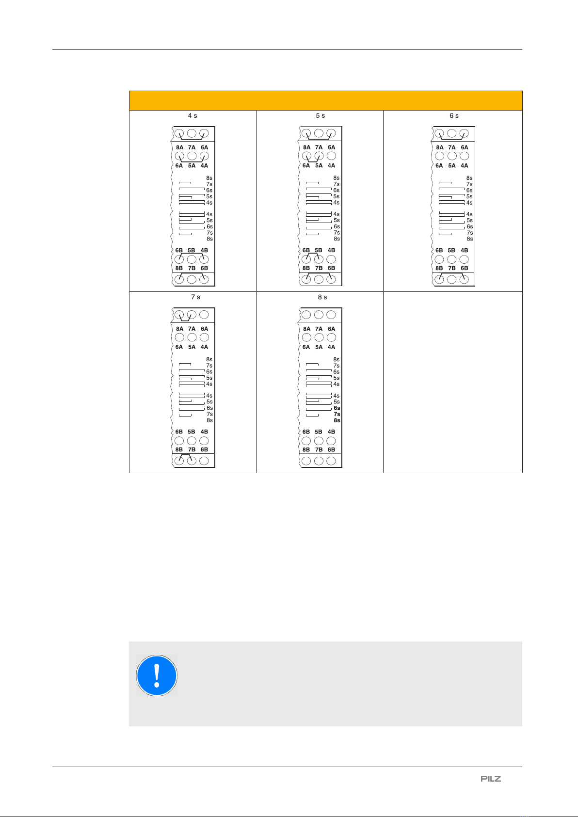
Setting the delay time
Operation
When the relay outputs are switched on, the mechanical contact on the relay cannot be
tested automatically. Depending on the operational environment, measures to detect the
non-opening of switching elements may be required under some circumstances.
When the product is used in accordance with the European Machinery Directive, a check
must be carried out to ensure that the safety contacts on the relay outputs open correctly.
Open the safety contacts of the contact expansion module (switch off outputs of the base
unit) and start the base unit again so that the internal diagnostics can check that the safety
contacts open correctly
}for SIL CL 2/PL d at least 1x per year
NOTICE
The safety functions should be checked after initial commissioning and each
time the plant/machine is changed. The safety functions may only be
checked by qualified personnel.
This manual suits for next models
1
Table of contents
Other Pilz Relay manuals


Pilz
Pilz PNOZ s4.1 User manual

Pilz
Pilz PNOZ X1 User manual

Pilz
Pilz PNOZ X2.3P User manual

Pilz
Pilz PNOZ e3.1p User manual

Pilz
Pilz S1IM/UP User manual

Pilz
Pilz PNOZ XV2P User manual

Pilz
Pilz PNOZ 2 22151-3FR-03 User manual

Pilz
Pilz PNOZ e3.1p User manual

Pilz
Pilz P2HZ X4P User manual

Pilz
Pilz S1UK User manual


