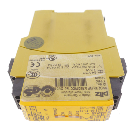
Pilz PNOZ msi b4 Box User manual

PNOZ msi b4 Box
Operating Manual 1003058-EN-03
}Accessories PNOZmulti

Preface
This document is a translation of the original document.
All rights to this documentation are reserved by Pilz GmbH & Co. KG. Copies may be made
for internal purposes. Suggestions and comments for improving this documentation will be
gratefully received.
Source code from third-party manufacturers or open source software has been used for
some components. The relevant licence information is available on the Internet on the Pilz
homepage.
Pilz®, PIT®, PMI®, PNOZ®, Primo®, PSEN®, PSS®, PVIS®, SafetyBUS p®,
SafetyEYE®, SafetyNET p®, the spirit of safety® are registered and protected trademarks
of Pilz GmbH & Co. KG in some countries.
SD means Secure Digital

PNOZ msi b4 Box
Operating Manual PNOZ msi b4 Box
1003058-EN-03 3
Introduction
Validity of documentation
This documentation is valid for the product PNOZ msi b4 Box from Version 2.0 .
This operating manual explains the function and operation, describes the installation and
provides guidelines on how to connect the product.
Description
The shielded junction box PNOZ msi b4 Box is used to connect
}An incremental encoder with an additional feed for the incremental encoder supply
or
}An incremental encoder in conjunction with a proximity switch with/without pull resistor
(dual encoder evaluation) with an additional supply for the proximity switch
or
}2 proximity switches with/without pull resistor with an additional supply for the proximity
switches
to the Pilz speed monitors.
Front view

PNOZ msi b4 Box
Operating Manual PNOZ msi b4 Box
1003058-EN-03 4
Installation
}The junction box should be installed in a control cabinet with a protection type of at
least IP54.
}Fit the junction box to a horizontal mounting rail.
}Use the locking slide on the rear of the junction box to attach it to a mounting rail.
}In environments exposed to heavy vibration, the unit should be secured using a fixing
element (e.g. retaining bracket or end angle).
}Open the locking slide before lifting the unit from the mounting rail.
Mounting distances
For the wiring to be EMC-compliant, the junction box must maintain a distance of at least
5.5 mm from other conductive parts (e.g. adjacent housing parts) (see diagram).
5,5 mm
(0.22“)
5,5 mm
(0.22“)
5,5 mm
(0.22“)
5,5 mm
(0.22“)
conductive parts
conductive parts

PNOZ msi b4 Box
Operating Manual PNOZ msi b4 Box
1003058-EN-03 5
Dimensions in mm
131,3 (5.17“)
100 (3.94“)
25 (0.98“)
103,18 (4.06“)
Connection
INFORMATION
The connected supply voltages and the sensors have to be supplied from
power supplies that comply with the regulations for extra low voltages with
safe electrical isolation.
Shielded line
Acorn nut
Sealing ring
Connecting piece
Braided shield
Lamellar insert
1. Remove the external insulation of the line and expose the braided shield, depending on
the conductor cross section, to approx. 10-15 mm.
2. Push acorn nut and lamellar insert with gasket onto the line.
3. Bend braided shield to the outside at a right angle (90°).
4. Crimp over braided shield towards the external cable insulation, i.e. crimp it over again
by 180°.
5. Insert connecting piece up to the braided shield and turn it shortly back and forth round
the line axis.
6. Push lamellar insert with gasket into the connecting piece and snap in the anti-twist pro-
tection.
7. Screw the acorn nut firmly.

PNOZ msi b4 Box
Operating Manual PNOZ msi b4 Box
1003058-EN-03 6
Internal view
The cable ducts and the corresponding terminals are each labelled identically (X1 ... X4).
}Cable ducts at X1 and X4:
Size M12x1.5 with terminals for cable diameters from 3 to 6.5 mm, tighten with spanner
size SW 14 mm and torque setting 8 Nm.
}Cable ducts at X2 and X3:
Size M16x1.5 with terminals for cable diameters from 5 to 9 mm, tighten with spanner
size SW 17 mm and torque setting 8 Nm.
The identically named signals (GND, S, 24 V...) are connected to each other between the
terminals X1 ... X4 internally.
INFORMATION
When using crimp connectors the connection wires can be inserted into the
connectors of the spring-loaded terminals. Pressing the operating pushbut-
ton is necessary only to undo the connection.

PNOZ msi b4 Box
Operating Manual PNOZ msi b4 Box
1003058-EN-03 7
Internal wiring diagram
X1
AnA B nB ZnZ S24 V GND
X2
X3
X4
AnA B nB ZnZ S 24 V GND
GND
S
A
nA
B
nB
Z
nZ
24 V
GND
S
A
nA
B
nB
Z
nZ
24 V
24 V
GND
S
A
nA
B
nB
Z
GND
24 V
GND
S
24 V
24 V
B
24 V
Z
GND

PNOZ msi b4 Box
Operating Manual PNOZ msi b4 Box
1003058-EN-03 8
Connection examples
Example 1
Encoder directly to a speed monitor from Pilz, supply voltage for encoder via bridge at ter-
minals S - 24 V of connector X4,
Option: Wiring of encoder outputs (connector X3)
X1
GND
S
A
nA
B
nB
Z
nZ
GND
S
A
nA
B
nB
Z
nZ
X2
GND
S
A
nA
B
nB
Z
nZ
GND
S
A
nA
B
nB
Z
nZ
X4
GND
S
24 V
24 V
B
24 V
Z
GND
0 V
24 V
24 V
24 V
X3
GND
S
A
nA
B
nB
Z
GND
24 V
24 V
Encoder
Speed monitor
from Pilz

PNOZ msi b4 Box
Operating Manual PNOZ msi b4 Box
1003058-EN-03 9
Example 2
Encoder and proximity switch (sensor type in PNOZmulti Config: HTL differential + Z fre-
quency Ini pnp) for monitoring for broken shearpins, do not connect Z and nZ of the en-
coder, supply voltage for encoder via bridge at terminals S - 24 V of connector X4,
Option: Wiring of the outputs of the encoder (connector X3) and pull-down resistor for Z
(connector X4)
X1
GND
S
A
nA
B
nB
Z
nZ
GND
S
A
nA
B
nB
Z
nZ
X2
GND
S
A
nA
B
nB
Z
nZ
GND
S
A
nA
B
nB
Z
nZ
X4
GND
S
24 V
24 V
B
24 V
Z
GND
0 V
24 V
24 V
24 V
X3
GND
S
A
nA
B
nB
Z
GND
24 V
24 V
0 V
24 V
Encoder
Output
Proximity switch pnp
Speed monitor
from Pilz

PNOZ msi b4 Box
Operating Manual PNOZ msi b4 Box
1003058-EN-03 10
Example 3
2 proximity switches, supply voltage for proximity switches via connector X4
Option: Pull-down/pull-up resistance for A (connector X2), pull-down/pull-up resistance for
B (connector X4), monitoring track S (connector X4)
X1
GND
S
A
nA
B
nB
Z
nZ
GND
S
A
nA
B
nB
Z
nZ
X2
GND
S
A
nA
B
nB
Z
nZ
X4
GND
S
24 V
24 V
B
24 V
Z
GND
0 V
24 V
24 V
24 V
X3
GND
S
A
nA
B
nB
Z
GND
24 V
24 V
0 V
24 V
24 V
0 V
Output
Proximity switch pnp/
npn
Proximity switch pnp/
npn
Output
Speed monitor
from Pilz

PNOZ msi b4 Box
Operating Manual PNOZ msi b4 Box
1003058-EN-03 11
Example 4
Tap the signals of the encoder via a Pilz adapter (e.g. MM A MINI-IO CAB99) and the prox-
imity switch (sensor type in PNOZmulti Config: HTL differential + Z frequency Ini pnp), sup-
ply voltage for proximity switch (connector X4)
Option: Pull-down resistor for Z (connector X4)
X1
GND
S
A
nA
B
nB
Z
nZ
GND
S
A
nA
B
nB
Z
nZ
X2
GND
S
A
nA
B
nB
Z
nZ
GND
A
nA
B
nB
X4
GND
S
24 V
24 V
B
24 V
Z
GND
0 V
24 V
24 V
24 V
X3
GND
S
A
nA
B
nB
Z
GND
24 V
24 V
0 V
24 V
Adapter
Output
Proximity switch pnp
Speed monitor
from Pilz

PNOZ msi b4 Box
Operating Manual PNOZ msi b4 Box
1003058-EN-03 12
Example 5
Encoder and proximity switch (sensor type in PNOZmulti Config: HTL differential + Z fre-
quency Ini pnp) for monitoring for broken shearpins, do not connect and/or separate Z and
nZ of the encoder, separate supply voltage for proximity switch (via connector X3) and en-
coder,
Option: Pull-down resistor for Z (connector X4)
X1
GND
S
A
nA
B
nB
Z
nZ
GND
S
A
nA
B
nB
Z
nZ
X2
GND
S
A
nA
B
nB
Z
nZ
X4
GND
S
24 V
24 V
B
24 V
Z
GND
0 V
5-24 V
24 V
24 V
X3
GND
S
A
nA
B
nB
Z
GND
24 V
24 V
0 V
24 V
24 V
0 V
GND
S
A
nA
B
nB
Z
nZ
Output Proximity switch pnp
Supply voltage proximity
switch
Encoder
Speed monitor
from Pilz

PNOZ msi b4 Box
Operating Manual PNOZ msi b4 Box
1003058-EN-03 13
Example 6
as in example 4, PNOZ msi b4 box replaces adapter, proximity switch with own supply
voltage,
Option: Pull-down resistor for Z (connector X3)
X1
GND
S
A
nA
B
nB
Z
nZ
GND
S
A
nA
B
nB
Z
nZ
X2
GND
S
A
nA
B
nB
Z
nZ
X4
GND
S
24 V
24 V
B
24 V
Z
GND
0 V
24 V
24 V
24 V
X3
GND
S
A
nA
B
nB
Z
GND
24 V
24 V
GND
S
A
nA
B
nB
Z
nZ
GND
A
nA
B
nB
24 V
0 V
Proximity switch pnp
Drive controller
Output
Encoder
24 V infeed
Speed monitor
from Pilz

PNOZ msi b4 Box
Operating Manual PNOZ msi b4 Box
1003058-EN-03 14
INFORMATION
Further information on the connection is available in the operating instruc-
tions for the respective speed monitor.
INFORMATION
The GND signal is not connected to earth.

PNOZ msi b4 Box
Operating Manual PNOZ msi b4 Box
1003058-EN-03 15
EMC-compliant wiring
INFORMATION
With EMC-compliant wiring inside the connection box, make sure that the
cores for signals A, nA or B, nB or Z, nZ
– Are no longer than necessary
– Remain twisted in pair as far as the terminal.
The individual core strands must not touch the housing wall.
EMC-compliant wiring for connecting an encoder and a drive:
Encoder
PNOZ msi B4 Box
and
MM A MINI-IO CABxx
PNOZ m EF
1MM
X12
PNOZ m Bx
A1 A2
Drive
GND
DIN-Rail
C
Power Supply
SELV
PNOZ multi 2
L1 N PE
A
E
Power Supply
from Drive
Cabinet
To avoid EMC interference we recommend that the shield on the sensor cable is connected
to earth at C orE. Depending on the application, the connection to the functional earth may
also be at a different location (here A).

PNOZ msi b4 Box
Operating Manual PNOZ msi b4 Box
1003058-EN-03 16
EMC-compliant wiring for connecting an encoder and a proximity switch:
EncoderINI_Z
PNOZ msi B4 Box
and
MM A MINI-IO CABxx
PNOZ m EF
1MM
X12
PNOZ m Bx
Power Supply
SELV
PNOZ multi 2
A1 A2
L1 N PE
A
DIN-Rail
C
Power Supply
SELV
Encoder / INI
L1 N PE
B
GND24V / S
E
Cabinet
To avoid EMC interference we recommend that the shield on the sensor cable is connected
to earth at C orE. Depending on the application, the connection to the functional earth may
also be at a different location (here A or B).

PNOZ msi b4 Box
Operating Manual PNOZ msi b4 Box
1003058-EN-03 17
Technical details
General
Approvals cULus Listed
Electrical data
Operating voltage 30 V
Environmental data
Ambient temperature
Temperature range 0 - 60 °C
Storage temperature
Temperature range -25 - 70 °C
Condensation during operation Not permitted
Rated insulation voltage 30 V
Protection type
In accordance with the standard EN 60529
Mounting area (e.g. control cabinet) IP54
Housing IP20
Terminals IP20
Mechanical data
Material
Housing Hot dip galvanised steel
Connection type Spring-loaded terminal
Mounting type Fixed
Conductor cross section with spring-loaded terminals:
Flexible with/without crimp connector 0,08 - 1,5 mm², 28 - 16 AWG
Stripping length with spring-loaded terminals 9 mm
Dimensions
Height 103,1 mm
Width 25 mm
Depth 131,3 mm
Weight 280 g

PNOZ msi b4 Box
Operating Manual PNOZ msi b4 Box
1003058-EN-03 18
Order reference
Product
Product type Features Order No.
PNOZ msi b4 Box Junction box 773845
Accessories
Product type Features Order No.
PNOZ msi9p Connection cable, 5.00 m 773 856
PNOZ msi10p Connection cable, 2.50 m 773 854
PNOZ msi11p Connection cable, 1.50 m 773 855
MM A MINI-IO CAB99 Connection cable, 1.50 m 772 200
MM A MINI-IO CAB99 Connection cable, 2.50 m 772 201
MM A MINI-IO CAB99 Connection cable, 5.00 m 772 202

The Best of
German
Engineering
Partner of:
Support
Technical support is available from Pilz round the clock.
Americas
Brazil
+55 11 97569-2804
Canada
+1 888-315-PILZ (315-7459)
Mexico
+52 55 5572 1300
USA (toll-free)
+1 877-PILZUSA (745-9872)
Asia
China
+86 21 60880878-216
Japan
+81 45 471-2281
South Korea
+82 31 450 0680
Australia
+61 3 95446300
Europe
Austria
+43 1 7986263-0
Belgium, Luxembourg
+32 9 3217575
France
+33 3 88104000
Germany
+49 711 3409-444
Ireland
+353 21 4804983
Italy
+39 0362 1826711
Scandinavia
+45 74436332
Spain
+34 938497433
Switzerland
+41 62 88979-30
The Netherlands
+31 347 320477
Turkey
+90 216 5775552
United Kingdom
+44 1536 462203
You can reach our
international hotline on:
+49 711 3409-444
CMSE®, InduraNET p®, PAS4000®, PAScal®, PASconfig®, Pilz®, PIT®, PLID®, PMCprimo®, PMCprotego®, PMCtendo®, PMD®, PMI®, PNOZ®, Primo®, PSEN®, PSS®, PVIS®, SafetyBUS p®,
SafetyEYE®, SafetyNET p®, THE SPIRIT OF SAFETY®are registered and protected trademarks of Pilz GmbH & Co. KG in some countries. We would point out that product features may vary
from the details stated in this document, depending on the status at the time of publication and the scope of the equipment. We accept no responsibility for the validity, accuracy
and entirety of the text and graphics presented in this information. Please contact our Technical Support if you have any questions.
Pilz develops environmentally-friendly products using
ecological materials and energy-saving technologies.
Oces and production facilities are ecologically designed,
environmentally-aware and energy-saving. So Pilz oers
sustainability, plus the security of using energy-ecient
products and environmentally-friendly solutions.
Pilz GmbH & Co. KG
Felix-Wankel-Straße 2
73760 Ostfildern, Germany
Tel.: +49 711 3409-0
Fax: +49 711 3409-133
www.pilz.com
100XXXX-DE-0X
0-0-1-3-000, 2015-00 Printed in Germany
© Pilz GmbH & Co. KG, 2015
1003058-EN-03, 2016-06 Printed in Germany
© Pilz GmbH & Co. KG, 2015
Front cover
Table of contents
Other Pilz Relay manuals