Pilz PSS Series User manual

-~
ARTISAN
®
~I
TECHNOLOGY
GROUP
Your definitive source
for
quality
pre-owned
equipment.
Artisan Technology
Group
Full-service,
independent
repair
center
with
experienced
engineers
and
technicians
on staff.
We
buy
your
excess,
underutilized,
and
idle
equipment
along
with
credit
for
buybacks
and
trade-ins
.
Custom
engineering
so
your
equipment
works
exactly as
you
specify.
•
Critical
and
expedited
services
•
Leasing
/
Rentals/
Demos
• In
stock/
Ready-to-ship
•
!TAR-certified
secure
asset
solutions
Expert
team
ITrust
guarantee
I
100%
satisfaction
All
tr
ademarks,
br
a
nd
names, a
nd
br
a
nd
s a
pp
earing here
in
are
th
e property of
th
e
ir
r
es
pecti
ve
ow
ner
s.
Find the Pilz PSS 3056-1 at our website: Click HERE

The spirit of safety.
Programmable Safety Systems
PSS-Range
PSS 3056 Series
Installation Manual
Item No. 19 025
Artisan Scientific - Quality Instrumentation ... Guaranteed | (888) 88-SOURCE | www.artisan-scientific.com

All rights to this manual are reserved by Pilz GmbH & Co. KG. Copies may be made for
internal purposes.
In the interests of continual technical advancement we reserve the right to amend
specifications without prior notice. No responsibility accepted for errors or omissions.
The names of products, goods and technologies used in this manual are trademarks of the
companies concerned.
VII, 01/00
Artisan Scientific - Quality Instrumentation ... Guaranteed | (888) 88-SOURCE | www.artisan-scientific.com

1Installation Manual: PSS 3056 Series
Introduction 1-1
Definition of symbols 1-1
Safety Regulations 2-1
Supplying power to the PSS 2-1
Supplying the I/Os 2-3
Installation 2-4
Connections 2-5
Electromagnetic Compatibility (EMC) 3-1
Overview 3-1
Making the installation EMC-compatible 3-2
Connecting the earth cables 3-2
Cabling 3-3
Equipotential bonding 3-4
Screened cables 3-4
Suppression of inductive loads 3-5
Insulation voltage test 3-5
Miscellaneous 3-6
Installing within an enclosure or wall-mounting 3-6
Testing the EMC-compatibility of an installation 3-7
Installation 4-1
Installing the system 4-1
Installing the system in a control cabinet 4-2
Contents
Artisan Scientific - Quality Instrumentation ... Guaranteed | (888) 88-SOURCE | www.artisan-scientific.com

Contents
2Installation Manual: PSS 3056 Series
Connecting the Inputs and Outputs 5-1
Configuration of the screw terminals and connector
description 5-1
Notes on wiring 5-5
On-board digital inputs 5-6
Configuration of the standard PSS 3056 5-7
Example: Single-channel, failsafe input device, unchecked 5-8
Example: Dual-channel input devices, unchecked 5-10
Example: Single-channel, failsafe input device, with test pulse 5-12
Example: Dual-channel, failsafe input device, with test pulse 5-14
On-board single-pole 2 A outputs/test pulses 5-16
Configuration of the standard PSS 3056 5-17
On-board dual-pole 2 A outputs 5-18
Configuration of the standard PSS 3056 5-19
Interfaces 6-1
PG programming interface 6-1
RS 232 user interface 6-1
PSS SB 3056: SafetyBUS p interface 6-2
Appendix 7-1
Changes to the Installation Manual 7-1
Artisan Scientific - Quality Instrumentation ... Guaranteed | (888) 88-SOURCE | www.artisan-scientific.com

Installation Manual: PSS 3056 Series 1-1
This installation manual contains all the information you need to install a
PSS system from the PSS 3056 series. It gives safety guidelines which
should be followed during installation and also describes the installation
procedure and measures which can be taken to ensure EMC compliance.
Examples are also given to show how the on-board inputs and outputs
should be connected.
This installation manual is valid for the standard PSS 3056, as well as the
PSS 3056-1, PSS 3056-2 and PSS SB 3056. If you are using the PSS SB
3056 you should also refer to the “SafetyBUS p Installation Manual”.
As the individual units differ only in the number and configuration of the
different on-board I/Os and available interfaces, examples shown relate to
the standard PSS 3056 unit. They can be used on all versions of the PSS
3056, unless stated otherwise.
Throughout this manual, the term “safety system” or simply “PSS” will be
used to refer to programmable safety systems in the PSS 3056 series.
Definition of symbols
Information in this manual which is of particular importance can be
identified as follows:
DANGER!
This warning must be heeded! It warns of a hazardous situation which
poses an immediate threat of serious injury and death, and indicates
preventive measures which can be taken.
WARNING!
This warning must be heeded! It warns of a hazardous situation which
could lead to serious injury and death, and indicates preventive
measures which can be taken.
Introduction
Artisan Scientific - Quality Instrumentation ... Guaranteed | (888) 88-SOURCE | www.artisan-scientific.com

Introduction
1-2 Installation Manual: PSS 3056 Series
CAUTION!
This refers to a hazard which can lead to a less serious or minor injury
plus material damage, and also provides information on preventive
measures which can be taken.
NOTICE
This describes a situation in which the unit(s) could be damaged and also
provides information on preventive measures which can be taken.
INFORMATION
This gives advice on applications and provides information on special
features, as well as highlighting areas within the text which are of
particular importance.
Artisan Scientific - Quality Instrumentation ... Guaranteed | (888) 88-SOURCE | www.artisan-scientific.com

Installation Manual: PSS 3056 Series 2-1
To ensure that the safety system functions correctly, please follow the
safety guidelines given below:
• Electrical connections should be made by a qualified electrical engineer
who is familiar with the information in this manual as well as the relevant
regulations concerning health and safety at work.
• Ensure VDE and local regulations are met, especially those relating to
safety. The relevant safety regulations for the respective application
must also be met.
• CAUTION!
Electrostatic discharge can damage components on the PSS. Ensure
against discharge before touching the terminal strips, e.g. by touching an
earthed, conductive surface or by wearing an earthed armband.
• Ensure all the requirements of the relevant trade associations are met.
• Ensure the wiring instructions in Chapter 5 are followed.
• The internal power supply on the safety system must not be connected
to any other devices.
• If the system is altered in any way, such as exchanging a component or
carrying out soldering work, the guarantee, and any approval, will be
rendered invalid.
• The date of manufacture can be found on the test label.
Supplying power to the PSS
• The safety system requires a 24 VDC supply.
Check that the voltage supplied from the external power supply
corresponds.
•CAUTION!
The tolerance on the supply voltage for the system's power supply is
+10 % or -15 % maximum. Safe operation cannot be guaranteed outside
this range.
• Overvoltage and spikes of interference can damage the PSS power
supply. If this occurs the unit will switch to a safe condition. Please refer
to the relevant EMC-measures described in Chapter 3.
Safety Regulations
Artisan Scientific - Quality Instrumentation ... Guaranteed | (888) 88-SOURCE | www.artisan-scientific.com

Safety Regulations
2-2 Installation Manual: PSS 3056 Series
~
=
PSS 3056 series
L1
N
+24 V
0 V
External power supply
24 V
0 V Functional earth
Optional:
Connect to the
0 V mains and
earth at a single
point
Connect in star to the central
earth bar
• To achieve the lowest possible residual ripple (< ± 1.2 V), we
recommend that you install a three-phase bridge rectifier or regulated
supply.
• The external 24 V power supply must be capable of supplying a
minimum of 8 A for approximately 1 s.
• The fuse between the external and the PSS power supply protects the
cabling. The size of the fuse will depend on the cable cross section and
on local regulations.
•WARNING!
Safe electrical isolation must be ensured for the external 24 V supply.
Failure to do so could result in electric shock. Power supplies must
conform to DIN VDE 0551 / EN 60 742 and DIN VDE 0160.
•
The external 24 V supply
should be connected to the PSS power supply
as shown in the diagram below. The external supply should be earthed
in accordance with local regulations.
If the external supply is also being used to supply the I/Os, the 0 V output
should be earthed as shown in the section entitled “Supplying the input/
outputs”.
Fig. 2-1: Supplying the system
Artisan Scientific - Quality Instrumentation ... Guaranteed | (888) 88-SOURCE | www.artisan-scientific.com

Installation Manual: PSS 3056 Series 2-3
Supplying the I/Os
• The digital inputs and outputs require a 24 V supply (see connection
diagrams in Chapter 5). Check that the voltage supplied from the
external power supply corresponds
• We recommend that the PSS and the I/Os are fed through two separate
power supplies. This will mean that any breaks in the supply to the I/Os
can be kept away from the CPU.
• The external 24 V power supply must be capable of supplying a
maximum current which is calculated from the sum of all the inputs
multiplied by 10 mA, plus the total current from the maximum number of
outputs that can be driven simultaneously.
•CAUTION!
The tolerance on the supply voltage for the PSS power supply is + 20 %
or -15 % maximum. Safe operation cannot be guaranteed outside this
range.
• To achieve the lowest possible residual ripple (< ± 1.2 V), we
recommend that you install a three-phase bridge rectifier or regulated
supply.
• The fuse between the external power supply and the supply terminals on
the outputs protects the cabling. The size of the fuse will depend on the
cable cross section and on local regulations.
•WARNING!
Safe electrical isolation must be ensured for the external 24 V supply.
Failure to do so could result in electric shock. Power supplies must
conform to DIN VDE 0551 / EN 60 742 and DIN VDE 0160.
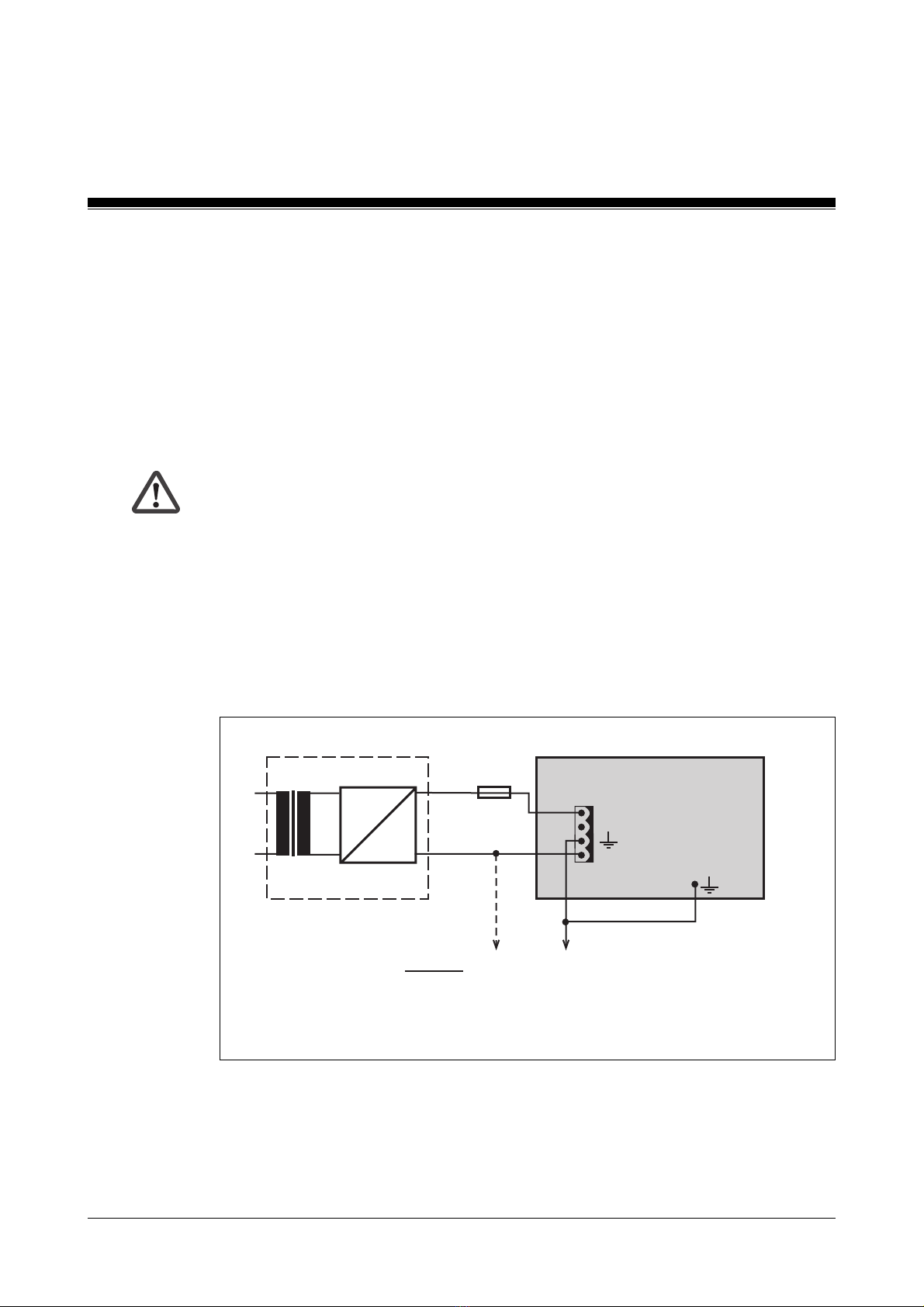
• The external power supply should be connected to the supply terminals
on the I/Os as shown overleaf.
There must be no direct connection between “N” and the 0 V output on
the external power supply.
The 0 V connections on all the 24 V power supplies should be connected
and the 0 V mains earthed at a single point. The connection of the 0 V
supply to the central earth bar or earth fault monitor must be in
accordance with the relevant national regulations (such as EN 60 204,
VDE 0113, NFPA 79-1991:17-7, NEC: Article 250, for example).
Artisan Scientific - Quality Instrumentation ... Guaranteed | (888) 88-SOURCE | www.artisan-scientific.com

Safety Regulations
2-4 Installation Manual: PSS 3056 Series
~
=
PSS 3056 series
L1
N
+24 V
0 V
External power supply
24 V
0 V Functional earth
Connect in star to the central
earth point
Connect to the 0 V mains
and earth at a single point
Supply terminals
on the inputs/outputs
Installation
• The system should be installed in an enclosure (e.g. control cabinet)
which conforms to the protection class required.
• When installing the unit in an enclosure such as a control cabinet, the
technical specifications below must be taken into account:
Protection type (EN 60 529, 10/91) IP 20
Protection class (DIN VDE 0106,
Part 1/A1, 04/90) 1
Mounting position Vertical
Ambient temperature (DIN IEC 68-2-14, 06/87) 0 ... 60 °C
Storage temperature (EN 60 068-2-1/-2, 03/93) -25 ... +70 °C
Relative humidity
(DIN IEC 68-2-30, 09/86) Max. 95 % r.h.
Condensation Not permitted
Vibration (EN 60 068-2-6, 04/95) Frequency range:
10 ... 100 Hz
Amplitude:
0.1 mm, max. 5g
Shock (DIN IEC 68-2-29) 30g, 11 ms/10g, 16 ms
EMC EN 50 082-2, 03/95
EN 55 011 A, 08/96
Fig. 2-2: Connecting the power supply to the I/Os
Artisan Scientific - Quality Instrumentation ... Guaranteed | (888) 88-SOURCE | www.artisan-scientific.com

Installation Manual: PSS 3056 Series 2-5
• Ensure there is sufficient ventilation to prevent heat building up within the
control cabinet.
• In extreme ambient conditions, additional measures may be required in
order to keep within the prescribed value range (e.g. air-conditioning
within the control cabinet).
• The safety system must be installed in such a way that buttons and
switches cannot be operated unintentionally.
Connections
• Cable layout must meet the EMC-guidelines stated in Chapter 3.
• Each supply terminal should have its own power supply cable as shown
in the connection diagrams (do not make through-connections).
• All supply terminals must be supplied with the voltages they require,
otherwise it will not be possible to carry out the module test (error
message will be generated).
• The current at each slot connector should be 10 A maximum.
• Screened cables are not required for digital I/Os.
• Minimum ranges for cable cross sections on field connection terminals
in mm2, in accordance with EN 61 131-2, 08/94:
- Digital inputs: 0.5 (AWG20) ... 1.5 (AWG16)
- Digital outputs: 0.5 (AWG20) ... 2.0 (AWG14)
- Power supply: 1.5 (AWG16) ... 2.5 (AWG12)
- Earth: 1.5 (AWG16) ... 2.5 (AWG12)
• Use copper wiring.
• The torque setting on the connection terminals should be 0.5 ... 0.6 Nm.
Artisan Scientific - Quality Instrumentation ... Guaranteed | (888) 88-SOURCE | www.artisan-scientific.com

Safety Regulations
2-6 Installation Manual: PSS 3056 Series
Notes
Artisan Scientific - Quality Instrumentation ... Guaranteed | (888) 88-SOURCE | www.artisan-scientific.com

Installation Manual: PSS 3056 Series 3-1
Overview
The safety system is designed to be installed within an electromagnetic
industrial environment. To ensure electromagnetic compatibility the
correct procedures must be carried out when installing the system.
A device is electromagnetically compatible if:
• It functions without error in a given electromagnetic environment.
• It does not adversely affect its own environment.
Electromagnetic interference reaches the system through:
• Radiated fields
• Power supply
• Earth cabling
• Bus
• Interfaces
• Input and output cables
The interference can be transferred from the source to the receiver
(interference sink) via the coupling routes.
Interference reaches the interference sink (e.g. the PSS 3056) in various
ways:
• DC coupling
This occurs if the source and sink of interference have common cable
connections. The common cable presents complex resistances, inducing
potential differences. Possible sources of interference are switches/
relays, running motors or varying potentials for other systems on the
same power supply.
Fig. 3-1: Electromagnetic interference
Electromagnetic Compatibility (EMC)
Coupling Interference
sink
Source of
interference
Artisan Scientific - Quality Instrumentation ... Guaranteed | (888) 88-SOURCE | www.artisan-scientific.com

Electromagnetic Compatibility (EMC)
3-2 Installation Manual: PSS 3056 Series
• Capacitive (electrical) coupling
A different potential between the source and interference sink (e.g. two
cables) creates an electrical field. Cross-coupling is proportional to the
rate of voltage change.
Possible sources of interference are contactors, static discharge, parallel
signal cables.
• Inductive (magnetic) coupling
A live cable produces a magnetic field which surrounds both the live and
neighbouring cables. Interference voltage is induced. Cross-coupling is
proportional to the rate of current change.
Possible sources of interference are mains cables running in parallel, live
cables, high frequency cables, inductors, transformers, motors.
• Electromagnetic coupling
A cable can emit a signal as a radio wave. This wave is then picked up
by another cable.
Possible sources of interference are transmitters such as radios, sparks
from spark plugs, welding equipment etc.
NOTICE
Stronger HF transmitters should only be operated at a distance of more
than 0.6 m.
• Static discharge
Static discharge occurs where there are very high differences in potential
between two points. If the two points are brought closer together or if the
potential difference is increased, discharges can occur in the air gaps.
Possible sources of interference are people who are statically charged
from a synthetic carpet, for example.
Making the installation EMC-compatible
Connecting the earth cables
PSS safety systems all meet protection class 1 (DIN VDE 0106, Part 1/A1,
04/90). The prescribed earth points are designed for your safety and to
guarantee compliance with noise resistance requirements.
Artisan Scientific - Quality Instrumentation ... Guaranteed | (888) 88-SOURCE | www.artisan-scientific.com

Installation Manual: PSS 3056 Series 3-3
• The housing should be connected to the earth conductor “PE”. A cable
cross section of at least 2.5 mm2should be used. Connections should
be kept as short as possible.
• Always connect the earth conductor “PE” to the central earth point in star
form.
• The 0 V connections on all the 24 V power supplies should be connected
and the 0 V mains earthed at a single point. The connection of the 0 V
supply to the central earth bar or earth fault monitor must be in
accordance with the relevant national regulations (such as EN 60 204,
VDE 0113, NFPA 79-1991:17-7, NEC: Article 250, for example).
• Connections should be protected from corrosion.
• Flexible earthing straps should be used on moving earth parts (e.g.
machine parts, gates). Ensure these earthing straps are as short and
wide as possible.
Cabling
It is possible to differentiate between cables according to their function.
The following groups exist:
• Group 1: Data and supply lines for DC voltages below 60 V and AC
voltages below 25 V
• Group 2: Data and supply lines for DC voltages from 60 V to 400 V and
AC voltages from 25 V to 400 V
• Group 3: Supply lines above 400 V
Cabling inside buildings:
• The cable groups listed above should be laid separately.
• Cables of the same group can be laid within the same cable duct.
• Lines from group 1 and group 2 should be laid in separate groups or in
cable ducts which are at least 10 cm apart.
• Lines from group 1 and group 3 should be laid in separate groups or in
cable ducts which are at least 50 cm apart.
Artisan Scientific - Quality Instrumentation ... Guaranteed | (888) 88-SOURCE | www.artisan-scientific.com

Electromagnetic Compatibility (EMC)
3-4 Installation Manual: PSS 3056 Series
• Data and signal lines should be laid as close as possible to an earthed
surface.
Cabling to open air systems:
• As far as possible use metal conduits. These should be electrically
connected and earthed.
• Ensure there is sufficient protection against lightning by:
- Using metal conduits earthed at both ends, or concrete cable ducts with
reinforcements connected across the joints.
Equipotential bonding
Potential differences can occur through potential connected couplings
between the safety system and peripheral devices or cable shields, which
are connected at either end and have different earth connections. In order
to avoid interference, equipotential bonding cables must be installed. In
doing so, you must ensure the following:
• Select a low impedance equipotential bonding cable.
• If the safety system and peripheral devices are connected with screened
signal cables which are earthed at either end, the impedance is
calculated as follows:
Impedance equipotential bonding cable = 10% of screen impedance.
• Select the following as standard values for the cross section of the
equipotential bonding cable:
16 mm2for equipotential bonding cables up to 200 m in length.
25 mm2for equipotential bonding cables over 200 m in length.
• Use copper or galvanised steel equipotential bonding cable.
• Connect equipotential bonding cables to the earth conductor over as
wide a surface area as possible.
• As short a distance as possible should be kept between the equipotential
bonding cable and signal cable.
Artisan Scientific - Quality Instrumentation ... Guaranteed | (888) 88-SOURCE | www.artisan-scientific.com

Installation Manual: PSS 3056 Series 3-5
Screened cables
Interference currents arising from electrical, magnetic or electromagnetic
fields of interference must be diverted to cable screens via the earth bars
connected to the enclosure. Please remember the following:
• Connect the screens with low impedence to the earth conductor.
• Use cables with braided screening, with a minimum cover area of 80%.
• For high frequency areas connect the screen at both ends.
• For low frequency areas connect the screen at one end; this is also valid
when laying cables without equipotential bonding or using foil screens.
• Use metal or metallised plugs to connect cables for serial data transfer.
• The screen must have no connection to the connector housing if it is not
located at the end of the cable.
• At the point where the cable enters the cabinet, connect the screen to
the earth bar, without making a break in the cable. Use metal cable
clamps which cover the screen over a wide surface area.
Take the screen as far as the module, but do not lay it on top of the
module
Suppression of inductive loads
Suppression should not be used to protect the semiconductor outputs.
Insulation voltage test
The PSS systems from the PSS 3056 series are connected to the
functional earth through protective elements on the supply voltage.
Insulation voltage tests can only be carried out with voltages up to
approximately 42 V.
Artisan Scientific - Quality Instrumentation ... Guaranteed | (888) 88-SOURCE | www.artisan-scientific.com

Electromagnetic Compatibility (EMC)
3-6 Installation Manual: PSS 3056 Series
Miscellaneous
Connecting the programming device
The programming device requires a mains connection in each cabinet. The
mains connection must be connected to the same distributor as the earth
conductor for the cabinet.
Lighting inside the cabinet
Use low interference panel lighting for inside the control cabinet.
NOTICE
Fluorescent lamps should be avoided as they create interference fields.
However, if it is absolutely necessary to use fluorescent lamps, the
guidelines listed below should be followed:
• Place shield screening over the lamp.
• Used screened cable.
• Install a metal-sheathed switch.
• Use a mains filter or screened power supply cable.
Installing within an enclosure or wall-mounting
Care must be taken to avoid interference when installing the unit within an
enclosure or wall-mounting:
• Shielding, earth conductor bars and the base module rack should be
attached to metal parts in order to divert any coupled interference on to
large metal areas. For wall-mounting we recommend that the overall
potential surfaces are made of steel.
• For varnished or anodised metal parts you should use special contact
plates or remove the protective coating.
• Install an earth bar for the cable screens.
• The earth bar can also be used as the ground conductor bar.
• Connect the earth bar to the mounting plate over a wide surface area
and with low impedance.
Artisan Scientific - Quality Instrumentation ... Guaranteed | (888) 88-SOURCE | www.artisan-scientific.com

Installation Manual: PSS 3056 Series 3-7
Testing the EMC-compatibility of an installation
Use the following list to check that the safety system has been installed to
conform with EMC-regulations.
Check Action Done
Before installation:
Are there areas with a high Make detailed plans for EMC
probability of interference? protection in these areas.
(e.g. computers running,
process control areas,
distribution cabinets, cable
casing, frequency converters,
hand-held radios etc.)
Are areas where computers If necessary shield the whole
are running and areas such area.
as process control rooms
sufficiently shielded from
electromagnetic coupling?
Have you, or the installer, Some important points: Lay
sufficient knowledge where cables close to earth, keep clear
cable layout is concerned? of other electrical equipment,
keep cables in ducts separate
from other parts of the
installation, keep cables as short
as possible.
Is the supply voltage free Build in a mains filter where
of interference? interference may occur.
EMC characteristics of Test under operating conditions,
individual units / all e.g. while hand-held radios are in
units once installed? use, or HF frequency generators
are close by. Test static discharge
with operating personnel, test
mutual interference between
units under different operating
conditions.
Artisan Scientific - Quality Instrumentation ... Guaranteed | (888) 88-SOURCE | www.artisan-scientific.com
Other manuals for PSS Series
9
This manual suits for next models
6
Table of contents
Other Pilz Safety Equipment manuals

Pilz
Pilz PSEN opII3B Series User manual

Pilz
Pilz PIT si2.1 User manual

Pilz
Pilz PNOZ mc8p User manual

Pilz
Pilz 19 964-12 User manual

Pilz
Pilz PSEN cs3.1a User manual

Pilz
Pilz PSEN op2H-s-30 1 Series User manual

Pilz
Pilz PSEN op4F-A Series User manual

Pilz
Pilz PNOZ Ex User manual

Pilz
Pilz PSS Series User manual

Pilz
Pilz PNOZ ms2p TTL User manual