Pilz PSEN op4F/H A Series User manual

1003068-EN-01 1
PSEN op4F/H A-Series
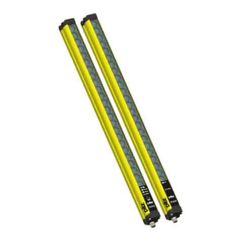
Safety light curtain
GETTING STARTED
1003068-EN-01
SAFETY GUIDELINES
To ensure correct and safe use of the safety light curtains
of the PSEN op4F/H-A-series, the following instructions have to be observed.
•The system intended to stop the machine must be electrically controllable.
•The safety system at the machine must be able to stop any hazardous machine movement
−
within the entire stopping time of the machine T,
−
in accordance with the details in chapter 1.2.3 of the operating manual (see CD provided),
−
and in each phase of the processing cycle.
•The safety light curtains may only be installed and connected by qualified personnel. It is essential to
follow the instructions provided in the relevant sections of the manuals provided (see Chapters 2, 3, 4
and 5) and to comply with the applicable directives.
•The safety light curtain must be installed securely so that access the danger zone is not possible without
interrupting the light axes (see chapter 2 and 3 of the operating manual).
•Only qualified personnel with appropriate knowledge of all the operating procedures of the safety light
curtain should be permitted to work within the danger zone.
•The operating elements for the TEST, RESET/RESTART and OVERRIDE functions have to be arranged
outside the protected field, so that the operator can control the corresponding area at any time.
•Instructions provided for correct operation must be strictly followed before switching on the light curtain.
Precautionary measures when selecting and installing
Ensure that the safety level guaranteed by the light curtain is compatible with the actual hazard
of the machine to be monitored, in accordance with the standards EN 954-1 and EN 13849-1.
•The outputs (OSSD) of the light curtain have to be connected as safety inputs and not in the normal
control circuit. The machine must have a separate START control.
•The resolution of the light curtain has to be less that the objects to be detected.
•The light curtain must be installed in an environment that complies with the technical properties stated
in Chapter 10 "Technical data" of the operating manual (see CD provided).
•Avoid installing the device, particularly the receiver on the front, close to particularly intense and/or
flashing light sources.
•Strong electromagnetic interference could adversely affect the correct operation of the light curtain.
Consider this carefully, seeking the advice of Pilz's technical customer services.
•Smoke, mist or dust in the air in the working environment can reduce the operating range of the light
curtain considerably.
•Sudden, large-scale temperature variations with very low peak values can generate a slight layer of
condensation on the light curtain's lens, adversely affecting its function.
•Reflective surfaces close to the beams emitted from the protective device (whether from above, below or
from the side) can cause passive reflections that adversely affect the operation of the light curtain.
•The protective device must be positioned at a distance that exceeds the minimum safety distance S or
that corresponds to it, which guarantees that the operator cannot reach the danger zone until the
hazardous machine movement of the object has come to a standstill by triggering the light curtain.
When the safety distance is not maintained, the safety function of the light curtain could be
adversely affected or cancelled. A detailed description of the safety distance calculation is to be
found in the complete operating manual (see CD provided).

21003068-EN-01
Connector - pigtail cable
PSEN opt Advanced RX Muting
18 pin
M12 12 pin
M12 5 pin
M12 connector, 12-pin:
1. 24 V (brown)
2. 0 V (blue)
3. RESET/RESTART/ALIGN (white)
4. OVERRIDE1 (green)
5. OSSD2 (pink)
6. EDM (yellow)
7. MUTING ACTIVATION (black)
8. OSSD1 (grey)
9. OVERRIDE2 (red)
10. MUTING LAMP (purple)
11. OVERRIDE STATUS (grey-pink)
12. EARTHING (red-blue)
M12 connector, 5-pin:
1. 24 V (brown)
2. MUTING2 (white)
3. 0 V (blue)
4. MUTING1 (black)
5. N.C. (grey)
PSEN opt Advanced TX
18 pin
M12 5 pin
M12 5-pin
1.
24 V (brown)
2. TEST (white) 3.
0 V (blue)
4. EARTH (black)
5. N.C.
PSEN opt Advanced RX Blanking
18 pin
M12 12 pin
M12 12-pin
1.
24 V (brown)
2. 0 V (blue)
3. RESET/RESTART/ALIGN (white)
4. TEACH IN (green)
5. OSSD2 (pink)
6.
EDM (yellow)
7.
N.C. (black)
8. OSSD1 (grey)
9. TOLERANCE (red)
10. LAMP (purple)
11. N.C. (grey-pink)
12.
EARTHING (red-blue)

1003068-EN-01 3
ALIGNMENT
The transmitter and receiver must be aligned to ensure the light curtain operates correctly. Good
alignment prevents instability due to dust deposits or vibration.
Make a check after you have installed the mechanical and electrical components correctly, and check the
results in accordance with the following tables. To start the alignment mode of the light curtain, the
RESET/RESTART/ALIGN input has to be activated while the light curtain is activated, until the red OSSD
LED starts flashing.
The alignment is perfect when the light axes emitted by the first and the last transmitter correspond to
the light axes at the relevant elements of the receiver.
The first beam (beside the connector) and the last beam are used for optical synchronisation (SYNC).
Information
Configuration LED
RX
Alignment status
OSSD status -
normal operation
No sync, check SYNC1
NO OFF
SYNC1aligned
NO OFF
SYNC2aligned
NO OFF
One or several
intermediate beams
are not aligned
NO OFF
All light axes are
aligned
LOW ON
All light axes are
aligned
ON
All light axes are
aligned
ON
All light axes are
aligned
EXCELLENT ON
AHold the receiver in a stable position and align the transmitter until the yellow SYNC1 LED goes out.
This state confirms that the first synchronisation beam has been aligned.
BRotate the transmitter around the axis of the lower lens until the yellow SYNC2 LED goes out.
C For precision adjustment, alternately make minor movements of the transmitter and receiver to achieve the optimum
quality ().
D Fix both units. Check that the LEVEL of the receiver does not decrease in quality, and that the light axes are not
interrupted. Then check that all LEDs on the LEVEL LED go out, even if only one beam is interrupted.
For checking, use the cylindrical test object PSEN op Testpiece F 14mm or PSEN op Testpiece F 30mm that
corresponds to the diameter of the configured resolution (see chapter 2.2.5 “Inspections following a first-time
installation” of the operating manual).
E Switch off the light curtain pair and then switch it back on in normal operating mode.
The degree of alignment is always indicated on displays even during normal operation of the light curtain (see
chapter 8.1 of the operating manual).
Once the light curtain has been aligned and fastened appropriately, the LED display proves useful for checking the
alignment and displaying any change in the ambient conditions (e.g. dust).

41003068-EN-01
SETTING OF BASIC CONFIGURATION (BCM)
The light curtain can switch to the basic configuration mode during normal operation. After
configuration and when the button "CONFIRM" is pressed, the light curtain starts up in
normal operating mode in the new configuration. Particular attention is required during
administration and use of the basic configuration.
The muting timeout "infinite" does not meet the requirements of the standard IEC
61496-
1. For this reason, any possible hazards must be taken into account and the
appropriate preventive measures have to be taken before selecting the option
"infinite".
1To open the mode of basic configuration press the CONFIRM button and hold it down.
The system runs through a test cycle. During this test cycle, ALL LEDs must light up in sequence
from 1 to 8 . The current configuration is then displayed.
2Use the SELECT function to choose the function that is to be set. The LED for the selected function
will flash.
3
Now configure the selected function by pressing the ENABLE button (LED lights/goes out).
4
Repeat steps 2 and 3 until the required configuration is displayed.
5Press the CONFIRM button and keep it held down to save the new configuration.
List of RX functions in muting mode
(LED3 lights up yellow)
Function LED
No.
Setting
(Standard setting in bold)
Status of LED
Coding 2Code 1
Code 2
No code
Selection of muting/blanking 3Muting
Blanking
EDM 4Activated
Deactivated
Restart mode 5Auto
Manual
Muting direction 6
T (bidirectional)
L (one-directional)
Muting Timeout 710 min
Infinite
Override sensor 8
Level
Edge

1003068-EN-01 5
Function list in blanking mode (LED3 OFF)
Function LED
No.
Setting
(Default in bold)
Status of LED
Coding 2Code 1
Code 2
No code
Selection of muting/blanking 3Muting
Blanking
EDM 4Activated
Deactivated
Restart mode 5
Auto
Manual
Selection of floating blanking
6-7 Floating blanking disabled
Floating blanking 1 beam
Floating blanking 2 beams
Red. resolution 4 beams
Selection of fixed blanking 81 fixed blanking zone
2 fixed blanking zones
List of TX functions
Function LED
No. Setting (Default in bold) Status of LED
Coding 2Code 1
Code 2
No code
Selection of operating range 3Long
Reduced
DIAGNOSTIC FUNCTION
The operator can check the operating conditions of the safety light curtains via the 8 LEDs that are
aligned at the RX and the TX unit. The image below displays all the display modes of the LEDs: OFF, LIT,
FLASHING, NO MEANING (can be switched on or off according to the selected operating mode)
RX UNIT
Operating
mode light
curtain Information
Recommended procedure
Normal operating
mode
Interlock
Free beams. The operator can start up the light
curtain in normal operating mode
again by activating the RESTART
Interlock
Beams interrupted. The operator has to remove any
objects from the protected field
before he can activate the RESTART
OSSD switched on
OSSD switched off
CODE1

61003068-EN-01
RX UNIT
Operating
mode light
curtain Information
Recommended procedure
Normal operating
mode
OSSD switched off
CODE2
OSSD switched off
No CODE
EDM active
ACM active
ACM is currently
being used
Configuration process running via
PC, follow software instructions
Error
Error at OSSD Activate the RESET. If the error
should persist, please contact Pilz
customer services.
Error
microprocessor/s. Activate the RESET. If the error
should persist, please contact Pilz
customer services.
Error optical
system Activate the RESET. If the error
should persist, please contact Pilz
customer services.
EDM error
Check EDM feedback loop and EDM
configuration. Activate the RESET.
Restart error
Check RESTART connection.
Activate the RESET.
Communication
error Check the cascading connection and
check that the terminator cap is
installed correctly. Activate the
RESET.
BCM configuration
error Perform basic configuration again.
If the error should persist, please
contact Pilz customer services.
ACM configuration
error Perform advanced configuration
again. If the error should persist,
please contact Pilz customer
services.
General error -
cannot be reset Switch light curtain on/off. The
indicated error code does not
correspond to the above error with
lit LED.
Light curtain
switched off Supply error Check the power supply connection.
If the error should persist, please
contact Pilz customer services.

1003068-EN-01 7
RX UNIT
Operating
mode light
curtain Information
Recommended procedure
RX UNIT (BLANKING ONLY)
Normal operation
Blanking invalid
(OSSD off)
Blanking zones not observed. Re-
configure blanking (teach in if BCM)
Blanking valid
(OSSD on)
Tolerance BCM
active Check the efficient resolution for
the light curtain and the intended
activation of the tolerance function.
RX UNIT (MUTING ONLY)
Normal operation
Muting active When OSSD is switched off without
designated active muting, check the
configuration of the partial muting.
Override active
Override call status
Activate the override button to
force OSSDs to light.
Override time error Check the override activation
sequence. Check the override
connector.
Lamp error
TX UNIT
Operating
mode light
curtain Information
Procedure
Normal operation
During operation
TEST
In the event of unwanted tests, check
the connection of the test input.
Beams
reduced range
Beams
long range
No code
Code 1
Code 2
Error
Error
microprocessor/s. Activate the RESET. If the error should
persist, please contact Pilz customer
services.
Optical system error Activate the RESET. If the error should
persist, please contact Pilz customer
services.

81003068-EN-01
TX UNIT
Operating
mode light
curtain Information
TST
SR
LR
CODE
PWR
Procedure
Error
BCM configuration
error Perform basic configuration again.
If the error should persist, please
contact Pilz customer services.
Communication
error Check the cascading connection
and check that the terminator cap
is installed correctly. Activate the
RESET.
General error -
cannot be reset Switch light curtain on/off. The
indicated error code corresponds to
the above error with lit LED.
DOWNLOAD PSENopt Configurator
URL
www.pilz.com/Downloads
Search term PSENopt Configurator
Pilz GmbH & Co. KG
Felix-Wankel-Straße 2, 73760 Ostfildern, Germany
Tel: +49 711 3409-0 - Fax: +49 711 3409-133
Pilz®, PIT®, PMI®, PNOZ®, Primo®, PSEN®, PSS®, PVIS®, SafetyBUS p®, SafetyEYE®, SafetyNET p®, the spirit of safety® are registered and protected trademarks of Pilz
GmbH & Co. KG in some countries.
© Copyright Pilz 2013-09
Table of contents
Other Pilz Safety Equipment manuals

Pilz
Pilz PSEN op4F-A Series User manual

Pilz
Pilz PSEN opII3B Series User manual

Pilz
Pilz 19 964-12 User manual

Pilz
Pilz PSS WIN-PRO User manual

Pilz
Pilz PIT si1.2 User manual

Pilz
Pilz PNOZ ms2p TTL User manual

Pilz
Pilz PNOZ mi1p User manual

Pilz
Pilz PNOZ mo5p User manual

Pilz
Pilz PSS Series User manual

Pilz
Pilz PSEN cs3.1a User manual