Pioneer HD-V9000 User manual

ORDER NO.
PIONEER CORPORATION 1-1, Shin-ogura, Saiwai-ku, Kawasaki-shi, Kanagawa 212-0031, Japan
PIONEER ELECTRONICS (USA) INC. P.O. Box 1760, Long Beach, CA 90801-1760, U.S.A.
PIONEER EUROPE NV Haven 1087, Keetberglaan 1, 9120 Melsele, Belgium
PIONEER ELECTRONICS ASIACENTRE PTE. LTD. 253 Alexandra Road, #04-01, Singapore 159936
PIONEER CORPORATION
2010
2010 Printed in Japan
HD-V9000
RRV4037
HD VIDEO SYSTEM
HD-V9000
THIS MANUAL IS APPLICABLE TO THE FOLLOWING MODEL(S) AND TYPE(S).
Model Type Power Requirement Remarks
HD-V9000 CU AC 120 V
HD-V9000 Y8AC 220 V to 240 V
HD-V9000 K5 AC 220 V
For details, refer to "Important Check Points for good servicing".
K-IZK FEB.
w
w
w
.
x
i
a
o
y
u
1
6
3
.
c
o
m
Q
Q
3
7
6
3
1
5
1
5
0
9
9
2
8
9
4
2
9
8
T
E
L
1
3
9
4
2
2
9
6
5
1
3
9
9
2
8
9
4
2
9
8
0
5
1
5
1
3
6
7
3
Q
Q
TEL 13942296513 QQ 376315150 892498299
http://www.xiaoyu163.com

2HD-V9000
12 3 4
A
B
C
D
E
F
12 3 4
SAFETY INFORMATION
1. SAFETY PRECAUTIONS
The following check should be performed for the
continued protection of the customer and service
technician.
LEAKAGE CURRENT CHECK
Measure leakage current to a known earth ground
(water pipe, conduit, etc.) by connecting a leakage
current tester such as Simpson Model 229-2 or
equivalent between the earth ground and all exposed
metal parts of the appliance (input/output terminals,
screwheads, metal overlays, control shaft, etc.). Plug
the AC line cord of the appliance directly into a 120V
AC 60 Hz outlet and turn the AC power switch on. Any
current measured must not exceed 0.5 mA.
ANY MEASUREMENTS NOT WITHIN THE LIMITS
OUTLINED ABOVE ARE INDICATIVE OF A POTENTIAL
SHOCK HAZARD AND MUST BE CORRECTED BEFORE
RETURNING THE APPLIANCE TO THE CUSTOMER.
2. PRODUCT SAFETY NOTICE
Many electrical and mechanical parts in the appliance
have special safety related characteristics. These are
often not evident from visual inspection nor the protection
afforded by them necessarily can be obtained by using
replacement components rated for voltage, wattage, etc.
Replacement parts which have these special safety
characteristics are identified in this Service Manual.
Electrical components having such features are
identified by marking with a >on the schematics and on
the parts list in this Service Manual.
The use of a substitute replacement component which
does not have the same safety characteristics as the
PIONEER recommended replacement one, shown in the
parts list in this Service Manual, may create shock, fire,
or other hazards.
Product Safety is continuously under review and new
instructions are issued from time to time. For the latest
information, always consult the current PIONEER Service
Manual. A subscription to, or additional copies of,
PIONEER Service Manual may be obtained at a nominal
charge from PIONEER.
Leakage
current
tester
Reading should
not be above
0.5 mA
Device
under
test
Test all
exposed metal
surfaces
Also test with
plug reversed
(Using AC adapter
plug as required)
Earth
ground
AC Leakage Test
(FOR USA MODEL ONLY)
WARNING
This product may contain a chemical known to the State of California to cause cancer, or birth defects or other reproductive
harm.
Health & Safety Code Section 25249.6 - Proposition 65
NOTICE
(FOR CANADIANMODEL ONLY)
Fuse symbols (fast operating fuse) and/or (slow operating fuse) on PCB indicate that replacement parts must
be of identical designation.
REMARQUE
(POUR MODÈLE CANADIENSEULEMENT)
Les symboles de fusible (fusible de type rapide) et/ou (fusible de type lent) sur CCI indiquent que les pièces
de remplacement doivent avoir la même désignation.
This service manual is intended for qualified service technicians ; it is not meant for the casual do-it-
yourselfer. Qualified technicians have the necessary test equipment and tools, and have been trained
to properly and safely repair complex products such as those covered by this manual.
Improperly performed repairs can adversely affect the safety and reliability of the product and may
void the warranty. If you are not qualified to perform the repair of this product properly and safely, you
should not risk trying to do so and refer the repair to a qualified service technician.
w
w
w
.
x
i
a
o
y
u
1
6
3
.
c
o
m
Q
Q
3
7
6
3
1
5
1
5
0
9
9
2
8
9
4
2
9
8
T
E
L
1
3
9
4
2
2
9
6
5
1
3
9
9
2
8
9
4
2
9
8
0
5
1
5
1
3
6
7
3
Q
Q
TEL 13942296513 QQ 376315150 892498299
http://www.xiaoyu163.com

3
HD-V9000
56 7 8
56 7 8
A
B
C
D
E
F
[Important Check Points for Good Servicing]
In this manual, procedures that must be performed during repairs are marked with the below symbol.
Please be sure to confirm and follow these procedures.
1. Product safety
Please conform to product regulations (such as safety and radiation regulations), and maintain a safe servicing environment by
following the safety instructions described in this manual.
1 Use specified parts for repair.
Use genuine parts. Be sure to use important parts for safety.
2 Do not perform modifications without proper instructions.
Please follow the specified safety methods when modification(addition/change of parts) is required due to interferences such as
radio/TVinterference and foreign noise.
3 Make sure the soldering of repaired locations is properly performed.
When you solder while repairing, please be sure that there are no cold solder and other debris.
Soldering should be finished with the proper quantity. (Refer to the example)
4 Make sure the screws are tightly fastened.
Please be sure that all screws are fastened, and that there are no loose screws.
5 Make sure each connectors are correctly inserted.
Please be sure that all connectors are inserted, and that there are no imperfect insertion.
6 Make sure the wiring cables are set to their original state.
Please replace the wiring and cables to the original state after repairs.
In addition, be sure that there are no pinched wires, etc.
7 Make sure screws and soldering scraps do not remain inside the product.
Please check that neither solder debris nor screws remain inside the product.
8 There should be no semi-broken wires, scratches, melting, etc.on the coating of the power cord.
Damaged power cords may lead to fire accidents, so please be sure that there are no damages.
If you find a damaged power cord, please exchange it with a suitable one.
9 There should be no spark traces or similar marks on the power plug.
When spark traces or similar marks are found on the power supply plug, please check the connection and advise on secure
connections and suitable usage. Please exchange the power cord if necessary.
aSafe environment should be secured during servicing.
When you perform repairs, please pay attention to static electricity, furniture, household articles, etc.in order to prevent injuries.
Please pay attention to your surroundings and repair safely.
2. Adjustments
To keep the original performance of the products, optimum adjustments and confirmation of characteristics within specification.
Adjustments should be performed in accordance with the procedures/instructions described in this manual.
4. Cleaning
For parts that require cleaning, such as optical pickups, tape deck heads, lenses and mirrors used in projection monitors, proper
cleaning should be performed to restore their performances.
3. Lubricants, Glues, and Replacement parts
Use grease and adhesives that are equal to the specified substance.
Make sure the proper amount is applied.
5. Shipping mode and Shipping screws
To protect products from damages or failures during transit, the shipping mode should be set or the shipping screws should be
installed before shipment. Please be sure to follow this method especially if it is specified in this manual.
w
w
w
.
x
i
a
o
y
u
1
6
3
.
c
o
m
Q
Q
3
7
6
3
1
5
1
5
0
9
9
2
8
9
4
2
9
8
T
E
L
1
3
9
4
2
2
9
6
5
1
3
9
9
2
8
9
4
2
9
8
0
5
1
5
1
3
6
7
3
Q
Q
TEL 13942296513 QQ 376315150 892498299
http://www.xiaoyu163.com

4HD-V9000
12 3 4
A
B
C
D
E
F
12 3 4
CONTENTS
1. SERVICE PRECAUTIONS ....................................................................................................................................................6
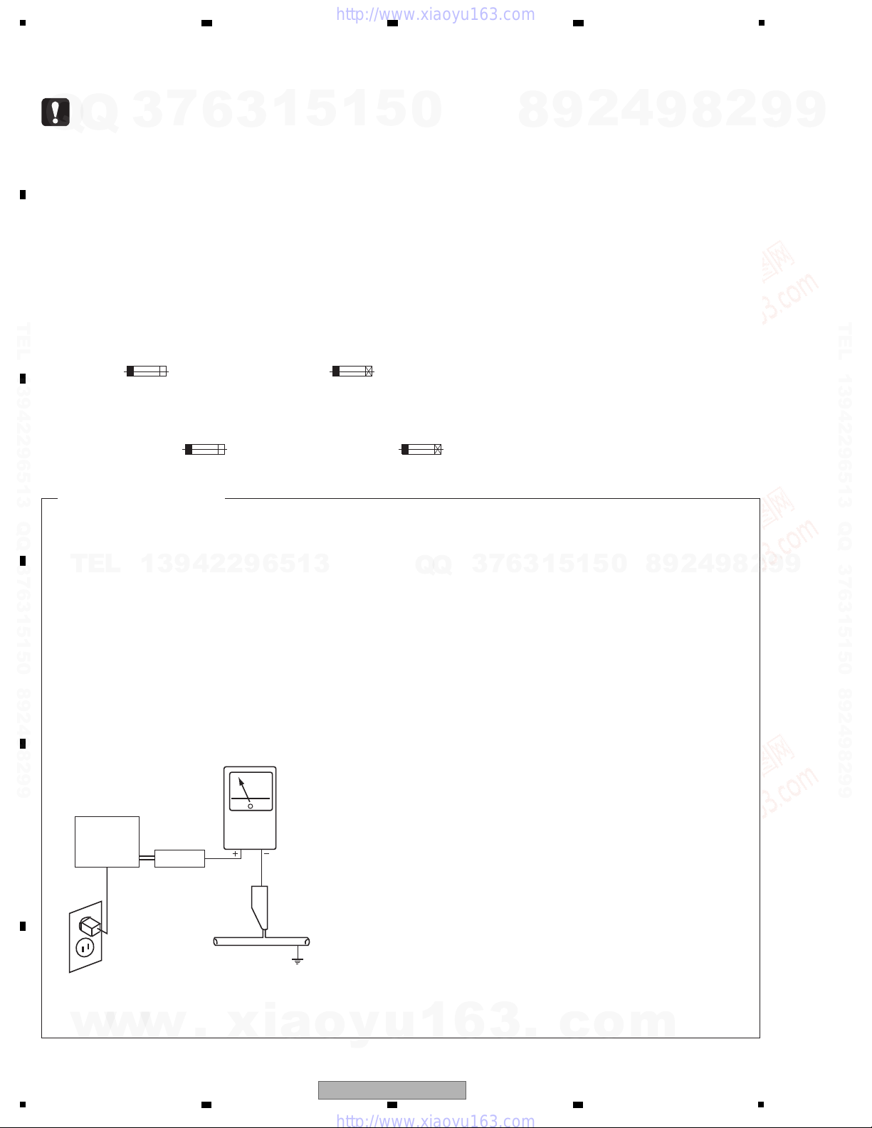
1.1 NOTES ON SOLDERING ...............................................................................................................................................6
1.2 ABOUT BONNET............................................................................................................................................................6
1.3 STORAGE OF USER-SETTING DATA ...........................................................................................................................7
1.4 NOTES ON REPLACE OF THE DECM ASSY ...............................................................................................................7
1.5 EEPROM IN THE DECM ASSY AND MAC ADDRESS..................................................................................................7
1.6 NOTES ON REPLACE OF THE FLCB ASSY.................................................................................................................7
2. SPECIFICATIONS .................................................................................................................................................................8
2.1 SPECIFICATIONS...........................................................................................................................................................8
2.2 PLAYABLE FILE FORMATS............................................................................................................................................9
2.3 PANEL FACILITIES.......................................................................................................................................................11
3. BASIC ITEMS FOR SERVICE.............................................................................................................................................14
3.1 CHECK POINTS AFTER SERVICING..........................................................................................................................14
3.2 PCB LOCATIONS .........................................................................................................................................................15
3.3 JIGS LIST......................................................................................................................................................................16
3.4 CONTENTS FOR SERVICE .........................................................................................................................................16
4. BLOCK DIAGRAM...............................................................................................................................................................18
4.1 OVERALL WIRING DIAGRAM......................................................................................................................................18
4.2 SIGNAL BLOCK DIAGRAM ..........................................................................................................................................20
4.3 POWER SUPPLY BLOCK DIAGRAM ...........................................................................................................................22
5. DIAGNOSIS.........................................................................................................................................................................24
5.1 POWER ON SEQUENCE .............................................................................................................................................24
5.2 RESET SEQUENCE.....................................................................................................................................................25
5.3 TROUBLESHOOTING ..................................................................................................................................................26
5.4 ERROR SPECIFICATIONS...........................................................................................................................................32
6. SERVICE MODE .................................................................................................................................................................36
6.1 SERVICE SCREEN.......................................................................................................................................................36
6.2 INITIALIZATION ............................................................................................................................................................43
6.3 MEMORY CHECK.........................................................................................................................................................44
6.4 ABOUT THE DEVICE ...................................................................................................................................................46
7. DISASSEMBLY....................................................................................................................................................................47
8. EACH SETTING AND ADJUSTMENT ................................................................................................................................50
8.1 NECESSARY SETTING ITEMS....................................................................................................................................50
8.2 REWRITING THE SERIAL NUMBER ...........................................................................................................................50
8.3 UPDATING OF THE FIRMWARE..................................................................................................................................51
8.4 ITEMS FOR WHITCH USERS SETTING IS AVAILABLE.............................................................................................53
9. EXPLODED VIEWS AND PARTS LIST...............................................................................................................................54
9.1 PACKING SECTION......................................................................................................................................................54
9.2 EXTERIOR SECTION...................................................................................................................................................56
9.3 FRONT PANEL SECTION.............................................................................................................................................58
w
w
w
.
x
i
a
o
y
u
1
6
3
.
c
o
m
Q
Q
3
7
6
3
1
5
1
5
0
9
9
2
8
9
4
2
9
8
T
E
L
1
3
9
4
2
2
9
6
5
1
3
9
9
2
8
9
4
2
9
8
0
5
1
5
1
3
6
7
3
Q
Q
TEL 13942296513 QQ 376315150 892498299
http://www.xiaoyu163.com

5
HD-V9000
56 7 8
56 7 8
A
B
C
D
E
F
10. SCHEMATIC DIAGRAM.................................................................................................................................................... 60
10.1 DECM SERVICE ASSY (1/18).................................................................................................................................... 60
10.2 DECM SERVICE ASSY (2/18).................................................................................................................................... 66
10.3 DECM SERVICE ASSY (3/18).................................................................................................................................... 68
10.4 DECM SERVICE ASSY (4/18).................................................................................................................................... 70
10.5 DECM SERVICE ASSY (5/18).................................................................................................................................... 72
10.6 DECM SERVICE ASSY (6/18).................................................................................................................................... 78
10.7 DECM SERVICE ASSY (7/18).................................................................................................................................... 80
10.8DECM SERVICE ASSY (8/18).................................................................................................................................... 82
10.9 DECM SERVICE ASSY (9/18).................................................................................................................................... 88
10.10 DECM SERVICE ASSY (10/18)................................................................................................................................ 90
10.11 DECM SERVICE ASSY (11/18)................................................................................................................................ 92
10.12 DECM SERVICE ASSY (12/18)................................................................................................................................ 94
10.13 DECM SERVICE ASSY (13/18)................................................................................................................................ 96
10.14 DECM SERVICE ASSY (14/18)................................................................................................................................ 98
10.15 DECM SERVICE ASSY (15/18).............................................................................................................................. 100
10.16 DECM SERVICE ASSY (16/18).............................................................................................................................. 102
10.17 DECM SERVICE ASSY (17/18).............................................................................................................................. 104
10.18DECM SERVICE ASSY (18/18).............................................................................................................................. 106
10.19 SDCB ASSY ........................................................................................................................................................... 108
10.20 USBB ASSY ........................................................................................................................................................... 110
10.21 HPVB ASSY ........................................................................................................................................................... 112
10.22 KEYB ASSY............................................................................................................................................................ 114
10.23 FLCB ASSY (1/2).................................................................................................................................................... 116
10.24 FLCB ASSY (2/2).................................................................................................................................................... 118
10.25 POWER SUPPLY ASSY ......................................................................................................................................... 120
10.26 WAVEFORMS......................................................................................................................................................... 122
10.27 THE DIFFERENCE TERMINAL NAME LIST ......................................................................................................... 126
11. PCB CONNECTION DIAGRAM ...................................................................................................................................... 131
11.1 DECM SERVICE ASSY............................................................................................................................................ 132
11.2 SDCB ASSY ............................................................................................................................................................. 136
11.3 USBB ASSY ............................................................................................................................................................. 137
11.4 HPVB and KEYB ASSYS ......................................................................................................................................... 138
11.5 FLCB ASSY.............................................................................................................................................................. 140
11.6 POWER SUPPLY ASSY ........................................................................................................................................... 142
12. PCB PARTS LIST............................................................................................................................................................ 144
w
w
w
.
x
i
a
o
y
u
1
6
3
.
c
o
m
Q
Q
3
7
6
3
1
5
1
5
0
9
9
2
8
9
4
2
9
8
T
E
L
1
3
9
4
2
2
9
6
5
1
3
9
9
2
8
9
4
2
9
8
0
5
1
5
1
3
6
7
3
Q
Q
TEL 13942296513 QQ 376315150 892498299
http://www.xiaoyu163.com

6HD-V9000
12 3 4
A
B
C
D
E
F
12 3 4
1. SERVICE PRECAUTIONS
1.1 NOTES ON SOLDERING
1.2 ABOUT BONNET
• For environmental protection, lead-free solder is used on the printed circuit boards mounted in this unit.
Be sure to use lead-free solder and a soldering iron that can meet specifications for use with lead-free solders for repairs
accompanied by reworking of soldering.
• Compared with conventional eutectic solders, lead-free solders have higher melting points, by approximately 40 ºC.
Therefore, for lead-free soldering, the tip temperature of a soldering iron must be set to around 373 ºC in general, although
the temperature depends on the heat capacity of the PC board on which reworking is required and the weight of the tip of
the soldering iron.
Do NOT use a soldering iron whose tip temperature cannot be controlled.
Compared with eutectic solders, lead-free solders have higher bond strengths but slower wetting times and higher melting
temperatures (hard to melt/easy to harden).
The following lead-free solders are available as service parts:
• Parts numbers of lead-free solder:
GYP1006 1.0 in dia.
GYP1007 0.6 in dia.
GYP1008 0.3 in dia.
The bonnet is provided as the Bonnet kit (CU: GXX1295, K5: GXX1296), which contains a bonnet and a caution label as
service parts.
The enclosed caution label is required by law.
Make certain that you attach it to the bonnet, as shown in the figure below.
Caution label
(Orientation of letters on the label)
(CU and K5 model only)
w
w
w
.
x
i
a
o
y
u
1
6
3
.
c
o
m
Q
Q
3
7
6
3
1
5
1
5
0
9
9
2
8
9
4
2
9
8
T
E
L
1
3
9
4
2
2
9
6
5
1
3
9
9
2
8
9
4
2
9
8
0
5
1
5
1
3
6
7
3
Q
Q
TEL 13942296513 QQ 376315150 892498299
http://www.xiaoyu163.com

7
HD-V9000
56 7 8
56 7 8
A
B
C
D
E
F
1.3 STORAGE OF USER-SETTING DATA
1.4 NOTES ON REPLACE OF THE DECM ASSY
1.5 EEPROM IN THE DECM ASSY AND MAC ADDRESS
1.6 NOTES ON REPLACE OF THE FLCB ASSY
Be sure to store the data shown below in a USB memory device before repairing/inspecting the product or downloading, in
case of accidental initialization of user-setting data.
Setup (video /audio /initial /network) data, Playlist, and Schedule
For details on how to store data, refer to the operating instructions.
After replacing the DECM Assy, follow the steps below.
(1) Initialization: Reset the settings to the factory preset values, referring to "6.2 INITIALIZATION."
(2) Loading of user settings: Load the following user settings stored before replacement:
Setup (Video/Audio/Initial/Network), Playlist, and Schedule.
For details on how to load, refer to the operation manual.
(3) Resetting the HOUR METER: Reset POWER ONTIME 2 of the HOUR METER. For resetting, see "HOUR METER" in "4
What can be checked on the service screens," in "6.1 SERVICE SCREEN."
When returning the repaired product to the customer, be sure to inform him/her that the MAC address has been changed
because of the replacement of the DECM Assy.
NEVER replace the EEPROM (IC3506) in the DECM Assy during servicing. If the EEPROM is assumed to be defective,
replace the whole DECM Assy. The MAC address inherent to a product is stored in this IC. The MAC address can only be
written to the IC at the factory.
After replacement of the FLCB Assy, be sure to reset the settings shown below.
• Serial No.: For resetting, see "8.1 REWRITING THE SERIAL NO."
• Destination: For resetting, see "SHIP SETTING" in "4. What can be checked on the service screens," in "6.1 SERVICE
SCREEN."
• Time data (clock): For resetting, open the Setting Menu and select Initial Settings, Options, then Clock Setting.
For details, refer to the operating instructions of the unit.
w
w
w
.
x
i
a
o
y
u
1
6
3
.
c
o
m
Q
Q
3
7
6
3
1
5
1
5
0
9
9
2
8
9
4
2
9
8
T
E
L
1
3
9
4
2
2
9
6
5
1
3
9
9
2
8
9
4
2
9
8
0
5
1
5
1
3
6
7
3
Q
Q
TEL 13942296513 QQ 376315150 892498299
http://www.xiaoyu163.com

8HD-V9000
12 3 4
A
B
C
D
E
F
12 3 4
2. SPECIFICATIONS
2.1 SPECIFICATIONS
External Dimensions
CU: AC 120 V, 60 Hz
CU: 30 W
Y8, K5: 32 W
CU: 40 A or less
Y8, K5: 70 A or less (Hot start), 22 A or less (Hot switching)
Y8: AC 220 V to 240 V, 50 Hz/60 Hz
K5: AC 220 V 60 Hz
w
w
w
.
x
i
a
o
y
u
1
6
3
.
c
o
m
Q
Q
3
7
6
3
1
5
1
5
0
9
9
2
8
9
4
2
9
8
T
E
L
1
3
9
4
2
2
9
6
5
1
3
9
9
2
8
9
4
2
9
8
0
5
1
5
1
3
6
7
3
Q
Q
TEL 13942296513 QQ 376315150 892498299
http://www.xiaoyu163.com

14 HD-V9000
12 3 4
A
B
C
D
E
F
12 3 4
3. BASIC ITEMS FOR SERVICE
3.1 CHECK POINTS AFTER SERVICING
No. Procedures Points to be checked
1
2
3
4
5
Confirm the versions of the firmware either by holding the
Display key on the main unit pressed for several seconds or by
displaying the Player Property screen from the Setup menu on
the main unit.
Check the update history of each program.
Confirm whether the customer complain has been solved. The customer complain must not be reappeared.
Video, audio and operations must be normal.
Confirm that content stored in the SD card (special tool) can be
played back.
[Files to be played back]
H.264: TH60008_M_10, TH71001_L_20,
TH60010_L_45, TH10753_A_20
MPEG2: TM15053_M_20, TM71001_D_30, TM15051_D_40,
TM71002_M_30, TM71003_L_55, TM71004_L_55,
TM15050_M_15, TM15054_M_15
Video, audio and search operations must be normal.
Confirm the data transmission rate of the SD card (special tool)
in Service mode.
Normal value as reference:
Read rate of 140 Mbps or higher upon measurement in Stop mode
Confirm the device connected to the USB port in Service mode. The device connected to the USB port must be displayed.
6Confirm the LANfunctions in Service mode. The MAC address and IP address must be displayed.
Items to be checked after servicing / HD video system
To keep the product quality after servicing, confirm recommended check points shown below.
Item to be checked regarding video Item to be checked regarding audio
Block noise Distortion
Horizontal noise Noise
Dot noise Volume too low
Disturbed image (video jumpiness) Volume too high
Too dark Volume fluctuating
Too bright Sound interrupted
Color disappearance
Mottled color
See the table below for the items to be checked regarding video and audio.
No. Procedures Points to be checked
1Confirmation of the external sync function:
Confirm that the video output signal is synchronized with the
same external input (NTSC/PAL or HD sync signal) as that
employed in the customer's usage environment.
The video output signal must not be out of sync.
Items to be checked, according to usage environment
w
w
w
.
x
i
a
o
y
u
1
6
3
.
c
o
m
Q
Q
3
7
6
3
1
5
1
5
0
9
9
2
8
9
4
2
9
8
T
E
L
1
3
9
4
2
2
9
6
5
1
3
9
9
2
8
9
4
2
9
8
0
5
1
5
1
3
6
7
3
Q
Q
TEL 13942296513 QQ 376315150 892498299
http://www.xiaoyu163.com

15
HD-V9000
56 7 8
56 7 8
A
B
C
D
E
F
3.2 PCB LOCATIONS
1..ETCB ASSY DWM2340
2..FLCB ASSY DWZ1208
2..KEYB ASSY DWZ1209
2..HPVB ASSY DWZ1210
2..USBB ASSY DWZ1211
1..SDCB ASSY DWX2950
1..DECM SERVICE ASSY DXX2610
>1..POWER SUPPLY ASSY DWR1452
1..LCD Module DWG1669
Mark No. Description Part No. Mark No. Description Part No.
LIST OF ASSEMBLIES
NOTES:
-
Parts marked by “NSP” are generally unavailable because they are not in our Master Spare Parts List.
-
The >mark found on some component parts indicates the importance of the safety factor of the part.
Therefore, when replacing, be sure to use parts of identical designation.
E
KEYB Assy
D
HPVB Assy
C
USBB Assy
B
SDCB Assy
LCD Module
A
DECM SERVICE Assy
F
FLCB Assy
G
POWER SUPPLY Assy
• Rear view
w
w
w
.
x
i
a
o
y
u
1
6
3
.
c
o
m
Q
Q
3
7
6
3
1
5
1
5
0
9
9
2
8
9
4
2
9
8
T
E
L
1
3
9
4
2
2
9
6
5
1
3
9
9
2
8
9
4
2
9
8
0
5
1
5
1
3
6
7
3
Q
Q
TEL 13942296513 QQ 376315150 892498299
http://www.xiaoyu163.com

16 HD-V9000
12 3 4
A
B
C
D
E
F
12 3 4
3.3 JIGS LIST
3.4 CONTENTS FOR SERVICE
Jigs List
Jig Name Part No. Purpose of use
SD card with HD contents GGF1645 For quality and operation checks
Remote control unit dedicated for servicing GGF1595 For entering Service mode
RS-232C cable For checking memory
or rewriting the serial No.
Terminal software For checking memory
or rewriting the serial No.
Program for switching to Memory Check mode
For memory check
Remarks
D-sub 9 pin (female) ⇔
D-sub 9 pin (female), cross
Hyper Terminal (Tera Term, etc.)
Purpose
of Use File Name Video Angle of View Bitrate
(Mbps)
Bitrate
Type Audio Bitrate
(Kbps)
Playback
Time Remarks
Operation
check
TM15053_M_20
MPEG2
1280x720/50p 20 CBR MPEG1-Layer2 224 30 s Color bars, horizontal scroll, music
Recommended parameter stream
TM71001_D_30 1280x720/59.94p 30 CBR Dolby Digital 384 30 s Color bars, horizontal scroll, music
TM15051_D_40 1920x1080/50i 40 CBR Dolby Digital 384 30 s Color bars, horizontal scroll, music
Recommended parameter stream
TM71002_M_30 1920x1080/59.94i 30 CBR MPEG1-Layer2 384 30 s Color bars, horizontal scroll, music
TM71003_L_55 1920x1080/50i 55 CBR LPCM - 30 s Color bars, horizontal scroll, music
Recommended parameter stream
TM71004_L_55 1920x1080/59.94i 55 CBR LPCM - 30 s Color bars, horizontal scroll, music
Recommended parameter stream
TM15050_M_15 720x480/59.94i 15 CBR MPEG1-Layer2 224 30 s Color bars, horizontal scroll, music
Recommended parameter stream
TM15054_M_15 720x576/50i 15 CBR MPEG1-Layer2 224 30 s Color bars, horizontal scroll, music
Recommended parameter stream
TH60008_M_10
H.264
1280x720/50p 10 CBR MPEG1-Layer2 224 30 s Color bars, horizontal scroll, music
Recommended parameter stream
TH71001_L_20 1280x720/59.94p 20 CBR LPCM - 30 s Color bars, horizontal scroll, music
TH60010_L_45 1920x1080/50i 45 CBR LPCM - 30 s Color bars, horizontal scroll, music
Recommended parameter stream
TH10753_A_20 1920x1080/59.94i 20 CBR AAC 384 30 s Color bars, horizontal scroll, 1 kHz
Performance
measurement
(output level)
TM35371_M_15
MPEG2
1920x1080/59.94i 15 CBR MPEG1-Layer2 224 1 m Color Bar 100 %, Music
For measurement of the component output level
TM35372_M_15 1920x1080/50i 15 CBR MPEG1-Layer2 224 1 m Color Bar 100 %, Music
For measurement of the component output level
TM35391_M_15 1280x720/59.94p 15 CBR MPEG1-Layer2 224 1 m Color Bar 100 %, Music
For measurement of the component output level
TM35392_M_15 1280x720/50p 15 CBR MPEG1-Layer2 224 1 m Color Bar 100 %, Music
For measurement of the component output level
TM35165_L_15 720x576/50i 15 CBR LPCM - 30 s Color bars 100 %, mute (L)/10 kHz, 0 dB (R)
For measurement of the component output level
TM35147_L_15 720x480/59.94i 15 CBR LPCM - 30 s Color bars 100 %, 4 kHz 0 dB (L)/mute (R)
For measurement of the component output level
TM35368_L_15 720x576/50i 15 CBR LPCM - 30 s White 100 %, 1 kHz 0 dB(L/R)
For measurement of the composite output level
TM35136_L_15 720x480/59.94i 15 CBR LPCM - 34 s White 100 %, mute (L/R)
For measurement of the composite output level
TM35146_L_15 720x480/59.94i 15 CBR LPCM - 1 m FCC Composite, 1 kHz 0 dB (L/R)
For measurement of the audio output level
w
w
w
.
x
i
a
o
y
u
1
6
3
.
c
o
m
Q
Q
3
7
6
3
1
5
1
5
0
9
9
2
8
9
4
2
9
8
T
E
L
1
3
9
4
2
2
9
6
5
1
3
9
9
2
8
9
4
2
9
8
0
5
1
5
1
3
6
7
3
Q
Q
TEL 13942296513 QQ 376315150 892498299
http://www.xiaoyu163.com

18HD-V9000
12 3 4
A
B
C
D
E
F
12 3 4
4. BLOCK DIAGRAM
4.1 OVERALL WIRING DIAGRAM
VKN1417-A
CN6505
1
GNDD
2
V+5HP
3
GNDD
4
POWER_SW
5
HP_MUTE
6
ON/STB_LED
7
GNDD
8
V+5E
9
GNDD
10
HP_ROUT
11
GNDD
12
HP_LOOT
13
GNDD
AKM1277-A
CN6501
1
E
2
R/W
3
RS
4
VO
5
VDD
6
VSS
AKM1281-A
CN6502
1
BLK
2
BLA
3
DB7
4
DB6
5
DB5
6
DB4
7
DB3
8
DB2
9
DB1
10
DB0
DKN1545-A
CN9001
1
GNDD
2
A_AHP_LOUT
3
GNDD
4
A_AHP_ROUT
5
GNDD
6
V+5E
7
GNDD
8
ON/STB_LED
9
HP_MUTE
10
POWER_SW
11
GNDD
12
V+5HP
13
GNDD
DKN1608-A CN8201
12
34
56
78
910
1112
13
14
1516
1718
1920
2122
2324
2526
2728
29
30
3132
33
34
3536
37
38
3940
4142
4344
DKN1608-A CN6508
11:IDERST
22:GNDD
33:IDED7
44:IDED8
55:IDED6
66:IDED9
77:IDED5
88:IDED10
99:IDED4
10 10:IDED11
11 11:IDED3
12 12:IDED12
13 13:IDED2
14 14:IDED13
15 15:IDED1
16 16:IDED14
17 17:IDED0
18 18:IDED15
19 19:GNDD
20 20:NC
21 21:IODREQ
22 22:GNDD
23 23:IDEIOWR
24 24:GNDD
25 25:IDEIORD
26 26:GNDD
27 27:IDEIORDY
28 28:CSEL(GNDD)
29 29:IODACK
30 30:GNDD
31 31:IDEINT
32 32:RESERVED
33 33:IDEA0
34 34:PDIAG#
35 35:IDEA1
36 36:IDEA2
37 37:IDECS0
38 38:IDECS1
39 39:#DASP
40 40:GNDD
41 41:V+3R3D
42 42:V+3R3D
43 43:GNDD
44 44:TYPE#
VKN1931-A
CN6509
1
GNDD
2
#WP_SD
3
#CD_SD
4
#RESET_SD_USB
5
#OSC_STP
VKN1931-A
CN8202
1
GNDD
2
S_WP
3
S_CD
4
XRST
5
XOSC_STO
CN6507
AKM1276-A
1
GNDD
2
USBUP-DP
3
USBUP_DM
4
GNDD
5
V+5D
AKM1277-A
CN6002
1
V+12
2
V+12
3
V+12
4
GNDD
5
GNDD
6
GNDD
VKN1439-A CN6510
1
GNDD
2
#WOL_LAN
3
LED_LAN_ACT
4
GNDD
5
RESET_LAN_SCPU
6
EMERG_M
7
GNDD
8
NC
9
SDACT_LED
10
GNDD
11
#DTR
12
GNDD
13
MCPU_RXD2
14
GNDD
15
MCPI_TXD2
16
GNDD
17
STOP_ST
18
#RESET_STOM
19
LT1_SUB
20
XRDY_SUB
21
GNDD
22
SCK0_SUB
23
GNDD
24
RXD0_SUB
25
GNDD
26
TXD0_SUB
27
GNDD
28
PC4
29
PC3
30
PC2
31
PC1
32
ON/STB_LED
33
POWER_SW
34
NC
35
GND
CN6503 DKN1602-A
1
GNDD
2
V+5E
3
GNDD
4
V+5D_1
5
GNDD
6
V+3R3E
7
GNDD
8
V+3R3D_1
9
BLK
10
BLA
11
D7
12
D6
14
D4
15
D3
16
D2
17
D1
18
D0
19
E
20
R/W
21
RS
22
VO
23
VSS(GNDD)
13
D5
CKS5956-A
JA8201
1
SD_DATA3
2
SD_CMD
3
GND
4
VDD
5
SD_CL
6
GND2
7
SD_DATA0
8
SD_DATA1
10
SD_DET
9
SD_DATA2
12 SD_W
11 TER
KM200NA16
1
VSS
2
VDD
3
VD
4
RS
5
R/W
6
E
7
DB0
8
DB1
9
DB2
10
DB3
11
DB4
12
DB5
14
DB7
15
BLA
16
BLK
13
DB6
1
GNDD
2
V+5E
3
GNDD
4
SD ACC LED
LCD MODULE
ON/STB_KEY
HP JACK HP VR
(VKN1449-A) (DCS1094-A)
LAN
(AKP1337-A)
JA3501
(DKN1537-A)
EXT-SYNC
JA4501
DIPSW
S4504
(DSH1069-A) JA5002
(DKN1538-A)
COMPONENT OUT
(DKN1536-A)
JA5001
COMPOSITE OUT HDMI OUT
JA4001
(AKB7164-A)
JA5501
SD CARD SOCKET
DKP3802
DKP3803
DDD1412(FFC)
DWG1669-A
JA5502
(PKB1036-A)
DIGITAL
AUDIO OUT
ANALOG
AUDIO OUT
DDD1414(FFC)
(Board toBoard)
LCD_KEY
SD_LED
LAN_LED
[75ohm_Term]
[NT/PAL SW]
ON_LED
STB_LED
LCD Module Pinassign
CN6508,CN8201 44pinHeader Assign
DKP3866
-
When ordering service parts, be sure to refer to "EXPLODED VIEWS and PARTS LIST" or "PCB PARTS LIST".
-
The >mark found on some component parts indicates the importance of the safety factor of the part.
Therefore, when replacing, be sure to use parts of identical designation.
-
: The power supply is shown with the marked box.
DECM SERVICE ASSY (DXX2610)
A
A A
1/18- 18/18
BSDCB ASSY
(DWX2950)
E
DHPVB ASSY
(DWZ1210)
(VKN2076-A)
w
w
w
.
x
i
a
o
y
u
1
6
3
.
c
o
m
Q
Q
3
7
6
3
1
5
1
5
0
9
9
2
8
9
4
2
9
8
T
E
L
1
3
9
4
2
2
9
6
5
1
3
9
9
2
8
9
4
2
9
8
0
5
1
5
1
3
6
7
3
Q
Q
TEL 13942296513 QQ 376315150 892498299
http://www.xiaoyu163.com

19
HD-V9000
56 7 8
56 7 8
A
B
C
D
E
F
8765
4321
LOWER
UPPER
1
BLK
2
BLA
3
DB7
JA9501
DKN1417-A
CN9502
AKM1276-A
1
GNDD
2
USBUP-DP
3
USBUP_DM
4
GNDD
5
V+5D
AKM1277-A
CN6002
1
V+12
2
V+12
3
V+12
4
GNDD
5
GNDD
6
GNDD
JA7301
AKP1213-A
1
NC
2
RXD
3
TXD
4
DTR
5
GNDD
6
NC
7
RTS
8
CTS
9
NC
DKN1435-A
JA7302
1
GND
2
TXD
3
RXD
4
DTR
5
POWER_IN
6
SW1( )
7
SW2( )
8
SW3( )
9
SW4( )
10
SW5(ENT)
11
SW6(X)
12
SW7(Y)
13
SW8(Z)
14
D.LOAD
15
STOP_ST
RT1
F_GND
RT2
F_GND
VKN1439-A CN6510
1
GNDD
2
#WOL_LAN
3
LED_LAN_ACT
4
GNDD
5
ESET_LAN_SCPU
6
EMERG_M
7
GNDD
8
NC
9
SDACT_LED
10
GNDD
11
#DTR
12
GNDD
13
MCPU_RXD2
14
GNDD
15
MCPI_TXD2
16
GNDD
17
STOP_ST
18
#RESET_STOM
19
LT1_SUB
20
XRDY_SUB
21
GNDD
22
SCK0_SUB
23
GNDD
24
RXD0_SUB
25
GNDD
26
TXD0_SUB
27
GNDD
28
PC4
29
PC3
30
PC2
31
PC1
32
ON/STB_LED
33
POWER_SW
34
NC
35
GND
VKN1439-A CN7005
1
GNDD
2
NC
3
POWER_SW
4
ON/STB_LED
5
PC1
6
PC2
7
PC3
8
PC4
9
GNDD
10
TXD0_SUB
11
GNDD
12
RXD0_SUB
13
GNDD
14
SCK0_SUB
15
GNDD
16
XRDY_SUB
17
LT1_SUB
18
#RESET_STOM
19
STOP_ST
20
GNDD
21
MCPU_TXD2
22
GNDD
23
MCPU_RXD2
24
GNDD
25
#DTR
26
GNDD
27
SDACT_LED
28
NC
29
GNDD
30
EMERG_M
31
RESET_LAN_SCPU
32
GNDD
33
LED_ACT_LAN
34
#WOL_LAN
35
GNDD
CN102
AKM1275-A
1
V+12(STBY)
2
12VSWTCHED
3
STB_CTL_IN
4
GND
CN6503 DKN1602-A
1
GNDD
2
V+5E
3
GNDD
4
V+5D_1
5
GNDD
6
V+3R3E
7
GNDD
8
V+3R3D_1
9
BLK
10
BLA
11
D7
12
D6
14
D4
15
D3
16
D2
17
D1
18
D0
19
E
20
R/W
21
RS
22
VO
23
VSS(GNDD)
13
D5
CN7050
AKM1274-A
1
V+12
2
GNDD
3
GNDD
14
DB7
15
BLA
16
BLK
13
DB6
DKN1480-A
CN7501
1
GNDD
2
V+5E
3
GNDD
4
SD_ACC_LED
5
GNDD
6
KEY_OUT4
7
GNDD
8
KEY_OUT3
9
GNDD
10
KEY_OUT2
11
GNDD
12
KEY_OUT1
13
GNDD
14
PLAY_LED
15
GNDD
16
LANACT_LED
17
GNDD
18
KEYLOCK_LED
19
IRLOCK_LED
20
GNDD
21
SETUP_LED
22
GNDD
23
IR
24
GNDD
25
KEY_IN3
26
GNDD
27
KEY_IN2
28
GNDD
29
KEY_IN1
30
GNDD
AKM1277-A
CN101
1
V+12
2
V+12
3
V+12
4
GNDD
5
GNDD
6
GNDD
CN7001
DKM1023-A
1
GNDD
2
V+5E
3
GNDD
4
V+5D_1
5
GNDD
6
V+3R3E
7
GNDD
8
V+3R3D_1
9
BLK
10
BLA
11
D7
12
D6
14
D4
15
D3
16
D2
17
D1
18
D0
19
E
20
R/W
21
RS
22
VO
23
VSS(GNDD)
13
D5
VKN1935-A
CN7004
1
GNDD
2
SOF
3
SIF
4
CKF
5
NC
6
XRESET
7
NC
8
VPP
9
NC
VKN1434-A CN7003
1
GNDD
2
KEY_IN1
3
GNDD
4
KEY_IN2
5
GNDD
6
KEY_IN3
7
GNDD
8
IR
9
GNDD
10
SETUP_LED
11
GNDD
12
IRLOCK_LED
13
KEYLOCK_LED
14
GNDD
15
LANACT_LED
16
GNDD
17
PLAY_LED
18
GNDD
19
KEY_OUT1
20
GNDD
21
KEY_OUT2
22
GNDD
23
KEY_OUT3
24
GNDD
25
KEY_OUT4
26
GNDD
27
SDACT_LED
28
GNDD
29
V+5E
30
GNDD
(DSUB 9pin) (DSUB 15pin)
EXT TERMINAL (RS-232C)RS-232C
DKP3801
USB JACK
DKP3805
DDD1413(FFC)
AC INLET ASSY
DKP3815
DDD1414(FFC)
DKP3808
FG
for Flash writer
(Board toBoard)
CN1
SETUP_KEY
FWD_KEY
RETERN_KEY
STOP_KEY
ENTER_KEY
RVS_KEY
PLAY/PAUSE_KEY
LOCK_KEYLCD_KEY DISPLAY_KEY
LAN_LED KEYLOCK_LED IRLOCK_LED PLAY_LED
SETUP_LED
FLCB ASSY (DWZ1208)
F
F F
1/2, 2/2
EKEYB ASSY (DWZ1209)
C
USBB ASSY
(DWZ1211)
G
POWER SUPPLY
ASSY
(DWR1452)
POWER CORD
CU: DDG1071
Y8: ADG1214
K5: XDG3055
w
w
w
.
x
i
a
o
y
u
1
6
3
.
c
o
m
Q
Q
3
7
6
3
1
5
1
5
0
9
9
2
8
9
4
2
9
8
T
E
L
1
3
9
4
2
2
9
6
5
1
3
9
9
2
8
9
4
2
9
8
0
5
1
5
1
3
6
7
3
Q
Q
TEL 13942296513 QQ 376315150 892498299
http://www.xiaoyu163.com

20 HD-V9000
12 3 4
A
B
C
D
E
F
12 3 4
4.2 SIGNAL BLOCK DIAGRAM
FLASH
64MB
IC1011
DYW1786
LAN
Cont
IC3505
LAN9211-ABZJ
EEPROM
SDHC
Cont
IC8202
MSC1007
SDA
IC2502
MB86277
DT1 YC20(HD)
DT2 656(SD)
DT3
SD CARD SLOT
CLK
Gen
STCLK
(27 MHz)
VICLK
(27 MHz
/74.25 MHz
/74.1758 MHz)
512Fs
VIFSYNC
IC4508
GS4900BCNE3
Sync
Sep.
IC4507
LMH1980MM
Ex.sync InThru Out Term SW
IC5007
THS8200PFP
CN6505
VKN1417
(FFC13pin)
CN6508
DKN1608
(ATA44pin)
CN6509
VKN1931
(ZR5pin)
CN6507
AKM1276
(PH5pin)
CN8202
VKN1931
(ZR5pin)
CN8201
DKN1608
(ATA44pin)
OSC
50 MHz
SDHC IF
(CLK = 50 MHz)
ATA IF
(UDMA3)
OSD
CVOUT
IC5005
PDC084B
SD VDAC
IC5002
ADV7172KSTZ
IC1001
R5S77640N300BG
Main CPU
IC2504,IC2505
HY57V281620FTP-H x2
SDRAM
32MB
IC1004 - IC1007
K4S561632J-UC75 x4
SDRAM
128MB
IC3002,IC3003
K4H561638J-LCCC x2
DDR
64MB
IC3001
88DE2710
SCALER
DDR2
256MB
IC2001
NLC5015AZB
IC2003,IC2004
K4T1G164QE-HCE6 x2
DDR2
256MB
IC3506
M93C46-WMN6
RD+
RD-
HDMI
Transmitter
IC4003
HDMI OUT
HDMI IF
Y
IC4512
GS4911BCNE3
CLK
Gen
D0 - D31,A0 - A25
IC1502
XC3S50-4TQG144C
Stream
Cont
FPGA
CPU IF
USB Up-stream
DP,DM
DT
OSD_RGB
656 HD_RGB
LCD
Driver
HOST BUS
NTSC/PAL SW
X3501
25 MHz
X1002
25 MHz
OSC
48 MHz
X3001
20 MHz
RCLK,RDATA0 - 7,
RSTOP,RDVD
SC2DT1_FD,SC1DT1_VS,DT_HS
SW
LCD
CD
WP
RESET
OSC_STP
I2S
#OSC_STP
DIT
Digital Audio Out
coaxial
IC5501
AK4114VQ
X5001
14.31818 MHz
HD VIDEO
BUFFER
SD VIDEO
BUFFER
UNBUF
X4501
27 MHz
OSC
27 MHz
27 MHz
13.5 MHz
GDC
H.264/MPEG-2 DEC
SARADEC
OSC
36.666 MHz
HP JACK
ON/STB HP VR
POWER ON(E-G)
/
STAND BY(O)
CN9001
DKN1545
(FFC13pin)
ON/STB_LED
POWER_SW
HP AMP
6dB UP
HP VR
IC5006
MM1507XNIC5008
NJM2566AV
LINK(Y) ACT(G)
SCL
SDA
SCL
SDA
SCL
SDA
SCL
HD VDAC
D0 - D15
A1 - A25
D0 - D31
A2 - A25
D0 - D31,A0 - A14
D0 - D31
A2 - A7,A24,A25
D0 - D31
A2 - A18
D0 - D15
A1 - 7
IC3501
IC3502
SCK1
TXD1
RXD1
SCK1
TXD1
SCK1
TXD1
SCK1
TXD1
SCK1
TXD1
RXD1
SCK0,TXD0,RXD0,LT1,XRDY
TXD2
RXD2
AB2 AB3 Y1
Y2
AB4
AA4
Y4
65
72
11
10
63
64
27
29
33 32 31
#DTR
AB15
VO,RS,R/W,E
X1001
B1
AB22
AB21
X8201
810
D0 - D15
A1 - A7
CS
SC
DI
DO
TD+
TD-
4
75 Ω
10
7
6
OEOUT
VSOUT
HSOUT
IC4509
TC74LCX125FTS1
FSYNC
VSYNC
HSYNC
23
6
5
98
FSYNC
VSYNC
HSYNC
IC4501
TC7SHU04FUS1
AD2
51
51
K29
40
L23
28
G2
124
91
30
CbCr
4
13
SW
15
35
ENCODER OUT
18 21 23
Y OUT
Cb OUT
Cr OUT
Y
Cb
Cr
1014
16
13
1517
2
16
VOR
CONT
AUD_LRCK,AUD_BCK,AUD_ADATA
1012
HP_LOUT
HP_ROUT
A_AHP_LOUT
A_AHP_ROUT
IC2005,IC2006
K4T1G164QE-HCE6 x2
42
IC9001
BH3544F
MUTE
71
Lch
Rch
3 5
Lch
Rch
Lch
Rch
POWER_SW
ON/STB_LED
64
X2001
ALRCLK,ASCLK,ADATA
5
MUTE_HP
9
5
V+5D_1
V+3R3D_1
V+5HP
2
12
SYNC
Gen
Component Out
6 6
54
55
TS
DT_Y0 - 9,DT_C0 - 9,VOCLK
P1
105
X2501
OSD_CLK,OSD_VS,OSD_HS,
OSD_A0 - 3,OSD_R0 - 3,
OSD_G0 - 3,OSD_B0 - 3
TC7WZ74FU
IC2503
D10
B12
P17
R18
2
3
5
V+5D_1
#RESET_SD_USB
#CD_SD
WP_SD
5
432
54
3
2
ISOLATE
BUF
B
SDCB Assy
LCD Module
D
HPVB Assy
w
w
w
.
x
i
a
o
y
u
1
6
3
.
c
o
m
Q
Q
3
7
6
3
1
5
1
5
0
9
9
2
8
9
4
2
9
8
T
E
L
1
3
9
4
2
2
9
6
5
1
3
9
9
2
8
9
4
2
9
8
0
5
1
5
1
3
6
7
3
Q
Q
TEL 13942296513 QQ 376315150 892498299
http://www.xiaoyu163.com
Other manuals for HD-V9000
3
Table of contents