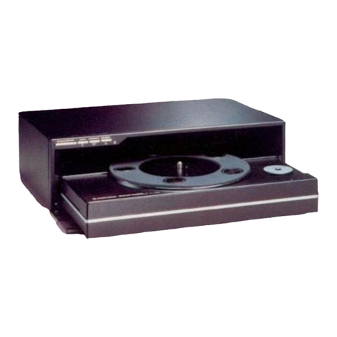
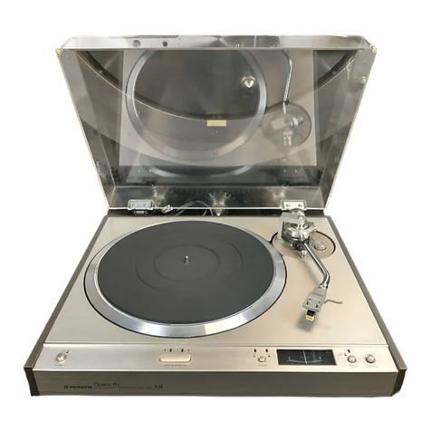
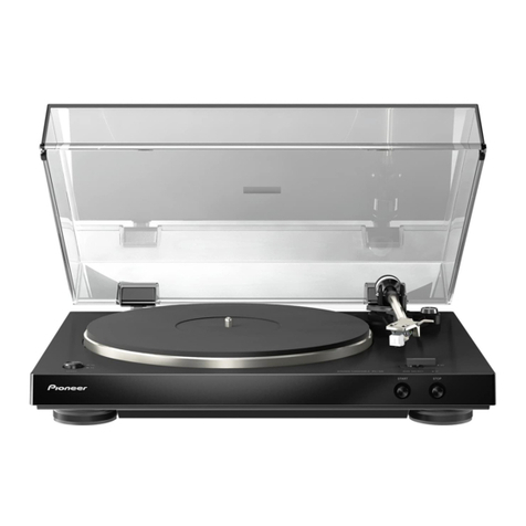
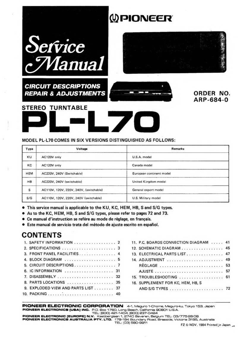
Pioneer PL-630 User manual

Quartz
PLL
DIRECT
DRIVE
FULL
AUTOMATIC
TURNTABLE
L-630
Y
PIONEER’

MODEL
PL-630
COMES
IN
FIVE
VERSIONS
DISTINGUISHED
AS
FOLLOWS:
Type
Voltage
Remarks
KCT
120V
only
Canada
model
(Without
cartridge)
:
KUT
120V
only
U.S.A.
model
(Without
cartridge)
HGT
220V
—
240V
Europe
or
Oceania
model
{Without
cartridge}
ST
110V
—
120V,
220V
—
240V
(Switchable)
General
export
model
(Without
cartridge)
S/G
110V
—
120V,
220V
—
240V
(Switchable)
U.S.
Military
model
(Within
cartridge)
|
=
®
This
service
manual
is
applicable
to
the
PL-630/KCT,
KUT.
For
servicing
of
the
other
types
please
refer
to
the
additional
service
manuals.
CONTENTS
1.
SPECIFICATIONS
..........
0.000
eee
3
7.
DESCRIPTION
OF
OPERATION
2.
PANEL
FACILITIES................000.
4
7.1.
Mechanical
Section
.............004.
29
3.
DISASSEMBLY
............
0.00022
eee
6
7.2.
Control
Section
(Electrical
Section)
......
31
4.
PART
LOCATION
.........
2.000000
0
00s
8
7.3.
Actual
Operation
(17cm
record)
........
34
5.
SCHEMATIC
DIAGRAMS,
P.C.
BOARD
7.4.
Actual
Operation
of
Mechanical
Section
...
35
PATTERNS
AND
PARTS
LIST
©,
ADIUSTMENT
cca
ota
tere
re
tate
eaeh
tee’
36
5.1
Schematic
Diagram
............2.204.
9
9.
D.D.
MOTOR
CIRCUIT
DESCRIPTIONS
5.2
Control
(A)
Assembly
(PWX-035)
.......
11
AND
TROUBLE
SHOOTING
5.3
P.C.
Board
Connection
Diagram.........
12
9.1
Block
Diagram...
2.2...
.
ee
ee
eee
39
5.4
Control
(B)
Assembly
(XWX-007)
.......
15
9.2
Motor
Operation.............
00000.
41
5.5
Switch
Assembly
(XWX-008)
9.3
Operation
of
The
PD1003
IC
and
Lamp
Assembly
(XWX-009)
........
15
(Oscillator
Stage)
..
0...
2.2.0.0.
02
eee
43
5.6
Tonearm
Drive
Assembly
(PWX-027)
.....
16
9.4
Operation
of
The
PA2004
IC
(Comparator
Control)
.........02000.
43
5.7
Power
Supply
Assembly
..............
17
:
9.5
Operation
of
The
PA2005
IC
5.8
Oscillator
Assembly
(PWX-022).........
7
(Drive
Control)
ice
ik
eh
ee
ea
43
5.9
Drive
Control
Assembly
(PWG-017)
.......
18
9.6
Trouble
Shooting
Chart
.............-
48
EXPLODED
VIEW
6.1
Outer
Parts
.........
00.
eee
eee
eee
19
622°
Cabinets
.cs
tec
oe-25
olen
ie
eee
21
6.3.
Tonearm
(Arm
Base)........-..--5055
23
6.4
Under
Base
.....-...
0.00.
eee
25
6.5
D.D.
Motor
(PXM-067)
..............
26
Gi6.
Packingles.dc345Gs
BAR
eA
Senta
e
es
27

1.
SPECIFICATIONS
Motor
and
Turntable
Drive
System.
xs
Gi.
meek
Bak
tee
ates
weer
sae
Direct-drive
MOUOl
seit
da
lahce
olatetineae
lee
earns
naked
Quartz
PLL
Hall
motor
Turntable
Platter........
330mm
diam.
aluminum
alloy
die-cast
Inertial
Mass
.........
340kg-cm2
{including
platter
mat
mass)
SPECS
has,
Seen,
cele
Beare,
Sle
ge
aus
eet
be
eee
33-1/3
and
45rpm
Speed
Control
Range...
6.0.0...
ee
eee
+6%
Wow
and
Flutter................
Less
than
0.025%
(WRMS)
Signal-to-Noise
Ratio.
...........-.
More
than
75dB
(DIN-B)
(with
Pioneer
cartridge
model
PC-600)
Rotational
Characteristics
Build-up
Time
...........
Within
90°
rotation
at
33-1/3
rpm
Speed
Deviation
............0
00002000
Less
than
0.002%
Speed
vs.
Load
Characteristics
.
.
.Stable
up
to
200
grams
drag
load
Speed
Drift
............
Less
than
0.00008%/h
at
33-1/3rpm
Less
than
0.00003%/degree
temp.
change
at
33-1/3rpm
Tonearm
TVPG.
cena
a
dea aes
Whe
Static-balance
type,
S-shaped
pipe
arm
Effective
Arm
Length
............2.....0200005
237mm
Over
angie
ee
eee
oS
Se
dato
wk
Pe
unaoate
Sle
bot
15mm
Usable
Cartridge
Weight...
........
4g
(min.)
to
12.5g
(max.)
(For
cartridge
weights
over
8.5
grams,
attach
the
sub
weight)
Arm
Height
Adjust
Range...
.........
2.00200
0005
+3mm
Subfunctions
Auto
lead-in
Auto-return
Auto
cut
Quick
repeat
Quick
play
Quick
stop
Anti-skating
force
control
Stylus
pressure
direct-readout
counterweight
Arm
height
adjusting
device
Cueing
device
Pitch
meter
Free
stop
hinges
NOTE:
Specifications
and
design
subject
to
possible
modification
without
notice,
due
to
improvements.
PL-630
Semiconductors
LOSiSihei
abe
ded
At
Shr
iat
nets
oN
7
WransisOurs..
eos
syn
Oo
Ses
A
tes
os
te
17
Diodes.
$5.
2i08
eu.
ote
Ae
aieed
ed
hare
bs
9
Hall
Elements
.........
00.0000
00a
ee
3
PED
ids
Giith
2
-walch
eee
dears
che
heats
10
Photo:
Transist6rs.
ccd
Soe
We
es
2
CUS
ove
-s
etki
aes,
Pein
@
Saitek
Meenas
1
Miscellaneous
Power
Requirements
..........
AC
120V
60Hz
Power
Consumption
..............00-
22W
Dimensions
......
470(W)
x
148(H)
x
418(D)mm
18-1/2(W)
x
5-13/16(H)
x
16-7/16(D)
in.
Weight
.........
0000
ee
eee
12kg/26lb
7o0z
Accessories
EPiadaptor:®
sect
af
tt
had
ON
eth
Ace
ts
]
Overhang
gauge
2.0.2.0...
cee
ee
ee
1
Screwdrivers.
cia
3
bocteat
Recast
ks
a
1
Sub
weight:
22
Acscceg
Waka
tgrme
de
Sau
ws
1
Cartridge
mounting
screws
............00.
6
Cartridge
mounting
nuts
.............0.0.
2
Cartridge
mounting
washers
..............
2
Operating
instructions
..
2... 0...
00000
ee
1

2.
PANEL
FACILITIES
ON
......
Press
this
switch
and
the
power
will
come
on.
The
ARM
ELEVATION
switch
in-
dicator
(
¥)
and
SPEED
switch
indicator
(45
or
33)
will
both
light
up.
OFF
....
The
power
will
be
cut
off
when
this
switch
is
released,
and
the
indicators
will
go
off.
NOTES:
e
The
platter
will
not
rotate
when
the
tonearm
is
on
the
arm-rest
even
when
the
POWER
switch
is
set
to
ON.
e
Always
set
the
POWER
switch
to
OFF
when
you
do
not
intend
to
use
your
turntable.
AUTO
SWITCH’
">
ON
......
Select
this
position
for
auto
play
(refer
to
page
10).
When
this
switch
is
pushed,
the
DISC
SIZE
indicator
(12"'30)
lights
up.
OFF......
When
this
switch
is
released,
the
auto
mechanism
is
disengaged,
and
all
the
oper-
ations
can
be
performed
by
hand.
Set
the
switch
to
this
position
when
playing
a
record
whose
size
is
not
standardized
since
the
tonearm
will
otherwise
return
to
the
arm
rest
automatically.
When
this
switch
is
set
to
OFF,
you
will
not
be
able
to
per-
form
auto
play
and
repeat
play
operations.
For
record
play,
move
the
tonearm
manu-
ally.
NOTE:
e
When
the
AUTO
switch
is
set
to
OFF,
the
DISC
SIZE
and
REPEAT
switch
indicators
will
not
light
up
even
if
the
respective
switches
are
pushed.
Press
the
switch
that
corresponds
to
the
size
of
the
record
you
want
to
hear
for
auto
play
operations.
The
corre-
sponding
switch
indicator
will
then
light
up.
N22
307
ee
a
For
30cm
records
10°25
.....
For
25cm
records
7°17.
.....
For
17cm
records
NOTES:
e
The
12''30
switch
is
selected
automatically
when
the
POWER
switch
is
set
to
ON.
©
These
switches
will
not
work
if
depressed
when
the
tonearm
is
moving
(auto
return).
Dust
cover
Platter/
rubber
platter
mat
REPEAT
SWITCH
Press
this
switch
for
repeat
play.
When
pressed,
the
indica-
tor
will
light
up,
and
the
record
will
be
played
again
(refer
to
page
11
for
further
details
on
repeat
play).
Press
this
switch
again
to
release
it.
The
indicator
will
go
off
and
the
repeat
play
function
will
be
released.
NOTES:
e
This
switch
cannot
be
operated
even
if
depressed
while
the
tonearm
is
moving
out
of
contact
with
the
record.
e
There
will
be
no
repeat
play
when
the
AUTO
switch
is
set
to
OFF.
START/STOP
SWITCH
~~
Press
this
switch
for
auto
play.
The
platter
will
start
to
rotate,
the
tonearm
will
automatically
move
over
to
the
edge
of
the
record
and
play
will
begin
(auto
lead-in).
If
this
switch
is
pressed
during
play,
the
tonearm
will
automatically
return
to
the
arm
rest,
the
platter
will
stop
rotating
and
play
will
be
suspended
(auto
cut).
NOTES:
e
This
switch’s
STOP
function
has
no
effect
on
tone-
arm
movement
unless
the
tonearm
is
in
contact
with
the
record.
e
This
switch
cannot
be
selected
when
the
AUTO
switch
ts
set
to
OFF.

y/
o%
\4
(STV
Arm
lifter
[5%
om
Arm
rest
Ge
Anti-skate
knob
———-
Tonearm
SPEED
SWITCH
33.
....
Set
the
switch
to
this
position
when
playing
a
33-1/3rpm
record
such
as
an
LP.
When
it
is
depressed,
the
33
indicator
lights
up,
and
the
platter
rotates
at
a
speed
of
33-1/3rpm.
45
.....
Set
the
switch
to
this
position
when
playing
a
45rpm
record
like
an
EP.
When
it
is
de-
pressed,
the
45
indicator
lights
up,
and
the
platter
rotates
at
a
speed
of
45rpm.
ARM
ELEVATION
SWITCH
Use
this
switch
to
interrupt
play
temporarily
or
to
per-
form
manual
play.
When
the
DOWN
(
©)
indicator
lights
up,
the
tonearm
will
descend
and
when
the
UP
(
¥)
indicator
lights
up,
the
tonearm
will
rise.
These
two
operations
will
be
per-
formed
alternately
every
time
the
switch
is
pressed.
NOTES:
e@
When
the
POWER
switch
is
set
to
ON,
the
tonearm
will
descend
and
the
DOWN
indicator
lights
up.
Always
set
the
switch
to
DOWN
for
auto
play.
When
the
switch
is
at
UP,
the
auto
return
cancelling
mechanism
is
actuated
and
so
there
will
be
no
auto
return
or
auto
cut.
PL-63O0O
PITCH
CONTROL
KNOB
If
this
knob
is
rotated
with
the
Quartz
LOCK
switch
at
OFF,
you
will
be
able
to
increase
or
decrease
the
speed
of
the
platter
in
respect
to
its
rating.
When
the
knob
is
rotated
in
the
‘‘t’’
direction,
the
platter
will
rotate
faster,
and
when
rotated
in
the
‘‘-”
direction,
it
will
rotate
slower
than
its
rating.
The
PITCH
meter
can
be
observed
to
check
the
amount
of
speed
increase
or
decrease
(up
to
6%
in
either
case).
QUARTZ
LOCK
SWITCH
When
this
switch
is
pressed,
the
Quartz
PLL
circuitry
is
actuated
and
the
indicator
will
light
up.
The
switch
is
usually
kept
at
this
position.
The
platter
will
be
accurately
locked
to
the
rotational
speed
corresponding
to
the
position
of
the
SPEED
switch.
When
this
switch
is
released,
the
Quartz
PLL
circuitry
is
disengaged,
the
PITCH
meter
lights
up
and
the
indicator
goes
off.
Set
the
switch
to
this
position
for
instrumental
and
other
performances
in
accordance
with
the
record
OFF.
6:
being
played.
PITCH
METER
When
the
Quartz
LOCK
switch
is
set
to
OFF,
the
PITCH
meter
lamp
will
light
up,
and
the
variation
in
the
rota-
tional
speed
of
the
platter
in
respect
to
its
rating
(33-1/3
or
45rpm)
can
be
read
out
on
the
meter.
ON
-
+
OFF
(ea
Quarez
PITCH
~OCK
CONTROL

3.
DISASSEMBLY
—
ore
Co
hd
Cabinet
and
Arm
Base
shaft.
6.
Lift
the
cabinet
from
the
rear
side.
As
the
cord
.
Remove
the
4
mounting
screws
retaining
the
is
clamped,
remove
the
cabinet
while
releasing
upper
cover.
the
clamp.
Remove
the
AC
mains
connector.
7.
Undo
the
4
screws
retaining
the
arm
base,
and
.
Remove
the
output
cord
connector.
then
remove
the
arm
base.
.
Remove
the
screws
retaining
the
feet.
.
Move
the
arm
to
the
vicinity
of
the
center
#
Upper
cover
retaining
screws
Output
cord
connector
Fig.
1
Arm
base
retaining
screws
Fig.
2

@
Tonearm
1.
Loosen
the
mounting
screws
holding
PU
plates
A
and
B
which
are
fitted
to
the
arm
shaft,
and
remove
the
PU
plates.
2.
Undo
the
2
screws
retaining
the
tone
arm,
and
then
remove
the
tone
arm.
\{—
Arm
base
PL-630

4.
PART
LOCATION
Cabinet
Toneerm
drive
assembly
PYY-022
PWX-027
Main
weight
assembly
PXA-716
<\
~~.
Arm
base
Power
transtormer_&
__
ana
:
PTT-O050
(KUT)
|
Le
c
Pee
ele
)
PNR-083
PTT-057
(KCT)
:
a.
a
|
_
eal
@
eae
:
_
;
=
eae
———
Kno
}
PAD-037
e——_—_—__—-
Tonearm
assembly
PWR-048
(KUT)
!
PPD-576
PWR-049
(KCT)
é
4
©
—--——
Headshell
assembly
Oscillator
assembly
PXA-697
PWX
-022
@
*
Cap
el
PAD-034
__
Knob
PAA-034
Cap
~
PAD-034
Meter
assembly
PAW-002
Cap
Button
PAD-040
PAD-035
Control
panel
PAN-051

RESISTANCE
VALUE
CODES
Code
numbers
of
resistors
used
in
Pioneer
equipment
are
expressed
in
the
following
way:—
Code
number
—————----—->
RD
%
PS
473
J
NL
Baose
cel
Type
of
resistor
|
Power
rating
Shape
(tubuler)
<
Resistance
(code
value)
<————_____--_
Tolerance
<
Low-noise
marking
~«<
Furthermore,
in
the
list
of
parts
found
in
the
Service
Manual,
the
resistance
(code
value)
part
of
the
above
code
number
is
expressed
as
OU0)
or
OOO.
Resistors
included
in
the
Service
Manual
list
of
parts
|
Ex.
RD
%PSOOO
JNL
When
ordering
resistor
components,
first
ascer-
tain
the
actual
resistance
value
from
the
circuit
diagram,
and
then
convert
it
into
code
no.
form
as
shown
in
the
following
examples.
For
further
details
on
code
numbers,
refer
to
“Tuning
Fork”
VOL.
1.
Ex.
1
For
OOOO
Codes
*
General
resistors
O
Oo
C O
Tt
Significant
figures
Multiplier
(10%)
*
Resistors
with
fractional
values
Oe
Ee
i>
Oe
ooOorda
a
ies
aed
|
Significant
figures
Decimal
point
“4
Significant
figures
Decimal
point
Ex.
1
Nominal
resistance
|
Significant
figure
Multiplier
|
Resistance
(2)
(three
figures)
(10x)
value
code
5.1
BIO;
td
aeers
5R10
5.62
BB20
0
Se
5R62
10
WOr
“Gewese
10RO
|
22.5
2
| a
re
22R5
110
110
x10°
1100
1k
i
(1000)
100
x10
1001
1.56k
1
(1560)
156
x10
1561
10k
2
(10000)
100
x10
1002
33.6k
2
(33600)
336
x10
3362
112k
3
(112000)
112
x10
1123
1M
4
(1000000)
100
x10
1004
1.56M
4
(1560000)
156
x10
1564
Ex.
2
For
Codes
*
General
resistors
0
O
0
5
Significant
figures
eT
Multiplier
(10%)
*
Resistors
with
fractional
values
O
C]
CI
r
Significant
figures
ORO
aE
jt
Decimal
point
Ex.
2
Nominal
resistance
|
Significant
figure
Multiplier
|
Resistance
(2)
(two
figures)
(10X)
value
code
0.5
O55
~~
abeaets
OR5
1.5
The.
=e
1RS
1
01
x10°
010
22
22
x10°
220
330
33
x10!
331
1k
2
(1000)
10
x10
102
5.6k
3
(5600)
oP
a0
pee
68k
3
(68000)
68
x10
683
820k
4
(320000)
82
x10
824
1M
5
(1000000)
a0
ac
me
2.2M
5
(2200000)
72
=
225

AND
PARTS
LIS
5.1
SCHEMATIC
DIAGRAM
5.
SCHEMATIC
DIAGRAMS
P.C.
BOARD
PATTERNS
ai
ict
PO6OOI
\c2
PM6OO!
Qio
28c945
22725
ee
ene
Ic3
vec
#
22~28V
7
Qi
28A733
jrov
Qi
28c945
:
O1
vol2zi2
1c3
CONTROL
(8B)
Ass’y
XWX-
007
c2
c
TA78LO20P
0.047
0.047
Br
Ic10
R2I
bk
AN
R32
18k
R22
1K
aad
R23
1k
C19
10/10
QI
280945
Q3
uPC324C
Q5
2Sc945
Q6
2SC945
O10.
($2473
PITCH
Q2
TPSEOSY)
Q3
2SA733
Q4
2S8¢945
Q5
28C945
Q7
2SC945
Q8
2S8C945
cia
22710
F
pag
aig
I
CRO
SWITCH
DRIVER
(F)
Assty
Q9
EE-SME38
D2
1S2473
rn
CONTROL
<
|
1
Ko
vRe
Rig
3-6K(G)
220
an
VRS
ze
6808)
5S
RIS
Oe
Q2
2S8C¢945
Q4
2S8C945
D7
GL-9PR2
D8
GL-9PR2
09
GL-9PR2
MP
|
:
Feed
O°
FL
IES
SWITCH
Ass’y
XWX-
008
bev
LoomA,
LAMP
Ass’y
XWX-009
GL-9PR2
105,6
RG
GND
To
Tonearm
PXA-461
POWER
SUPPLY
Ass’y
PWR
POWER
SWITCH
CONNECTOR
Uj
Pow
Ol
SIRBAIO
(PCX-O10)
03
SIRBAIO
(PCX-OI0)
-
048
Qi
2sc945
Q2
280234
Q3
280234
2av
33V
470/50)
RI
Scam
ca
fe
PDIOO3
OSCILLATOR
Ass’y
PWX-022
DRIVE
CONTROL
Ass’y
PwG-
015.
J
Lci-9Pg2__)
CONTROL
(A)
Assy
PWX
-
035
bas
ibe
Q2!
PA2004
'
Q22
PA2005
ARMATURE
CORE
Ass’y
PTL-003
i
{
|
be
ER
Trantormer
To
Contro!
To
Chassis
To
Top
Panel
Cover
SPEED
DETECTOR
Ass’y
PWX-023
RESISTORS;
IN
OHM
1/4W
45%
TOLERANCE
UNLESS
OTHERWISE
NOTED
kk
MMA
(G)
42%
TOLERANCE
CAPACITORS;
IN
uF
UNLESS
OTHERWISE
NOTED
p;pF
This
is
the
basic
schematic
diagram
but
the
actual
circuit
may
vary
due
to
improvements
in
design.
SWITCHED;
SWI
DISK
SIZE(30cm)
ON
-
OFF
Sw2
DISK:
SIZE(25cm)
ON-
OF
F
SW3
DISK
SIZE(I7em)
ON-OFF.
SW4
PEPEAT
ON-OFF
SW5
START/STOP
ON-OFF
SW6
ARM
ELEVATION
UP-DOWN
SW7
AUTO
—
ON-
OFF
SW8
POWER
ON-OFF
SW9
SPEED
33
1/3-45
(rpm)
SWIO
QUARTZ
ON-
OFF
Miscellaneous
Ff
Part
No.
PWX-027
PWX-035
XWX-007
XWX-008
XWX-009
PWG-017
PWX-022
PTL-003
PWR-049
PWR-048
PTT-057
PTT-050
PSA-002
5.2
CONTRO
Parts
List
of
Ce
Part
No.
PSG-009
CEA
100P
10
GL-9PR2
GL-9PG2
10

3
Pe
ee
ee
ene
DE
ie
eed
>ATTERNS
———<
8
>-
<c¢
>—
<0
>————
KE
—<F
>
=
mer,
4!
n>
<I>
<u>
<K
>
—<t>-
<M
>—
P
3
1
28A733
CONTROL
(B)
Ass’y
XWX-
007
11
280945
———
+
(
vol2i2
c3
3
10.7
Q2
2SC945
ol
Q4
2SC945
R24
O07
GL-9PR2
10k
nigf
DB
G-9PR2
D9
GL-9PR2
C7
47/0
Q3
2SA733
29
4
280945
|
Q5
28¢945
|
a7
28945
|
Qe
2sco4s
Q9
EE-SME3B
D2
1S2473
To
Tonearm
CONTROL
Qt
28c945
Q3
uPC324C
Q5
2sc945
Q6
2SC945
O10
1S2473
PITCH
LAMP
Ass’y
XWX-
009
Ass'y
PWX
-022
ORIVE
CONTROL
Ass’y
PwG-
O15
05,6
L_GL-9P
Pw.
CONTROL
(A)
Ass'y
X-035
ARMATURE
CORE
Ass’y
PTL-003
i
———_.-
4
nn
|
2)c40
4
—
1o7Vv
ves
Q21
PA2004
1orv
epicrse)
RESISTORS,
H
Q22
PA2005
raat
NY.
IN
OHM
1/4W
45%
TOLERANCE
UNLESS
OTHERWISE
NOTED
kik
M;MA
caer’
Are
(G)
42%
TOLERANCE
10735
Jug
cS
001
75
o—O-—©
CAPACITORS;
on
mc3e,
(8
3
IN
uF
UNLESS
OTHERWISE
NOTED
p:pF
16
GS
6
a
-
rs
3
8
er
eens
L
[
2
°
X7R
[33745
87
0.0r
‘|
-_
=
-
Ye
a
10/35
fa
te
HANH
PHE
303F8
C3?
100/35
g
22~
20
Veer
SPEED
DETECTOR
Ass’y
PWX-023
This
is
the
basic
schematic
diagram
but
the
actua!
circuit
may
vary
due
to
improvements
in
design.
SWITCHED;
sw
sw2
sw3
sw4
sw5
swe
Sw7
sws
swo
DISK
SIZE(30cm)
ON
-
OFF
DISK:
SIZE(25cm)
ON
OF
F
DISK
SIZE(I7¢m)
ON-OFF.
PEPEAT
ON-OFF
START/STOP
ON-OFF
ARM
ELEVATION
UP-DOWN
AUTO
ON-OFF
POWER
ON-OFF
SPEED
33
1/3-45
(rpm)
SwiO
QUARTZ
ON
-
OFF
Miscellaneous
Part
Part
No.
PW
X-027
PW
X-035
XW
X-007
XWX-008
XWX-009
PWG-017
PW
X-022
PTL-003
PWR-049
PWR-048
PTT-057
PTT-050
PSA-002
NOTES:
PL-G3O
e
When
ordering
resistors,
first
convert
resistance
values
into
code
form
as
shown.in
the
following
examples.
Ex.
1
When
there
are
2
effective
digits
(any
digit
apart
from
0),
such
as
560
ohm
and
47k
ohm
(tolerance
is
shown
by
J
=
5%,
and
K
=
10%).
5602
56
x
10'
OGD
og
ee
we
RD%PS
BE
47kQ
47x
10°
473
oe,
RD4*PS
AMG
I
0.52
ORS.
52
olds
we
sae
be
eda
RN2H
ORIE)
K
12
ODO
erent
aie
trata
dk
eeY
&
he
RSIP
OOK
Ex.
2
When
there
are
3
effective
digits
(such
as
in
high
precision
metal
film
resis-
tors).
5.62kQ
562
x
10!
DO
2
Tie
2
sie
eget
RN%SR
SIEBAAF
External
Appearances
of
Transistors
Tonearm
drive
assembly
Control
(A)
assembly
Control
(B)
assembly
Switch
assembly
Lamp
assembly
Drive
control
assembly
Oscillator
assembly
Armature
core
assembly
Power
supply
assembly
(KCT)
Power
supply
assembly
(KUT)
Power
transformer
(KCT)
Power
transformer
(KCU)
Power
switch
5.2
CONTROL
(A)
ASSEMBLY
(PWX-035)
28c945
B
2SA733
@e=
Cc
E
2SD234
E
Cc
Cc
B
PA2004
PD1003
PA2005
TPS605
PD6001
13
14
15 16
17
18
19
20
21
22 23 24
7
PM6001
N
N
©
i
&
oe
'
1
Y3g2
a a
1
TA78L020P
3
Parts
List
of
Control
(A)
Assembly
(PWX-035)
Part
No.
PSG-009
CEA
100P
10
GL-9PR2
GL-9PG2
EE-SM3B
Symbol
&
Description
RESO.
xorlich
B9I0INIZI314
C1
St
uPC324
76s!
s!>
|
D1—D4
(without
assembly)
D5,
D6
(without
assembly)
Index
11

5.3.
P.C.
BOARD
CONNECTION
DIAGRAM
TO
CONTROL
PANEL
1
2
TONEARM
DRIVE
ASSEMBLY
(PWX-027)
7
TO
CHASSIS
TRANSFORMERS
CONTROL
(A)
ASSEMBLY
(PWX-035)
~
CONTROL
START
/STOP
POWER
SUPPLY
|;
AC120V
|
60Hz
a)
7
CONNECTOR
o
Sx
POWER
SWITCH
ASSEMBLY
(PWR-048)
ARMATURE
CC
i
|
Ass'y
PTL
GO3
i
CW
IGN
Pol
DRIVER(F)
¢
PXA
461
MICRO
SWITCH
DRIVE
CONTROL
ASSEMBLY
(PWG-017)

TOR
es
BSE
nee
ARMATURE
Cc
Ass'y
PTL
003
oS
AAT
RO
PEE
ORE
RUE
Tee
CONTROL
(A)
ASSEMBLY
(PWX-035)
SWITCH
ASSEMBLY
(XWX-008)
:

PL-630
5.4
CONTROL
(B)
ASSEMBLY
(XWX-007)
are
|
z
|
Q2
2SC945
:
ioe
|
3
3/4
Q4
250945
RIZ
110k
Se
D7
GL-9PR2
righ
DB
GL-9PR2
Lae
DQ
GL-9PR2
Rig
3-6k(G)
Qi
2SC945
aes
a3
474
Q3
uPC324
Q5
2SC945
R22
>
Q6
2SC945
2k
OS
DIO
1$2473
;
24
C8
(NP)
“J
470/6.3
.
O
Os
"I
Parts
List
of
Control
(B)
Assembly
(XWX-007)
SEMICONDUCTORS
Note:
When
ordering
resistors,
convert
the
ae
resistance
value
into
code
form,
and
Fatt
Nee?
=
.<_<
S¥mbel-Se
Description
at
Se
RESISTORS
then
rewrite
the
part
no.
as
before.
oe
ae
int
Part
No.
Symbol
&
Description
28C945-PorQ
=
Q4—06
RD4’VS
COOJ
~—aR1—
RG,
RY,
R12,
R13,
R16—R28
182473
D10
RN%PSOOOG
~~
R7,
R8
GL-OPR2
D7—D9
RD%PS
OOOG
R10,
R11,
R14,
R15
CAPACITORS
RD%VSOOOG
=
R29
PCP-020
or
VR1
Part
No.
Symbol
&
Description
PCP-013
PCP-023
VR2
CEA
4R7P
16
C1
Bap
aed
as
CEA
220P
16
Cc2
PCP-022
or
VR3
CQMA
332K
50
C3
PCP-007
CQMA
103J
50
C4
CSZA
R47M
16
C5,
C6
CSZA
330M
16
C7
CEA
471M6.3NP_
C8
5.5
SWITCH
ASSEMBLY
(XWX-008)
and
LAMP
ASSEMBLY
(XWX-009)
LAMP
ASSEMBLY
{(XWX-009)
Parts
List
of
Switch
Assembly
(XWX-008)
Part
List
of
Lamp
Assembly
(XWX-009)
Part
No.
Symbol
&
Description
Part
No.
Symbol
&
Description
PSG-010
Push
switch
PEL-033
Lamp
PSG-011
Push
switch
15
i
i
'
i
|

5.6
TONEARM
DRIVE
ASSEMBLY
(PWX-027)
10
Ic
|
PD6OOI
{C2
PM6OO!
Qio
2Sc945
ésv
somal
|
a
|~f,
R4
1
30001)
|
C!
\
=o
_————
Nw:
2ev2ev
47
QI
2SA733
Qll
2Sc945
SFICIO
22725
'
D1
vol2i2
1c3
TA78LO20P
+4
2of_c'S*
22710
R32
18k
WA———
+
C19
10/10
Q2
TPSEOS®
Q3
2SA733
Q4
2SC945
Q5
2SC945
Q7
280945
Q8
2SC945
Parts
List
of
Tonearm
Drive
Assembly
(PWX-027)
SEMICONDUCTORS
Part
No.
PD6001
PM6001
TA78LO020P
2SA733P
or
O
TPS605-Y
2SC945-P
or
O
EE-SME3B
PCX-031
VD1212
182473
CAPACITORS
Part
No.
CKDYF
4732
50
CEA
100P
25NP
CEA
220P
10
CSZA
4R7M
10
CEA
220P
25
CSZA
010M
25
16
Symbol
&
Description
1C1
IC2
IC3
Q1,Q3
Q2
Q4,
Q5, Q7,
08,
Q10,
Q11
a9
cds
Di
D2
Symbol
&
Description
C1,
C2,
C8
C3,
C4
C5,
C12,
C13,C11
C7
C10
C14
Q9
EE-SME3B
02
1S2473
Part
No.
CSZA
220M
10
CSZA
100M
10
RESISTORS
Part
No.
RD%VS
000
J
RS1P
OJ
RD%PS
0000
J
RD%“VS
O00
J
PCP-025
(PCP-010)
OTHERS
Part
No.
PEB-123
PKP-020
PEL-025
To
Tonearm
Symbol
&
Description
C15
C16—C20
Note:
When
ordering
resistors,
convert
the
resistance
value
into
code
form,
and
then
rewrite
the
part
no.
as
before.
Symbol
&
Description
R1—R3,
R5,
R6,
R8, RY,
R16—R20,
R22—R28
R4
R7,
R15, R13, R14,
R32,
R21,
R30,
R31,
R33
VR1
Description
Rubber
bush
Connector
5p
Lamp

5.7
POWER
SUPPLY
ASSEMBLY
PWR-048
...
KUT
PWR-049...KCT
oo
Q2,3
280234
276V
PL-630
Saber
es,
ce
cr
0.047A25
Toorvres
ai
2sc945
01,3
SIRBAIO
(PCX-O10)
Parts
List
of
Power
Supply
Assembly
Part
No.
Symbol
&
Description
2SC945-P
or
O
Qi
28D234-0
or
Y
Q2,
Q3
SIRBA10
D1,
D3
WZ-290
D2
WZ-085
D4
RS2P
102J
R1
RS2P
301J
R2
PCL-020
(KCT)
C1
PCL-021
(KUT)
C1
5.8
OSCILLATOR
ASSEMBLY
(PWX-022)
ClO
0.01
9
co}
2
6
a
t
Parts
List
of
Oscillator
Assembly
(PWX-022
)
CAPACITORS
Part
No.
Symbol
&
Description
CCDCH
330/50
C1
CCDCH
560J50
C2
CQMA
562)
50
C3
COSH
472/50
C4
CKDYF
103250
C5,C7—C10
CEA
100P
16
C6
Part
No.
Symbol
&
Description
PCL-019
(KCT)
c2
KCE-005
(KUT)
C2
CKDYF
102Z
50
C3,
C8
(KUT)
CEA
471P
50
C4
CEA
101P
35
C5
CEA
471P
25
C6
CEA
101P
10
C7
CKDYF
473250
C8
(KCT)
PEC-043
Capacitor
cover
Note:
When
ordering
resistors,
convert
the
resistance
value
into
code
form,
and
RESISTORS
then
rewrite
the
part
no.
as
before.
Part
No.
Symbol
&
Description
RD“PS
oJ
R1i—R3
RN%PS
COCG
R4
PCP-015
VR1
10kQ-B
SEMICONDUCTORS
Part
No.
Description
PD1003
IC
PSS-003
Crystal
17

5.9
DRIVE
CONTROL
ASSEMBLY
(PWG-017)
Q21
PA2004
Q22
PA2005
oe
100/35
O
O
=
G
Veel
Parts
List
of
Drive
Control
Assembly
(PWG-017)
CAPACITORS
Note:
When
ordering
resistors,
convert
the
resistance
value
into
code
form,
and
Part
No.
Symbol
&
Description
RESISTORS
then
rewrite
the
part
no.
as
before.
CEA
101M6.3NP
C21
Part
No.
Symbol
&
Description
CKDYF
403Z50
C22
CKDYB
681K
50
C23
PCP-019
VR21,
VR22
15kQ-B
CQMA
154J
50
C25
COMA
104/50
‘C26,
C30
RD%PS
J
-
R21—R30,
R32—R35
RD%PS
D000
J
R31
CQMA
153/50
C27
RS1P
J
R36
CSZA
R47K
35
C28
COMA
TOM
BO
G20
SEMICONDUCTORS
CEAO1OM50NP_
C31
0
CQMA
563K
50
C33
Part
No.
Symbol
&
Description
CEA
010P50
C34
PA2004
Q21
CSZA
R33K
35
C35
PA2005
Q22
CSZA
100K
16
C36
PCX-039
HA,
HB,
HC.
Hall
element
CEA
101P
35
C37
PTL-003
Armature
core
assembly
CEA
100P
35
C38,
C39,
C40
CKDYF
103Z50
C41
18
Pee
Sn

PL-G3O
6.
EXPLODED
VIEW
NOTE:
{_)
marked
parts
cannot
be
supplied.
6.1
OUTER
PARTS
Dust
cover
PNV-024
Hinge
assembly
PXA-380
Plate
PNB-105_
OCW
4x8
Rubber
mat
assembly
PEA-035
(KUT)
PEA-036
(KCT)
PSB
3x8
Turntable
pilater
PNR-084
AA
Screw
\
a
PBA-080
~
PSA
4x8
20

6.2
CABINET
NOTE:
[L___]
marked
parts
cannot
be
supplied.
Switch
assembly
XWX-008
1
Plate-R
Push
switch
PSG-011
PT
2.6x6
PNW-324
Push
switch
PSG-010
Cap
PAD-040
PT
2.6x6
Lamp
assembly
XWX-009
Cover
Lane
see
PNW-435
PEL-033
Meter
assembly
PAW-002
Variable
resistor
PCS-012
Knob
Control
(A)
assembly
PYY-022
Eee
yy
PWX-035
Cc
Z
z
Rubber
bush
dates
ap
PEB-114
Nuk
ADP
3x6
PAD-033
Screw
PBA-080
PSB 3x8
a
*
,
[Plate
|
PSB
3x8
mew
Output
cord
assembly
PDX-006
(KUT)
PDX-003
(KCT)
Button
_
ky
crew
PAD-035:
Push
switch
PBA-030
PSG-013
Baworawitch
AC
power
cord
assembly
PSA-002
PDF-097
Control
panel
SS
Screw
;
p
PAN-051
SS
TG
PBA-030
8d)
PAD-034
(Include
Collar
PNW-450
SAWN
g
21

1
6.3
TONEARM
(ARM
BASE)
:
Mechanism
assembly
PXA-461
PL-GS3SO
NOTE:
(1
marked
parts
cannot
be
supplied.
H
Belt
PEB-097
PSF-005
Frame
Microswitch—
76,
PT
2x10
ADP
3x6
Motor
pulley
PNW-392
Motor
PXM-059
[Stonner}
2
!
PSF-005
of
ee
Microswitch
ce
PSA
2.6x5
-
EW
2.5
Washer
PU
adjust
cam
—&S
@——
N5
in
PXT-243
Rubber
ring
pied
PEB-122
Plate
spring
PBK-023
Spring
nS
PBH-176
y
Plate
PNC-040
4
Fi
;
Plate
@——[Rubber,
er
wd
~
PNW-431
Stopper
PNW-469
Spring
PBH-151
Screw
“Lever
ame
PNB-460
RT
3x6—
Cam
i
E
Screw
PBA-071
Lever
PNB-461
‘
6
——
Fw3
Tonearm
drive
assembly
PWX-027
PNW-379
I)
Washer
i
Washer
ig
PBE-012
Spring
PBH-166-——g
.
J
RT
3x6
Knob
Washer
|
PBF-008
PSB
4x10
Arm
base
PNR-083
a
PS
ora
PAD-037
Rubber
bushj——_—&
~N
PEB-123
i
|
Lamp
PEL-025
Photo
cupler
EE-SME3B
gt
SO
ae
ee
2
eee
en
ee
a
el
Rubber
bush
PEB-114
PLA-358
Arm
rest
PXA-500
Shaft
holder
4
PNW-448
Cp
Shaft
PLA-356
SF
2.6
x
eae
EV
sheet
assembl
PXA-469
Tonearm
assembly
PPD-576
24
ee
ed
Slee
See
Cle
a
Table of contents
Other Pioneer Turntable manuals

Pioneer
Pioneer DEH-2790MP User manual

Pioneer
Pioneer PL-51A User manual

Pioneer
Pioneer BDP-170 User manual

Pioneer
Pioneer CDJ-2000NXS User manual

Pioneer
Pioneer PL-560 User manual

Pioneer
Pioneer PL-51 User manual

Pioneer
Pioneer PL-600 User manual

Pioneer
Pioneer XDJ-1000 User manual

Pioneer
Pioneer DEH-P7550MP User manual
Pioneer
Pioneer PL-50 User manual

Pioneer
Pioneer pl-510 KLT User manual

Pioneer
Pioneer PL-530 User manual

Pioneer
Pioneer PL-225 User manual

Pioneer
Pioneer PL-600 User manual

Pioneer
Pioneer DC-Z93 User manual

Pioneer
Pioneer PL-470 User manual

Pioneer
Pioneer PL-05 User manual

Pioneer
Pioneer DEH-P6500 User manual

Pioneer
Pioneer PL-L70 User manual

Pioneer
Pioneer pl-x50 User manual