Operating
Instructions
STEREO
TURNTABLE
L-L.7O
Thank
you
for
buying
this
Pioneer
product.
Please
read
through
these
operating
instructions
and
then
you
will
know
how
to
operate
your
model
properly.
After
you
have
finished
reading
the
instructions,
put
them
away
in
a
safe
place
for
future
reference.
In
accordance
with
the
power
and
voltage
requirements
of
dif-
fering
areas,
the
following
model
names
are
used
to
designate
models
with
differing
electrical
specifications.
Line
voltage
HEM,
HB,
a.c.
220,
240
valts
©
(Switchable
voltage}
INEZ
a
:
Beret
20-240
volts
~
S,$/G,
SS
|
AC
110,
120,
220,
240
volts
(Switchable
voltage)
Ip,
D/G
AC
120,
220,
240
volts
{Switchable
voltage)
R,
RIG
meet
"AC
1
10120,
220~240
volts
(Switchable
voltage!
|
Ku,Ko)
[AC
10vols
YP,
YB
6.
240
volts
~~
"|
NOTES:
*
The
model
names
are
stamped
an
the
packing
case.
°
These
operating
instructions
are
prepared
on
the
basis
of
the
HEM
model,
and
they
can
be
used
for
other
models.
Although
the
design
of
the
power
plug
and
the
power
outlet
shown
may
differ
from
the
actual
one,
the
operating
procedures
are
the
same.
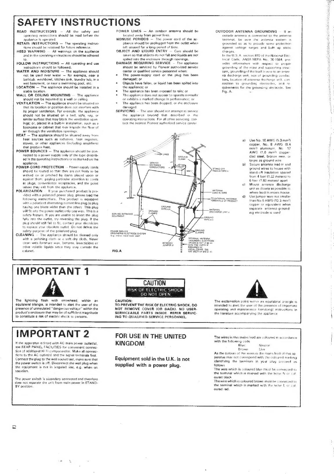
WARNING:
to
prevent
eine
OR
SHOCK
HAZARD,
DO
NOT
EXPOSE
THIS
APPLIANCE
TO
RAIN
OR
MOISTURE.
Panel
Facilities
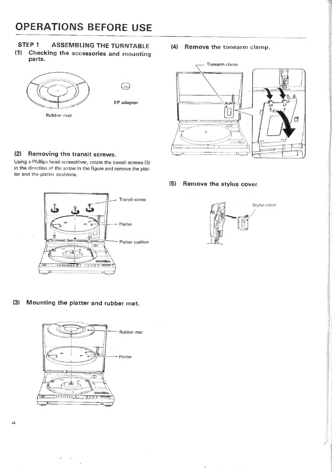
Operations
before
Use
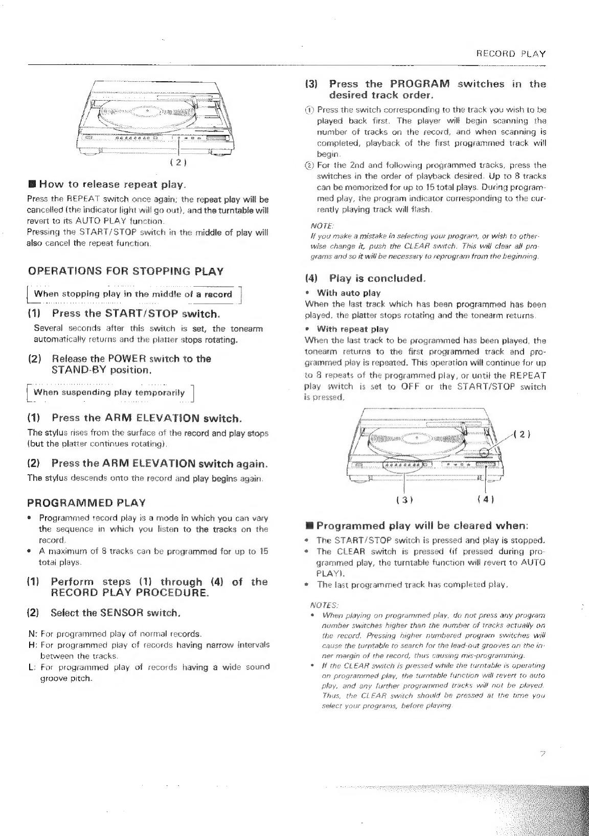
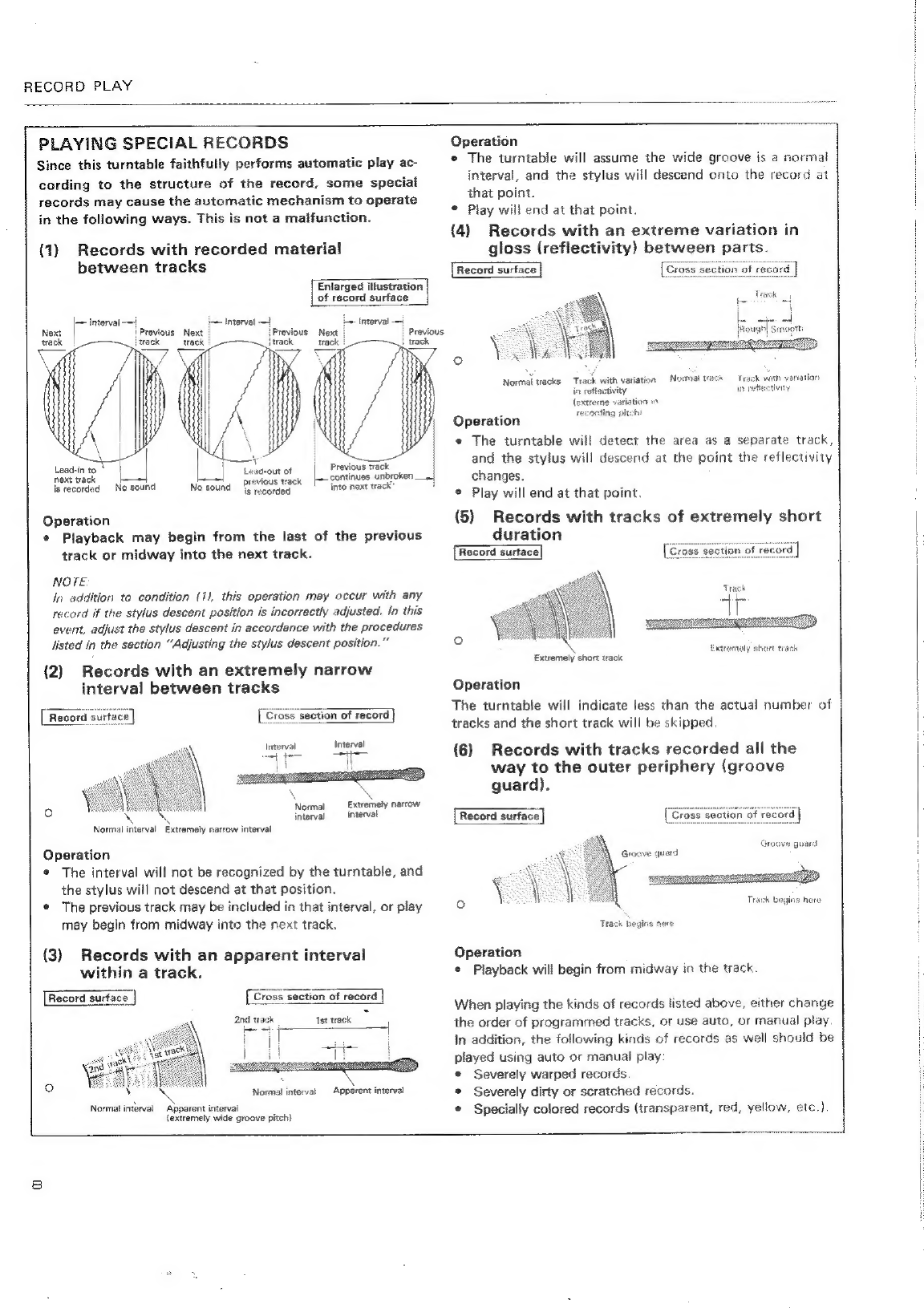
R&GOrE
Play:
sisicactcnrmamivenearenennneeaie
ecveetnelic
ee
EAT
i
________CONTENTS___
Ru,
LINE
VOLTAGE
SELECTOR
SWITCH
[only
multi
voltage
models
are
provided
with
this
switch
but
U.S.A,
and
Canada
models
are
not
pro-
vided
with
this
switch]
The
line
voltage
selector
switch
is
located
on
the
top
of
the
cabinet
of
this
turntable.
Before
your
turntable
is
shipped
from
the
factory,
the
switch
is
set
to
the
power
requirements
of
the
turntable’s
destination.
Check
that
it
is
set
properly
before
plugging
the
power
cord
into
the
outlet.
If
the
voltage
is
not
properly
set
or
if
you
move
to
an
area
where
the
voltage
re-
quirements
differ,
adjust
the
selector
switch
as
follows:
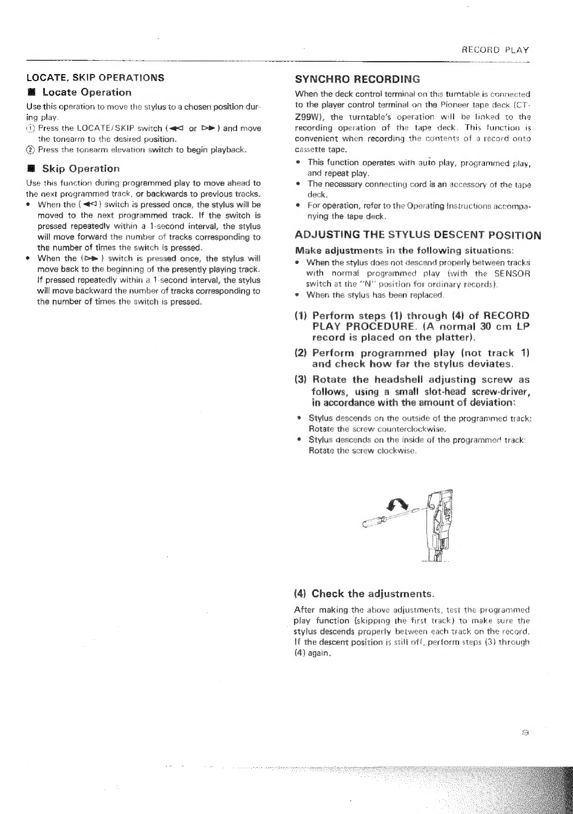
e
Provide
yourself
with
a
medium-sized
screwdriver,
Insert
the
tip
of
the
screwdriver
into
the
groove
of
the
selector
switch
and
turn
it
so
that
the
power
voltage
marking
of
your
area
points
to
the
arrow.
a
IMPORTANT
NOTICE
[For
U.S.A,
and
Canada
models]
The
serial
number
for
this
equipment
is
located
on
the
rear
panel.
Please
write
this
serial
number
on
your
enclosed
war-
ranty
card
and
keep
in
a
secure
area.
This
is
for
your
security.
Maintenance
...
Specifications
.
TOUbEShOStIN”
-wenessedemewerareetickens
12
Y)
PIONEER’