D200-13-00 2 I56-0305-010R
© System Sensor 1998
Three-Year Limited Warranty
System Sensor warrants its enclosed sounder/strobe to be free from
defects in materials and workmanship under normal use and service for a
period of three years from date of manufacture. System Sensor makes no
other express warranty for this sounder/strobe. No agent, representative,
dealer, or employee of the Company has the authority to increase or alter
the obligations or limitations of this Warranty. The Company’s obligation
of this Warranty shall be limited to the repair or replacement of any part
of the sounder/strobe which is found to be defective in materials or work-
manship under normal use and service during the three year period com-
mencing with the date of manufacture. After phoning System Sensor’s toll
free number 800-SENSOR2 (736-7672) for a Return Authorization number,
send defective units postage prepaid to: System Sensor, Repair
Department, RA #__________, 3825 Ohio Avenue, St. Charles, IL 60174.
Please include a note describing the malfunction and suspected cause of
failure. The Company shall not be obligated to repair or replace units
which are found to be defective because of damage, unreasonable use,
modifications, or alterations occurring after the date of manufacture. In no
case shall the Company be liable for any consequential or incidental dam-
ages for breach of this or any other Warranty, expressed or implied what-
soever, even if the loss or damage is caused by the Company’s negligence
or fault. Some states do not allow the exclusion or limitation of incidental
or consequential damages, so the above limitation or exclusion may not
apply to you. This Warranty gives you specific legal rights, and you may
also have other rights which vary from state to state.
System Sensor’s sounder and signal strobe is designed to provide fire and
security hazard warning.
The strobe is for supplementary signaling use only.
The sounder or sounder/strobe combination will not work without
power. The sounder or sounder/strobe gets its power from the fire or
security panel monitoring the alarm system. If power is cut off for any rea-
son, the sounder or sounder/strobe combination will not provide the
desired audible or visual warning.
The sounder may not be heard. The loudness of the sounder meets or
exceeds current Underwriters Laboratories’standards. however, the
sounder may not alert a sound sleeper or one who has recently used drugs
or has been drinking alcoholic beverages. The sounder may not be heard
if it is placed in an area which is isolated by a closed door, or if it is locat-
ed on a different floor from the person in hazard or if placed too far away
to be heard over the ambient noise such as traffic, air conditioners,
machinery, or music appliances that may prevent alert persons from hear-
ing the alarm. The sounder may not be heard by persons who are hear-
ing impaired.
The signal strobe may not be seen. The electronic visual warning signal
meets or exceeds current Underwriters Laboratories’standard 1638. The
visual warning signal is suitable for direct viewing and must be installed
within an area where it can be seen by building occupants. The strobe
must not be installed in direct sunlight or areas of high light intensity
where the visual flash might be disregarded or not seen. The strobe may
not be seen by the visually impaired.
The signal strobe may cause seizures. Individuals who have a positive
photic response to visual stimuli with seizures, such as epileptics, should
avoid prolonged exposure to environments in which strobe signals,
including this strobe, are activated.
The Limitations of Sounders and Strobes
Mounting
PA400 Sounders
1. The PA400 is intended for mounting to a standard 2-1/2"deep
single-gang box which allows sufficient clearance for conduit
entrance.
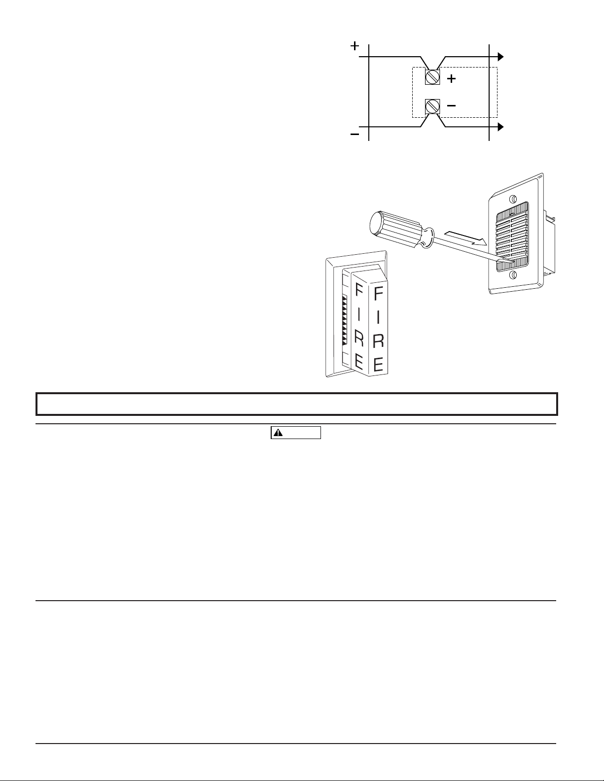
2. The PA400 is compatible with DC line supervision. The Piezo
Alert is polarized and has terminals marked with polarity.
Apply positive supply voltage to the (+) terminal and negative
supply voltage to the (–) terminal. (See Figure 5.)
3. Mount the appliance to the electrical outlet box using the two
mounting screws supplied.
4. Field repair of the PA400 should not be attempted. Return to
factory for repair or replacement.
PS12 or PS24 Strobes
These optional strobes are interconnected to the PA400 by first
removing the two mounting screws from the sounder. Use a small
screwdriver to punch out the skinned-over areas as indicated in
Figure 6. Install the adapter plate on top of the sounder and screw
the combined sounder and adapter plate to the electrical outlet
box. Make sure field wiring terminals are oriented in the upward
position when mounted in the outlet box. Next, slide the strobe
directly into the slots in the plates. The positive solder lug may be
colored red or marked with a plus sign (+). This lug must be in
the slot closest to the field wiring terminals. Grasp the catch area
on each end of the strobe and squeeze while applying inward
force. Make sure the strobe catches fully engage the slots in the
adapter plate and that no gap appears at the interface between the
strobe and adapter plate.