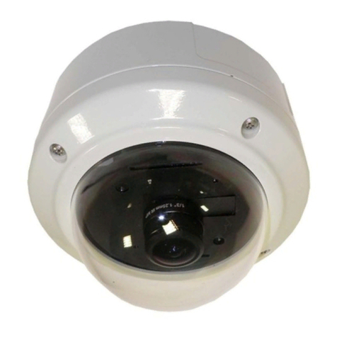
PiXORD PD736 User manual

P
PP
PD736 5
D736 5D736 5
D736 5MP
Dome Type
Dome TypeDome Type
Dome Type
Panorama
PanoramaPanorama
Panorama
Network Camera
Network CameraNetwork Camera
Network Camera
User’s Manual
Version 2.01
February 2014


Trademark Acknowledgments:
PiXORD is a registered trademark of PiXORD Corporation.
All other trademarks used in this handbook are registered trademarks of their respective
companies.
Copyright © 2014 by PiXORD Corporation
All Rights Reserved
Printed in Taiwan
PiXORD Corporation reserves the right to make corrections, modifications, enhancements, improvements, and
other changes to its products and services at any time and to discontinue any product or service without notice.
Customers should obtain the latest relevant information before placing orders and should verify that such
information is current and complete. All products are sold subject to PiXORD Corporation’s terms and conditions
of sale supplied at the time of order acknowledgment.
PiXORD is not responsible or liable for the resale of its products with statements different from or beyond the
specification/parameters stated by PiXORD. Customers are responsible for their applications using PiXORD
products. To minimize the risks associated with customer applications, customers should provide adequate
operating safeguards. PiXORD is under no obligation to provide any further technical support service or
product/software alteration beyond PiXORD's representation.
PiXORD products are not authorized for use in safety-critical applications where a failure of the PiXORD product
would cause severe personal injury or death, unless officers of the parties have executed an agreement specifically
governing such use.
Reproduction of PiXORD information or datasheets with alteration is prohibited. PiXORD is not responsible or
liable for any of such altered statements.
Every care has been taken in editing this manual. If there are any inaccuracies or omissions, please inform your local
PiXORD office. PiXORD Corporation cannot be held responsible for any typographical or technical errors.
PiXORD Corporation is not liable or responsible for incidental or damages caused by any misinterpretation of this
publication.
PiXORD Corporation
6F, 12 Innovation 1st Road
Hsinchu Science Park
Hsinchu, TAIWAN 30076
Tel:+886 3 567-8818
Fax:+886 3 567-8990
marketing@pixord.com


Contents
PD736 User’s Manual iii
Contents
ContentsContents
Contents
Contents
ContentsContents
Contents
iii
iiiiii
iii
Important Notes ........................................................................................................... vii
Customer Support ........................................................................................................viii
1
11
1 Introduction
IntroductionIntroduction
Introduction
1
11
1
Hardware Overview........................................................................................................ 2
2
22
2 Installation and Setup
Installation and SetupInstallation and Setup
Installation and Setup
5
55
5
2.1 Camera’s Mounting Bracket Installation................................................................... 5
2.2 Connecting Camera to Network through LAN Router Cable.................................... 6
2.3 Configuring and Finding Camera via Software ......................................................... 7
2.3.1 Open the Web-based UI ........................................................................... 12
3 Camera Live View UI Sett
3 Camera Live View UI Sett3 Camera Live View UI Sett
3 Camera Live View UI Settings
ingsings
ings
14
1414
14
3.1 Quick Access Buttons ........................................................................................... 16
3.2 Camera Live View UI Setting Tools ...................................................................... 17
4
44
4 Setup Execution
Setup ExecutionSetup Execution
Setup Execution
22
2222
22
4.1 System Setup Execution........................................................................................ 22
4.1.1 Information Tab ....................................................................................... 23
4.1.2 Time Tab.................................................................................................. 24
4.1.3 Security Tab............................................................................................. 25
4.1.4 Maintenance Tab...................................................................................... 27
4.1.5 System Log Tab ....................................................................................... 29
4.2 Network Setup Execution..................................................................................... 30
4.2.1 General Tab.............................................................................................. 30
4.2.2 Wireless Tab (*Optional function) ............................................................ 32
4.2.3 DDNS Tab............................................................................................... 33
4.2.4 Multicast Tab ........................................................................................... 34
4.2.5 IP Filter Tab............................................................................................. 35
4.3 Video & Audio Setup Execution ........................................................................... 36
4.3.1 Stream Tab............................................................................................... 37
4.3.2 Video Tab ................................................................................................ 39
4.3.3 Audio Tab................................................................................................ 46
4.3.4 Privacy Mask Tab..................................................................................... 47
4.4 Event Setup Execution.......................................................................................... 49
4.4.1 Motion Tab .............................................................................................. 49
4.4.2 Video Tab ................................................................................................ 51
4.4.3 Snapshot Tab ........................................................................................... 55

Revision History
iv PD736 User’s Manual
4.5 Local Storage Setup Execution ............................................................................. 60
4.5.1 Local Storage Tab.................................................................................... 60
4.5.2 Playback Tab............................................................................................ 61
4.6 Remote Storage Setup Execution.......................................................................... 62
4.6.1 Remote Storage Tab................................................................................. 62

Contents
PD736 User’s Manual v
Revision History
Doc.
Version Revision Description Date
2.0 Add more functional descriptions 2014/02/24
1.0 Initial Official Release 2013/08/30


Read Me First!
PD736 User’s Manual vii
ead Me First!
Important Notes
This User Manual is intended for administrators and users of the PD736 Network
Dome Camera, including instructions for using and managing the camera on your
network. The use of surveillance devices may be prohibited by law in your
country or area. It is therefore the user’s responsibility to ensure that the
operation of such devices is legal before installing this unit for its intended use.
Before the Network Dome Camera is installed, carefully read and follow all the
safety and operating instructions to avoid damage due to faulty assembly and
installation. This also ensures that the device is used properly as intended.
Heed All Warnings
Do not drop or hit the device.
Sensitive electronics inside the camera are vulnerable to excessive impact.
Do not install the device under high temperature (less than 45°
°°
°C)
environment.
Excessive heat could damage the equipment.
Do not cover device with any object or install it in a poorly ventilated
vicinity.
Overheating could damage the camera.
Do not expose the device to rain or moisture. Do not touch the power
connection with wet hand.
Risk of short circuit, electric shock, or fire
Do not damage the power cord or leave it under pressure.
Risk of fire or circuit electric shock
To reduce the risk of electric shock or damage, do not remove the front
or back cover.
There is no user-serviceable parts inside. Misusage, improper, or negligent
handling could damage the device. Refer to qualified service personnel from
PiXORD distibutor/dealer for any device related trouble shooting need.

Read Me First!
viii PD736 User’s Manual
Do not continue to operate the device if it appears to malfuntion.
Contact qualified service personnel from PiXORD distibutor/dealer for help.
Installation of the product should be made by qualified service personnel
or system installers from PiXORD distibutor/dealer.
Customer Support
If you require any technical assistance, please contact your nearest PiXORD
distributor/dealer. You may also access the PiXORD website at
www.pixord.com for following supports:
Find answers to resolved your problems from FAQ database or contact our
FAE at technical support (http://www.pixord.com/contact2.asp).
Download latest user documentation and firmware updates at PiXORD
Support (http://www.pixord.com/support/support.asp)
Registration
To receive the latest updates of product information in the future, register your
equipment at http://register.pixord.com/register/.

Chapter 1
PD736 User’s Manual Introduction
•
••
•1
1
11
1
Introduction
IntroductionIntroduction
Introduction
PD736 is a Fish-Eye Panorama Network Dome Camera featured with 5Mega
Pixel resolution and superior H.264-AVC performance and rich functions.
PD736 includes a fish-eye lens for 360° panoramic wide angle view without blind
spot. It is very suitable to view a wide area with single camera such as hallway,
store, and office without the need to install multiple cameras.
The hardware base panorama video processing ability provides user flexible
video layout including Panorama, Original View, Double Broad View, Triple
View and Quad View. The e-PTZ function, including preset point without
moving parts, can replace part of traditional PTZ camera and thus save lost of
traditional mechanical Pan/Tilt maintain cost.
The PoE function (PD736E) and Wireless function (PD736W) are designed for
flexible installation.
Further functions include two-way audio, DI/DO alarm application and micro
SD card support for local storage application.

Chapter 1
2 •
••
•Introduction PD736 User’s Manual
Hardware Overview
Interface Description
Light Sensor The Light sensor is for detecting IP Camera environmental
illumination, and if IP Camera was in the dark/night
environment, IR Cut Filter is switched off to let infrared
light pass through for clear night view.
MIC The IP Camera has built-in an internal microphone, which is
hidden in the pinhole located on the front panel.
Lens Focus Adjustment Rotate the lens to adjust the focal length to the best image.
If necessary, clean the lens with a soft cotton cloth.
Speaker The IP Camera has built-in an internal speaker, which is
hidden in the pinhole located on the front panel.
Reset Button This button is hidden in the pinhole.
Insert a pin into the reset hole to press the reset button and
keep pressed about 3 seconds until PWR LED start
refreshing with orange color.

Chapter 1
PD736 User’s Manual 3 •
••
•Introduction
Interface Contents
Power Jack The input power is DC 12V.
Note: ONLY use power adapter supplied with the package.
Otherwise, the product may be damaged.
RJ-45 LAN Socket Connect to PC or Hub / Switch.
For connect to 10Base-T Ethernet or 100Base-TX Fast Ethernet
Cabling. This Ethernet port built audio-negotiation protocol which
can detect or negotiate the transmission speed of the network
automatically.
Please use CAT-5 or above cable to connect the Network Camera to
a 100Mbps Fast Ethernet network switch or hub.
Note: ONLY use one power source, either from DC or from
802.3af Power over Ethernet.
MicroSD Card slot The IP Camera has built-in a MicroSD card slot which can accepts
MicroSD memory card for image / video event recording.
Audio In Connect a microphone to the IP Camera, be noted to use actively
microphone (normally with power supplier on microphone) for this
application.
Audio Out Connect a loud speaker to the IP Camera.
This is for voice alerting and two-way audio. Be noted to use
actively speaker (normally with power supplier on speaker) for this
application.
GPIO The 7 pin terminal block includes 1 input port and 2 output ports.
Pin Function Description
1 GND Digital Input: only one set is designed
in this Camera Model. The internal
device is also photo-coupled electrical
relay; and the external device can be
simply an On/Off switch. Each set of
On/Off switch can be connected as one
trigger source.
2 DI
3 GND
4 DO_COM
5 DO_NO2
6 DO_COM
7 DO_NO1

Chapter 1
4 •
••
•Introduction PD736 User’s Manual
Digital Output: each digital output pin
to COM is a photo-coupled relay on
Normal Open status. External device
can directly connect to the terminals.
However the current that will go
through the 2 nodes must not exceed
130mA. An external “Relay” can also
be connected to the terminals as an
implementation. In this case, current
(or/and voltage) limitation is specified
by the external Relay.

Chapter 2
PD736 User’s Manual Installation and Setup
•
••
•5
2
22
2
In
InIn
Installatio
stallatiostallatio
stallation
nn
n
and Setup
and Setupand Setup
and Setup
2.1 Camera’s Mounting Bracket Installation
Please attach the supplied alignment sticker to the place you would like to set up
first. And then follow the drilling and installing instructions on the sticker to
complete Camera’s installation.
Figure 2-1 Mounting bracket installation
NOTE
Always mount the Camera on mounting bracket to prevent over heating.

Chapter 2
6 •
••
•Installation and Setup PD736 User’s Manual
2.2 Connecting Camera to Network through LAN
Router Cable
Figure 2-2 Connecting IP Camera to Network
1. Prepare a PC/notebook/ultrabook with Ethernet link to the network.
2. When PC/notebook is used, connect the LAN port of the device to the network router
with an RJ45 network cable (1
11
12
22
2).
3. Plug the DC power jack of the power adaptor (3
33
34
44
4) to Camera and connect the
power adaptor to power outlet (110V or 220V).
4. Connect the network router to the LAN port of Camera with an RJ45 network cable
(5
55
5).
5. With power switched on, check the status of the two LEDs at the back of camera:
LAN Router
Power Adapter

Chapter 2
PD736 User’s Manual 7 •
••
•Installation and Setup
If the Network LED flashes with green color, it confirms that the Camera has
successfully linked with the Internet.
Figure 2-3 Network (Right LED) Indicators
2.3 Configuring and Finding Camera via Software
You could find CAM FINDER utility from the attached Software Package CD.
The CAM FINDER is used to find and configure network cameras on the LAN.
This utility is useful for conveniently configuring the network settings of the
device, or for finding a device once the network settings have been modified.
To install the CAM FINDER, from the Software Package CD, select CAM
FINDER, then follow the instructions to complete the installation.
NOTE
1. In order to ensure CAM FINDER utility has the best compatibility with Camera,
kindly please goes to the PIXORD website for the latest version downloading.
2. In order to ensure Camera will be assigned IP Address properly, please confirm
the following things.
Always consult your network administrator in order to avoid using a
previously assigned IP address.
Check if the Camera is powered on and correctly connected to the network.
In order to connect to the Web-based user interface of the camera, the host
PC must be in the same subnet. For more information about subnets, please
consult your network administrator.
Network LED should blink with green color
to indicate successful link to the Internet

Chapter 2
8 •
••
•Installation and Setup PD736 User’s Manual
1. Once CAM FINDER has been successfully installed on the PC/notebook/ultrabook,
double click Mouse left button or choose “Start>
>>
>All Programs>
>>
>PIXORD>
>>
>
CAM FINDER” path to run the software.
2. Click the [Device Search] to search the device in the LAN.
Figure 2-4 Find the Camera Device via “Device Search” button
3. Under your selected item, double-click the left Mouse button or Right-click the
Mouse button to open the Property Page item [Single Device Setting].
Figure 2-5 Open the Camera’s Property setting page via “Single Device Setting” item

Chapter 2
PD736 User’s Manual 9 •
••
•Installation and Setup
4. Check [Static IP address] or [Use DHCP Service] item to select the network
connection method of the camera.
Figure 2-6 Enter the Camera Device’s network setting manually.
Figure 2-7 Check “Use DHCP Service” item to let camera get IP Address automatically.

Chapter 2
10 •
••
•Installation and Setup PD736 User’s Manual
5. After modifying the camera properties, click [Set] button to save and enable the
configuration modifications.
Figure 2-8 Click “Set” button to save and enable the modification.
Table of contents
Other PiXORD Security Camera manuals

PiXORD
PiXORD P-423 User manual

PiXORD
PiXORD P-465 User manual

PiXORD
PiXORD P-600 User manual

PiXORD
PiXORD PD637 User manual

PiXORD
PiXORD P606 User manual

PiXORD
PiXORD PB731P User manual

PiXORD
PiXORD PD771 User manual

PiXORD
PiXORD PS760D User manual

PiXORD
PiXORD PD636 User manual

PiXORD
PiXORD PL621 User manual

PiXORD
PiXORD PD736 5MP User manual

PiXORD
PiXORD 261 series User manual

PiXORD
PiXORD PB670 User manual

PiXORD
PiXORD PL721 User manual

PiXORD
PiXORD H.264 Series User manual

PiXORD
PiXORD PD737 User manual

PiXORD
PiXORD P-505 User manual

PiXORD
PiXORD P-463 User manual

PiXORD
PiXORD PD636 User manual

PiXORD
PiXORD P-600 User manual