Poettinger TOP 842 C User manual

Operator‘s manual
GB
+ INSTRUCTIONS FOR PRODUCT DELIVERY . . . Page 3
"Translation of the original Operating Manual" Nr. 99 2740.GB.80Q.0
• Double Rotary Swather
TOP 842 C
(Type SK 2740 : + . . 00001)
TOP 962 C
(Type SK 2741 : + . . 00001)

1500_GB-PAGE 2
Product liability, information obligation
Product liability obliges manufacturers and dealers to issue operating instructions for the machine at the point of sale and to instruct
the customer on the operation, safety and maintenance regulations governing the machine.
A confirmation is required to verify that the machine and operating instructions have been handed over correctly.
For this purpose
- Document A is to be signed and returned to Pöttinger or via the internet to www.poettinger.at
- Document B remains with the specialist dealer handing over the machine.
- The customer receives document C.
For the purposes of product liability law, every farmer is an entrepreneur.
In the terms of product liability law, damage to property is any damage arising due to the machine, but not to the machine, and an
excess (500 euros) exists for this liability.
Corporate damage to property within the terms of the product liability law is excluded from this liability.
Be advised! The operating instructions must also be handed over with any subsequent machine sale or transfer and the transferee
must be instructed in the regulations stated.
Pöttinger - Trust creates AfÀnity - since 1871
"Quality pays for itself." Therefore we apply the highest quality standards to our products which are constantly monitored by our
in-house quality management and our management board. Because the safety, perfect function, highest quality and absolute
reliability of our machines in operation are the core competencies for which we stand.
There may be deviations between these instructions and the product as we are constantly developing our products. Therefore no
claims may be derived from the data, illustrations and descriptions. Please contact your Specialist Service Centre for any binding
information about specific features of your machine.
We would ask you to please understand that changes to the scope of supply with regard to form, equipment and technical
specifications are possible at any time.
Any form of reprint, translation or reproduction, including excerpts, requires the written approval of Pöttinger Landtechnik GmbH.
All rights according to copyright laws remain expressly reserved by Pöttinger Landtechnik GmbH.
© Pöttinger Landtechnik GmbH – 31st October 2012
Refer to PÖTPRO for additional information about your machine:
Are you looking for suitable accessories for your machine? No problem! All the information you require is here at your disposal.
Scan the QR code on the machine's type plate or look under www.poettinger.at/poetpro
And if we don't have what your looking for, then your Specialist Service Centre is there for you with help and advice.

Dokument D
GB-0600 Dokum D Anbaugeräte - 3 -
PÖTTINGER Landtechnik GmbH
Industriegelände 1
A-4710 Grieskirchen
Tel. 07248 / 600 -0
Telefax 07248 / 600-2511
TMachine checked according to delivery note. All attached parts removed. All safety equipment, drive shaft and operating
devices at hand.
TOperation and maintenance of machine and/or implement according to operating instructions explained to the customer.
TTyres checked re. correct pressure.
TWheel nuts checked re. tightness.
TDrive shaft cut to correct lenght.
TCorrect power-take-off speed indicated.
TFitting to tractor carried out: to three-point linkage
TTrial run carried out and no defects found.
TFunctions explained during trial run.
TPivoting in transporting and operating position explained.
TInformation given re. optional extras.
TAbsolute need to read the operating manual indicated.
Please check. X
According to the product liability please check the above mentioned items.
INSTRUCTIONS FOR
PRODUCT DELIVERY
GB
In order to prove that the machine and the operating manual have been properly delivered, a confirmation is necessary.
For this purpose please do the following:
- sign the document A and send it to the company Pöttinger or via the internet to www.poettinger.at
- document B stays with the specialist factory delivering the machine.
- document C stays with the customer.

- 4 -
1600_GB-INHALT_2740
GB
TABLE OF CONTENTS
Observe
Safety
Hints in the
supplement!
Table of contents
TABLE OF CONTENTS
CE sign ...................................................................... 5
Meaning of warning signs.......................................... 5
GENERAL SAFETY TIPS
Travelling with implement in tow ................................ 6
Coupling and uncoupling the implement ................... 6
Regulations for Use ................................................... 6
Travelling on roads..................................................... 6
Before starting work................................................... 6
Checking before operation......................................... 6
Overview.................................................................... 7
SPECIFICATION
TRACTOR REQUIREMENTS
Tractor........................................................................ 8
Ballast weights........................................................... 8
Lifting gear (three-point linkage)................................ 8
Necessary hydraulic connections .............................. 8
Power connections required ...................................... 8
ATTACHING THE MACHINE
Before initially attaching the machine ........................ 9
Attaching the machine ............................................... 9
Parking the machine ................................................ 10
OPERATION
General guidelines on working with the machine .....11
From transport position to working position ..............11
From headland position to working position............. 12
From working position to headland position............. 12
Settings on rotor chassis.......................................... 12
1. Set lateral incline.................................................. 12
2. Adjusting rake height ........................................... 13
3. Aligning the indicators...........................................14
Example - left rotor with tandem chassis: ................ 15
Cardan shaft speed ................................................. 16
Swath apron (optional equipment)........................... 16
Single rotor operation (variant) .................................17
Hydraulic working width adjustment .........................17
Setting the curved track........................................... 18
Setting the headland height (both sides) ................. 18
TRANSPORT
From working to transport position........................... 19
From headland to transport position ........................ 19
Tine arm holder operation........................................ 20
Driving on public roads ............................................ 20
Machine dimensions in transport position................ 21
Reducing the transport height.................................. 21
Tine covering ........................................................... 22
WORKING ON SLOPES
Take care when turning on slopes! .......................... 24
Safety advice ........................................................... 25
General maintenance information............................ 25
Cleaning of machine parts....................................... 25
MAINTENANCE
Parking in the open.................................................. 25
Winter storage.......................................................... 25
Cardans ................................................................... 25
Hydraulic unit........................................................... 25
MAINTENANCE
Transmission............................................................ 26
Chassis.................................................................... 26
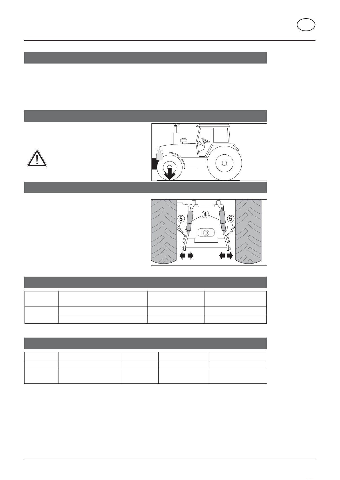
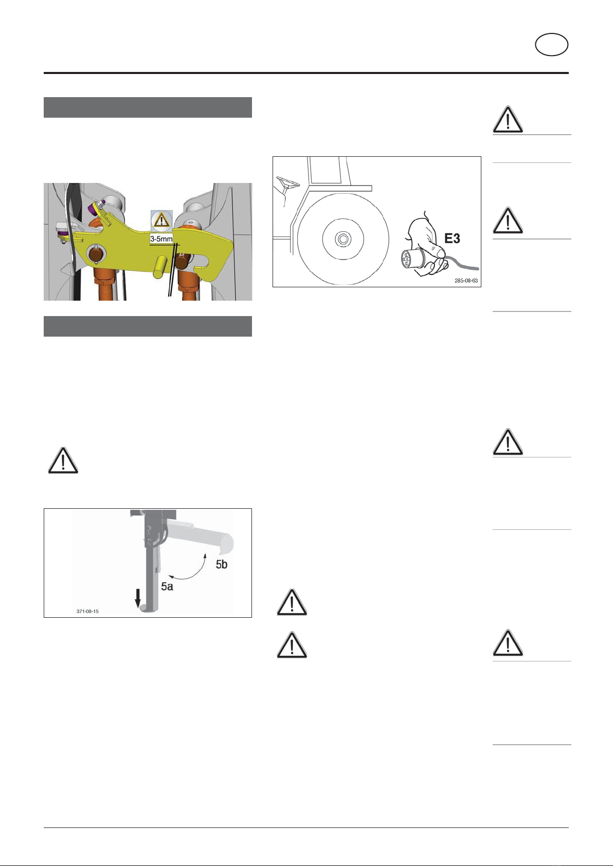
Set tyre tracking ...................................................... 27
Tyres ........................................................................ 27
Tine arms................................................................. 27
Rotor unit ................................................................. 28
Lubrication diagram ................................................. 30
Spring tines.............................................................. 32
Maintenance Setting the working width ................ 32
Lubrication chart ...................................................... 33
TOP 842 C/ TOP 962 C hydraulic plan................... 34
HYDRAULIC PLAN
TOP 842 C/ TOP 962 C hydraulic plan with single
rotor operation ......................................................... 35
TECHNICAL DATA
Technical data.......................................................... 36
Connections required .............................................. 37
Optional equipment:................................................. 37
Variations:................................................................ 37
Use of the swath rotor as intended .......................... 37
Type plate ................................................................ 37
Tyres ........................................................................ 38
SUPPLEMENT
Lubricants ................................................................ 48
Combination of tractor and mounted implement.......51

- 5 -
1600_GB-INHALT_2740
TABLE OF CONTENTS GB
CE sign
The CE sign, which is affixed by the manufacturer, indicates outwardly that this machine
conforms to the engineering guideline regulations and the other relevant EU guidelines.
EU Declaration of Conformity
By signing the EU Declaration of Conformity, the manufacturer declares that the machine
being brought into service complies with all relevant safety and health requirements.
Meaning of warning signs
Do not enter rotor area while driving motor is running.
Never reach into the crushing danger area as long as
parts may move.
Stay clear of swinging area of implements
495.173

- 6 -
0800_GB-AllgSicherheit_3842
GB
Travelling with implement in tow
The attached implement influences the travelling
characteristics of the towing vehicle.
• Danger of tipping exists when working on slopes.
• The driving must be adapted to the corresponding
terrain and ground conditions.
• The towing vehicle is to
be sufficiently equiped
with weights at thefront
or at the rear in order to
guarantee the steering
and braking capacity (a
minimum of 20% of the
vehicle's tare weight on
the front axle).
• Transporting people on the implement is not
permitted.
Coupling and uncoupling the implement
• Danger of injury exists when coupling the implement
to the tractor!
• When coupling, do not stand between tractor and
implement while tractor is reversing !
• No-one must enter the area between tractor and
implement unless both vehicles have been secured
against rolling with wheel chocks !
• Drive shaft connection or disconnection is only to
be undertaken when the motor has stopped.
Regulations for Use
Regulations for Use: See chapter „Technical Data“.
• The trailer‘s load limits (permitted axle load, support
load, total weight)may notbe exceeded.Therelevant
details are located on the right side of the trailer.
• In addition, observe the power limits of the tractor
being used.
Travelling on roads
• Observe the road rules
GENERAL SAFETY TIPS
20%
Kg
Important!
General safety
hints for the use
of this implement!
Before starting work
a. Before commencing work, the operator must be aware
of all operating devices and functions.The learning
of these is too late after having already commenced
operation!
b. Before commencing any work check that implement
is safe for road travel and operation.
c. The danger of being crushed or cut exists in the Pick-
up, cutting unit, tailgate and upper extension areas.
d. Before driving the vehicle, the driver must ensure that
nobody will be endangered and that no obstructions
are present. If the tractor driver does not have a clear
view of the roadway immediatelybehind the implement,
he must be guided when reversing.
e. Observe the safety information fixed to implement.
An explanation of what the individual graphic warning
symbols mean can be found on page 5.
f. Observe also the tips in the respective chapters and
in the supplement to this operating manual.
Checking before operation
The following tips should make preparing the implement
for operation easier. Detailled information for individual
points can be found in the respective chapters in this
operating manual.
1. Check that all safety equipment (covers, casings, etc.)
is in good condition and fixed in the proper positions
of protection on the implement
2. Grease and oil the implement according to the
lubrication chart. Check the gearing for tightness and
the oil level.
3. Check that tyres have the correct air pressure.
4. Check that wheel nuts are sitting firmly.
5. Ensure the correct p.t.o.-r.p.m.
6. Make the electrical connections to the tractor and
check that they are correct. Take note of the tips in
the operating manual!
7. Carry out the following adaptions:
• Drawbar height
• Cardan shaft length
8. Secure the implement only with the equipment
provided.
9. Cut drive shaft to correct length and checkthat overload
safeguard is functioning (see Supplement)
10.
Check the electronic unit function.
11.
Connect hydraulic lines to tractor.
• Check hydraulic hoses for damage and wear.
• Ensure the correct connection.
12.
All swivelling parts must be secured against dangerous
position changes.
13.
Check parking brake and service brake functions.

- 7 -
1600-GB_OVERVIEW_2740
GB
SPECIFICATION
Designations:
1. Inner feeler wheel
2 Transport locking device
3. Right rotor unit
4. Working width limiters
5. Tine bearing rack
6. Chassis
Overview
13
12
14
7. Left rotor unit
8 Outer feeler wheel (optional equipment)
9. Swath curtain
10.Tine cover
11. Lower link mounting and support stand
12.Spare wheel suspension bracket
13.Hose holder
14.Markings for maximum steering lock
3
2
1
9
11
10
8
8
7
6
1
4 5

- 8 -
1600-GB_SCHLEPPERVORAUSSETZUNG_2740
TRACTOR REQUIREMENTS
GB
Tractor
To operate the implements the following tractor requirements must be met:
- Tractor power: TOP 842 C from 55 kW / 75 HP
TOP 962 C from 63 kW / 85 HP
- Hitching: Lower link Cat. II
- Connections: See table "Necessary hydraulics and power connections"
Ballast weights
Ballast weights
The front of the tractor is to have sufficient ballast to
guarantee braking and steering capabilities.
At least 20% of the tractor’s tare weight
on the front axle!
Lifting gear (three-point linkage)
- The tractor’s lifting unit (three-point linkage) must be
designed for the load that occurs. (See technical data)
- The lifting struts are to be set at the same length (4)
using the relevant adjusting equipment
(See the tractor manufacturer’s operating manual)
- Select the rear position if the lifting rods can be adjusted
in various positions on the lower link. This relieves the
pressure on the tractor’s hydraulic system.
- The limiting chain or lower link stabilisers (5) are to
be set so that the coupled implement CANNOT move
sideways. (Safety measure for transportation)
Necessary hydraulic connections
Design Consumer Single-acting
hydraulic connection
Double-acting
hydraulic connection
Standard Lifting and lowering the rotor units X*)
Hydraulic working width adjustment X
*) Floating position required
Power connections required
Design Consumer Pin Volt Power connection
Standard Lighting 7-pin 12 V DC According to DIN-ISO 1724
Variant electrohydraulic single rotor
operation
2-pin 12 V DC according to DIN-9680
20%
Kg
371-08-16
371-08-16

- 9 -
1600-GB_Attaching_2740
ATTACHING THE MACHINE
GB
Safety
hints:
see Supplement A1
point 8a. - h.)
Before initially attaching the machine
1. Check the transportation locks:
Ifthe distance betweenthelockinghooks and lifting cylinder
bearing bolts is unevenly set, then the locking function will
be affected. Therefore, the distance must be checked by
the dealer after receiving the machine.
Attaching the machine
1. Couple the headstock on the tractor:
- Switch pto off before attaching
- Attach headstock to the lower link of the tractor
- Secure coupling pins correctly
- Position chassis frame correctly
2. Fold up support stand
Check that the headstock and the tractor
are connected correctly before folding
the support leg.
- Push support stand down with your foot and fold up
- The bolt engages automatically
Beware!
Once released, the
support stand
swivels up auto-
matically
- Crushing hazard
Beware!
Set the lower link
chains and/or
stabilisers so
that the attached
machine cannot
move sideways.
Beware!
Turn the motor off
before mainte-
nance and repair
works, remove the
ignition key and
secure the tractor
against rolling!
3. Make electrical connections
Lighting:
- Attach 7-pin plug to tractor (E3)
- Check that the lighting functions on the machine
Single rotor operation (variant):
- Couple the 2-pin plug on the tractor
4. Connect hydraulics
- Place lever on tractor control unit at floating position
(0)
- Ensure clean plug connections
- Connect hydraulic hoses
- Installthecord (Standard) orthecable and thecontrol
unit (single-rotor variant) in the tractor cabin
5. Fit cardan shaft
- Switch engine off and remove ignition key.
- Before fitting the cardan shaft, clean and grease the
machine's connection profiles and the pto.
- To start, install the wide-angle joint to the
machine.
- Then attach the cardan shaft to the tractor's pto.
- Secure the guard tubes for all cardan shafts against
rotating by attaching the safety chains.
Be advised!
Check the cardan shaft length prior to
initial operation and adjust if necessary
The cardan shaft must be specifically
adapted to each tractor !

- 10 -
1600-GB_Attaching_2740
ATTACHING THE MACHINE
GB
Trimming process
- To adjust the length, hold cardan shaft halfs in the
shortest operating position (L2) next to one another
and mark.
Shortest possible operating position (L2):
1. Lower hoist completely
2. Steering turned to lock.
(see adjacent illustration)
354-15-41
L2
For details see Chapter "Adapting the cardan shaft" in
supplement B of these Operating Instructions.
Parking the machine
The machine can be parked in working position as well as
in transport position.
Beware!
- Park the machine stably!
- Secure the machine against rolling with
wheel chocks.
Before leaving the machine, bring the
control unit to the floating position so
that the hydraulic lines can easily be
uncoupled later.
1. Fold in the support stand
- Unlock spring-loaded bolts (B)
- Swivel support stand (5a) up and let it engage
Be advised!
Only park the ma-
chine on flat, firm
ground!
Be ad-
vised!
Turn the tractor
engine off and
remove the key
before parking the
machine.
2. Uncouple lines and the drivetrain
- Pull the cardan shaft off and place it on the support
(6).
- Uncouple the hydraulic lines and place them in the
hose support (7) (If problems occur, bring the control
unit to floating position)
7
6
- Remove the cord (Standard) or the cable and the
control unit (single rotor raising) from the tractor
cabin
- Uncouple electric cable from tractor and place it on
the cable holder (7) (For single rotor operation, two
electric cables need to be uncoupled.)
- Uncouple implement from tractor.

GB
1600_GB-Operation_2740 - 11 -
OPERATION
General guidelines on working with the
machine
The p.t.o must be switched off before performing any work
in the rotor area.
Be advised!
Do not enter the working area or the area
around the rotors while the drive motor
is still running.
- Select the driving speed that picks up all the harvested
crop cleanly.
495.173
From transport position to working
position
075-09-05
Take note:
Loweringtherotorsshould becompleted
inone movementespeciallyin hilly areas.
Otherwise, stuttered raising/lowering of
individual rotors can occur in the short-
term. Increased danger of tipping!
After control unit 1 has been brought
to the neutral position, there could be
compensating movements by the rotor
arms.
Lowering the rotor
1. Release the locking bolt while simultaneously:
a. Setting the control unit 1 (rotor arms) to "Raise"
b. Pulling on the rope (or pushing the comfort-control
button)
Be advised!
Danger from ro-
tating tines. Turn
the swath rake off
before leaving the
cabin.
Ensure that nobody
is near the rake
during operation.
Note that danger
may also exist
from ejected cut-
tings and stones.
Stop work immedi-
ately as soon as
anybody enters
the danger zone.
Be advised!
Ensure that nobody
is in the dan-
ger area before
starting the swath
rake.
Be advised!
Changing from
working to trans-
port position is
only to be carried
out on flat, solid
ground.
Ensure that the
swivel area is
clear and that
nobody is stand-
ing in the danger
area.
2. Unlock the transport safety flap by setting control unit
2 (double-acting) to "Raise".
Do not raise further than the free-travel
drive position (F) or else the flap will fall
back down. If the flap falls down, move
control unit 2 down again and push the
transport safety flap back up.
STOP
F
Note:
Therotorarmswillstoploweringiftherope
is pulled or the comfort-control button
is pushed while the rotor arms are being
swivelled from the transport position to
the headland position.
3. Swivel rotor arms in working position by moving control
unit 1 (single-acting) to floating position.
Note:
The lowering speed of both rotor arms
can be set using the throttle (1) on the
relative lifting cylinder.
1
Ensure the lowering speed for both rotor
arms is equally set .

GB
OPERATION
1600_GB-Operation_2740 - 12 -
4. When tine arms have been removed:
Note:
When the TOP 962 C is in the transport
position, the tine arms must always be
removed in order to conform with the
statutory transport height.
With the TOP 842 C, the tine arms must
be removed to attain a transport height
of 3.6 m.
a. Refit the removed tine arms
Note the rotation direction of the
tines and the spring linchpin when
refittingthetines.The spring linchpin
must close in the rotation direction.
Note:
Fit the tine arms only when the
tractor drive is turned off.
b. Extending the rotor arms (TOP 962 C only)
To be able to fold the hoop guard to the next stage,
extend the tine arm until the pointer (2) reaches the
folding area (3).
2
3
c. Folding the hoop guard down
Onlygrip the hoopguard inthe area
designated to this purpose, right at
the very end, otherwise the danger
of crushing exists.
XXXXXXXXXX
From headland position to working
position
1. Swivel the rotor arms in working position by moving
control unit 1 (single-acting) to floating position.
- The cardan shaft drive does not have to be switched
off.
Note:
Switch the tractor's control valve to the
floating position in the working position
so that a clean ground adaptation of the
rotor units results.
From working position to headland
position
075-09-10
1. Swivelthe rotorarms to the headlandposition bymoving
control unit 1 (single-acting) to "Raise".
Operate control unit 1 until the height does not change
any more. (If the headland height is not appropriate see
"Setting headland height")
Settings on rotor chassis
Requirement:
- Level and solid ground
- 1.5 bar pressure in all tyres
- Themachine isattached to thetractorand in theworking
position
1. Set lateral incline
The rotor chassis should be slightly inclined to
theswath side toensure clean rakework.The side
rake start should be approx. 1.0 - 1.5 cm higher.
1. Lowering the rotor unit using the crank (1) -
until the inner tines just touch the ground.
1
Be advised!
Secure crank
handle in holding
bracket after set-
ting is completed.
Be advised!
Operating the im-
plement without
inner feeler wheel
is not permitted!
Operation without
feeler wheels is
not permitted!
Note
The height of the
chassis and
inner feeler wheel
does not have to
be re-adjusted
whenever the rake
height is altered.
Note
Ensure that the
swath rake drive
frame is in hori-
zontal position.

GB
OPERATION
1600_GB-Operation_2740 - 13 -
2. Adjusting the outer tines - approx. 1.0 - 1.5 cm
above the ground.
With a TOP 842 C, all the wheels (a-c) can
be adjusted using an eccentric screw.
a1
b1
b2
ca2
Witha TOP962C, thedual feelerwheel (c)
has a spindle for an adjustment system
a1
b1 b2
c
a2
Evenly set the wheels which are located
on the side of the rotor unit (a1 and a2
and/or b1 and b2)
a. Eccentric screw system:
3
2
a1
b1
b2
c
a2
1. Loosen the nuts (3) slightly using open-end spanner
No. 36.
2. Set the required incline using the eccentric bolt (2)
and an open-end spanner No. 36.
3. Retighten the nuts (3). (Tightening torque 280 Nm)
b. Adjustment spindle system:
1
2
1. Loosen the nuts (1)
2. Set the spindle (2) at the required length
3. Tighten the nuts (1)
2. Adjusting rake height
1. Set rake height using the hand crank (1) - individually for
eachrotorunit. Turn crank (1) anti-clockwise to increase
the distance of the tines to the ground. Turn crank (1)
clockwise to decrease the distance of the tines to the
ground.
- Inside tines should lightly touch the ground (approx.
10-20 cm) depending on forage quantity.
2,0 cm
- Adapt working height to ground conditions.
- The fodder becomes dirty and/or the sward is
damaged if the setting is too low.
- Check the setting frequently during operation.

GB
OPERATION
1600_GB-Operation_2740 - 14 -
3. Aligning the indicators
Requirement:
The raking height is set equally for both rotors
Align the height indicator (4) on both rotor units.
a. Open hose clip (5) underneath the rotor unit
b. Align the height indicator arrow (4) with the one on
the other rotor unit.
c. Re-tighten hose clip (5).
4
5

GB
OPERATION
1600_GB-Operation_2740 - 15 -
639-13-12
3,5 cm
2,0 cm
2,5 cm
Starting raking
Rake end
Example - left rotor with tandem chassis:
Requirement:
- Flat and solid ground
- 1.5 bar pressure in all tyres
- The machine is attached to the tractor and in the working position
1. Step:
Lower the tines using crank. The lowest tines should no
longer sweep the ground when the rotor is turned.
2. Step:
Set the lateral incline using eccentric bolts in rake start
position so that the first tines activated (rake start) have a
ground clearance of approx. 1 - 1.5 cm.
Note: Set both eccentric bolts
simultaneously on the relevant side.
3. Step:
Setting the rake height using crank handle. The ground
clearance at "rake start" position should now be approx.
3.5 cm. The ground clearance at "rake end" position should
now be approx. 2.0 cm.
4. Step:
Set the inner feeler wheel so that the tines in front have a
ground clearance of 2.5 cm.
5. Step:
Set the outer feeler wheel (multi feeler wheel) so
that it is only slightly weighted.
6. Step:
Set the distance of the outer feeler wheel to the rotor.
The distance (A) of the front outer feeler wheel to the
tine rotor can be set in 8.5 cm steps. There are three
adjustment possibilities.
Positionthefeelerwheelasclosetotherotoraspossible.
Further away from the tines for lengthy fodder.
Note:
If the outer feeler wheel is set to its
maximumlength, dangerof collisionwith
the tractor exists when driving in curves,
in the working or headland positions.
A
2
3
3. Step
3. Step
5. Step
4. Step
Be advised!
Operating the im-
plement without
inner feeler wheel
is not permitted!

GB
OPERATION
1600_GB-Operation_2740 - 16 -
Cardan shaft speed
The maximum cardan shaft speed is: 540 rpm
The recommended cardan shaft speed is approx. 450 rpm
Note:
Reduce the PTO speed if the harvested
material is torn back from the swath by
thetinesand returned totherakedsurface
(careless work).
Swath apron (optional equipment)
Swath apron height
There are five setting possibilities for the swath apron
height (1, 2, 3, 4, 5). Whereby (1) is the lowest and (5) is
the highest.
3
24
15
Use position 5 for straw, large fodder quantities or road
transport.
Setting the swath apron height:
1. Bring the machine to working position (see chapter
"From transport position to working position")
2. Bring the swath apron to transport position (up till end
position) by setting control unit 1 (single-acting) to
"Raise" until the swath apron reaches transport position
3. Park the tractor
4. Close the ball cock on Line 1
5. Turn the bolt (1) until it can be pulled out (flattened ring
part is upwards)
6. Set the chosen swath apron height by inserting the bolt
in the chosen position (flattened part upwards) and
tightening it.
7. Reopen the ball cock
8. Start the tractor.
Swath apron position is horizontal:
Theswathapron can beshiftedback andforthhorizontally.
8
8
7
7
9
9
6
6
1. Loosen the screws (6,7) underneath the strap and
remove them.
2. Retighten both straps at the chosen holes (6, 7, 8,
9) on the swath apron frame
Note:
Pay attention to attach both straps, front
and back, in the same position. Only this
waywill thestraps remainparallel toeach
other. If not, the geometry changes and
a collision may occur between the swath
apron and the frame.
Note:
Only enter the danger area if there is no
other option. Beforehand, make sure that
- the tractor motor is turned off and the
ignition key is removed
- the ball cock of the single-acting
hydraulic system is closed.
- the rotor arms are in working position
and the rotors are at a standstill.
- the combination-machine is secured
against rolling.

GB
OPERATION
1600_GB-Operation_2740 - 17 -
Single rotor operation (variant)
To be able to work more efficiently at the field boundary, it
is possible to bring one rotor to the headland position and
continue working with the other rotor.
Raising a rotor
1. Select the chosen rotor by moving lever S1 on the
single-rotor control unit to the right or left position.
2. Raise the preselected rotor by setting control unit 1
(single-acting) of the tractor to "Raise".
Working with the other rotor
1. Set the tractor control unit to neutral to prevent the
2nd rotor from also being raised.
2. Preselect the lowered rotor by bringing lever S1 on
the single-rotor control unit to the relevant position.
3. Setthetractor control unit1 (single-acting)tofloating
position
Raising the other rotor
1. Preselect the loweredrotoronthesingle-rotorcontrol
unit (S1). Normally, this rotor is already selected
because it has been used for work.
2. Raise the preselected rotor by setting control unit 1
(single-acting) of the tractor to "Raise".
Note:
With the optionally available flow divider:
Always select the specific rotor arm to
be raised, otherwise with the lever S1 in
middle position, the 2nd rotor arm will
be raised very slowly.
Lowering the raised rotor
1. Select the raised rotor by bringing lever S1 on the
single-rotor control unit to the relevant position.
2. Lowerthepreselectedrotorbybringingtractorcontrol
unit 1 (single-acting) to floating position.
Note: Set the single-rotor control lever
(S1) to middle position so as to lower the
second rotor at the same time. Because
the tractor hydraulic system is already
in floating position, the second rotor will
also be lowered.
Note: If both rotors are to be brought to
the transport position at the same time,
then start raising to transport position
onlywhen bothrotor arms havethesame
position.(working or headland position).
Otherwise the lower rotor arm will not
reach transport position.
Control unit Single rotor control unit
Use the operating unit of the single-rotor control unit to
preselect the rotor. The rotor to be controlled by control
unit 1 can be set with lever S1.
Left - left rotor
Centre - both rotors
Right - right rotor
S2
S1
S1... Rotor preselection
S2... Transport guard
Hydraulic working width adjustment
TOP 842C
Working width is infinitely adjustable
21 3
TOP 962C
2
13
The working width is changed via the dual-acting hydraulic
connection.
Set the working width only in headland position.
Any position can be chosen between the minimum working
width (1) and the maximum working width (3). Position (2)
is the free-travel position and it is important when opening
the transport locks.
Note: When adjusting the working width,
pay attention to the sliding limiter.
Note: The minimum working width (1) may
not be exceeded in the working position
and headland position.
To beable to fold theprotectionbars before
settingthereducedtransportheight,set the
working width on maximum (4). Otherwise
theprotectionbar maycollide with therotor
arm when it is folded. Caution: crushing
hazard!
Be advised!
Changing from
working to trans-
port position is
only to be carried
out on flat, firm
ground.
Ensure that the
swivel area is
clear and that
nobody is stand-
ing in the danger
area.
Be ad-
vised!
Switch the cardan
shaft drive on
only when there
is nobody in
the danger area
and once all the
protective devices
have been at-
tached.
Note:
For a rake with flow
divider, always
select the rotor
to be raised via
the single rotor
control unit.

GB
OPERATION
1600_GB-Operation_2740 - 18 -
Setting the curved track
The curved track can be adjusted if grass is left behind
outside the swath.
1. Parkthemachine on anevensurfaceand secure against
rolling. (use wheel chocks)
2. Take the three plastic covers (1) from the openings on
the underside of the rotor unit, to gain access to the
screws (2) on the curved track system.
1
3. Loosen the three screws (2) on the curved track.
4. Adjust the curved track: By rotating the rotor unit using
the tine bearers, adjust the curved track in the slot so
that fodder can be better collected.
2
5. Tighten the three screws (2).
6. Insert the plastic covers (1) in the openings.
7. Carry out a test run. Repeat the procedure until the
results are satisfactory.
Setting the headland height (both sides)
Rotate the sliding limiter under the rotor arms left and right
to adjust the headland height to the existing conditions.
up away from frame (+) higher headland
down away from frame (-) lower headland
Setting:
1. Loosen 2x support screw (4)
2. Rotate the sliding limiter
3. Tighten 2x support screw (4)
4
5
Thefactorysettingsinclude the support screw(4)positioned
centrallyin theslot so that the noses(5) belowon the sliding
limiter overlap each other.
Set the same headland height for both
rotor arms.

GB
1600_GB-TRANSPORT_2740 - 19 -
TRANSPORT
From working to transport position
075-09-07
Note:
When the TOP 962 C is in the transport
position, the tine arms must always be
removed in order to conform with the
statutory transport height.
The tine arms can be removed from the
TOP 842 C to achieve a transport height
of 3.60 m.
Carry out transport height reduction
before raising the rotor. (see chapter
"Reducing the transport height")
Raising the rotors
1. Swivel the rotor arms from working position to headland
by setting control unit 1 (single-action) to "Raise".
2. Move the swath width adjuster (position 2) by operating
control unit 2 (double-acting).
321
3. Swivel the rotor arms from headland to highest position
by simultaneously:
a. Skipping the headland safety device by pulling the
cord or pressing the comfort-control button (variant
single-rotor control).
b. Settingcontrolunit 1(single-acting) to"Raise".Move
the device using the control unit to cylinder limit stop.
4. Lower the rotor to transport height by setting control unit
2 (double-acting) to "Lower" until the cylinder reaches
limit stop.
Ignore the display "min." on the sliding
limiter (1). The sliding limiter indicator
is only relevant in the working position
It refers to the working width.
Be advised!
Changing from
working to trans-
port position is
only to be carried
out on flat, firm
ground.
Ensure that the
swivel area is
clear and that
nobody is stand-
ing in the danger
area.
Be advised!
For safety reasons
turn p.t.o. off and
wait for rotors to
come to a stand-
still.
Beware!
Before transport,
check that the
transport safe-
guard is correctly
locked! The trans-
port safeguard
locking hooks
must hook com-
pletely into jib.
Be advised!
Check the position
of the raising
cylinder prior to
transport. The
cylinder must be
in the narrowest
position!
5. Check that the transport safeguard is correctly locked.
(see figure). The bolt must be locked in place in the
locking hooks.
When parking the machine: Set control
units 1 and 2 to floating position to make
uncoupling the hydraulic hoses easier.
From headland to transport position
075-09-38
Raising the rotors
1. Move the swath width adjuster (position 2) by operating
control unit 2 (double-acting).
321
2. Swivel the rotor arms from headland to highest position
by simultaneously:
a. Skipping the headland safety device by pulling the
cord or pressing the comfort control button (variant
single-rotor control).
b. Settingcontrolunit 1(single-acting) to"Raise".Move
the device with the control unit to cylinder limit stop.
3. Lower the rotor to transport height by setting control
unit 2 (double-acting) to "Lower" until the cylinder has
reached the limit stop.
Ignore the display "min." on the sliding
limiter (1). The sliding limiter indicator
is only relevant in the working position
It refers to the working width.

GB
TRANSPORT
1600_GB-TRANSPORT_2740 - 20 -
4. Check that the transport safeguard is correctly locked.
(see figure). (see figure). The bolt must be locked into
place in the locking hooks.
When parking the implement: Set control
units 1 and 2 to floating position to make
uncoupling the hydraulic hoses easier.
Tine arm holder operation
1. Loosen the locking device by pulling the sliding bolt
handle (3) backwards in travel direction (a) and then
to the body (b).
3
a
b
2. Insert the tine arm, as shown in the illustration, or
take it out.
3. Push the sliding bolt (3) back - in the direction of
machine centre (b). The locking device engages in
the slot and the tine arms are secured.
Driving on public roads
Beware!
- Observe the official regulations of your
state/country.
- Driving on public roads may only be
undertaken as described in the chapter
"Transport position".
- Protection devices must be attached and
in proper working order.
-Beforetravellingbringallswivellingparts
into their correct positions and secure
against potentially dangerous position
changes.
- Check the lights are functioning before
setting off.
- Place guard strips on the spring tines
facing outwards.
This manual suits for next models
1
Table of contents
Other Poettinger Farm Equipment manuals

Poettinger
Poettinger NOVACAT 261 classic User manual

Poettinger
Poettinger NOVACAT 225 H User manual

Poettinger
Poettinger EUROTOP 851 A multitast User manual

Poettinger
Poettinger TOP 342 User manual

Poettinger
Poettinger EUROTOP 611 A TOPTECH PLUS User manual

Poettinger
Poettinger TOP 460 N User manual

Poettinger
Poettinger TOP 632 A User manual

Poettinger
Poettinger TOP 380 N User manual

Poettinger
Poettinger TOP 692 A User manual

Poettinger
Poettinger EUROTOP 421 A TOPTECH PLUS User manual