Poettinger TOP 342 User manual

Operator‘s manual
Translation of the original Operating Manual
Nr.
Rotary swather
99+2620.EN.80U.0
TOP 342
(Type SK 2610 : + . . 0839)
TOP 382
(Type SK 2620 : + . . 01489)
TOP 422
(Type SK 2630 : + . . 0977)
TOP 462
(Type SK 2640 : + . . 0265)

1900_GB-PAGE 2
Product liability, information obligation
Product liability obliges manufacturers and dealers to issue operating instructions for the machine at the point of sale and to instruct
the customer on the operation, safety and maintenance regulations governing the machine.
Confirmation is required to prove that the machine and the operating instructions have been properly handed over. For this purpose
you have received a confirmation e-mail from Pöttinger. If you have not received this mail, please contact your local dealer. Your
dealer can fill in the handover declaration online.
For the purposes of product liability law, every farmer is an entrepreneur.
In the terms of product liability law, damage to property is any damage arising due to the machine, but not to the machine, and an
excess (500 euros) exists for this liability.
Corporate damage to property within the terms of the product liability law is excluded from this liability.
Be advised! The operating instructions must also be handed over with any subsequent machine sale or transfer and the transferee
must be instructed in the regulations stated.
Pöttinger - Trust creates Afnity - since 1871
"Quality pays for itself." Therefore we apply the highest quality standards to our products which are constantly monitored by our
in-house quality management and our management board. Because the safety, perfect function, highest quality and absolute
reliability of our machines in operation are the core competencies for which we stand.
There may be deviations between these instructions and the product as we are constantly developing our products. Therefore no
claims may be derived from the data, illustrations and descriptions. Please contact your Specialist Service Centre for any binding
information about specific features of your machine.
We would ask you to please understand that changes to the scope of supply with regard to form, equipment and technical
specifications are possible at any time.
Any form of reprint, translation or reproduction, including excerpts, requires the written approval of Pöttinger Landtechnik GmbH.
All rights according to copyright laws remain expressly reserved by Pöttinger Landtechnik GmbH.
© Pöttinger Landtechnik GmbH – 31st October 2012
Refer to PÖTPRO for additional information about your machine:
Are you looking for suitable accessories for your machine? No problem! All the information you require is here at your disposal.
Scan the QR code on the machine's type plate or look under www.poettinger.at/poetpro
And if we don't have what your looking for, then your Specialist Service Centre is there for you with help and advice.

DE-1901 Dokum D Attachments - 3 -
PÖTTINGER Landtechnik GmbH
Industriegelände 1
4710 Grieskirchen, Austria
Tel. 07248 / 600 -0
Telefax 07248 / 600-2511
Please place a cross where appropriate. X
According to the product liability please check the above mentioned items.
INSTRUCTIONS FOR PRODUCT HANDOVER
Confirmation is required to prove that the machine and the operating instructions have been properly handed over. For this purpose you have
received a confirmation e-mail from Pöttinger. If you have not received this mail, please contact your local dealer. Your dealer can fill in the hand-
over declaration online.
Machine checked according to delivery note. All attached parts removed. All safety equipment, drive shaft and operating
devices at hand.
Operation, commissioning and maintenance of the machine or device discussed and explained to the customer on the basis
of the operating instructions.
Check tyres for correct air pressure.
Check wheel nuts for tight t.
Correct PTO shaft speed indicated.
Adaptation to the tractor carried out: Three point adjustment
Cardan shaft correctly cut to length.
Test run carried out and no defects detected.
Function explanation during test run.
Swivel in transport and working position explained.
Information about optional equipment is given.
Indication of unconditional reading of the operating instructions.
EN

- 4 -
1400_GB-INHALT_2620
EN
TABLE OF CONTENTS
Observe Sa-
fety Hints in
the supple-
ment!
CE sign
The CE sign, which is affixed
by the manufacturer, indicates
outwardly that this machine
conforms to the engineering
guideline regulations and the
other relevant EU guidelines.
EU Declaration of Conformity
By signing the EU Declaration of Conformity, the
manufacturer declares that the machine being brought
into service complies with all relevant safety and health
requirements.
Meaning of warning signs
Never reach into the crushing danger area as long as
parts may move.
Do not enter rotor area while driving motor is running.
495.173
Table of contents
TABLE OF CONTENTS
CE sign ...................................................................... 4
Meaning of warning signs.......................................... 4
OVERVIEW
Overview.................................................................... 5
WARNING SIGNS
Meaning of warning signs.......................................... 6
Position of the warning signs ..................................... 7
ATTACHING
Attaching of machines with 3-point hitch .................. 8
Swing headstock locking during road drive and for
parking....................................................................... 8
Parking the implement ............................................... 9
TRANSPORT AND WORKING POSITION
Switching to transport position................................. 10
Transport runs.......................................................... 10
Driving on public roads .............................................11
Change to working position ......................................11
OPERATION
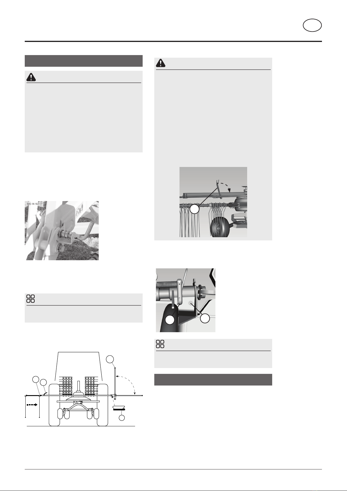
General guidelines on working with the machine .... 12
Working on slopes ................................................... 13
P.t.o. speed .............................................................. 13
Hydraulic lower link.................................................. 13
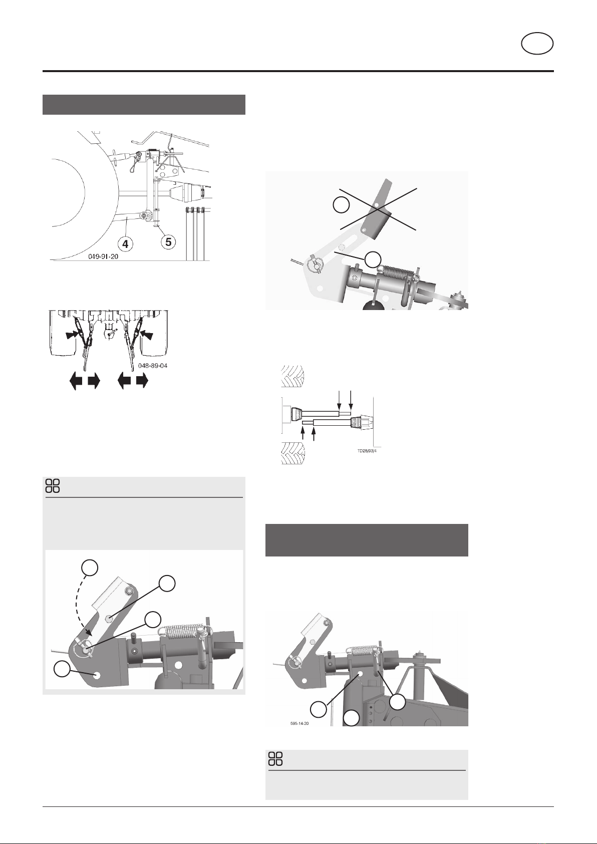
Setting the lifting support for the swath curtain.........14
Jockey wheel (5).......................................................14
Setting gyroscope inclination (without jockey
wheel) .......................................................................14
Setting gyroscope height ..........................................14
Tandem axle (optional fitting)....................................14
Hydraulic folding of the swath guard (optional
fitting)....................................................................... 15
Mechanical folding of safety brackets...................... 15
Setting the cam track............................................... 15
MAINTENANCE
Safety advice ............................................................17
Maintenance and Repairs.........................................17
Cardans ....................................................................17
Cleaning of machine parts........................................17
Winter storage...........................................................17
Lubrication chart ...................................................... 18
Tine arms................................................................. 19
Rotor unit ................................................................. 20
Spring tines.............................................................. 21
Lubrication chart ...................................................... 22
TECHNICAL DATA
Technical data.......................................................... 23
Appropriate use ....................................................... 23
Position of type plate................................................ 23
Special equipment: .................................................. 23
SUPPLEMENT
SAFETY ADVICE
Lubricants ................................................................ 30
Combination of tractor and mounted implement...... 33

- 5 -
1400-GB-ÜBERSICHT_2620
GB
OvErviEw
Overview
Designations:
(1) Crank for rotor height setting
(2) Three-point hitch with supporting leg
(3) Tine transport tray
(4) Rotor unit
(5) Swath apron
(6) Chassis
(7) Fork for locking the rotor during transport
(8) Safety bar
595-14-17
2
3
4
1
6
7
8
5

- 6 -
2000_EN-Warnbilder_2111
EN
Warning signs
Meaning of warning signs
1
(1x)
H
CZ
SK
Secure your right to product warranty by signing the delivery
declaration.
495,713
2
(1x)
540
540 rpm
495,310
3
(2x)
Do not enter the danger area of rotating rotors. Only enter the
danger area after the rotos have come to a stop.
495,173
4
(4x)
Never reach into the crushing danger area as long as parts
can move there.
495,171
5
(1x)
Read the operating instructions before putting the device
into operation.
494,529
6
(1x)
494.695
Nach den ersten Betriebsstunden
Muttern bzw. Schrauben nachziehen.
Resserer les vis écrous après les 10
premières heures de fonctionnement.
Tighten nuts and screws after the
first 10 hours of operation.
Na de eerste 10 werkuren bouton en
moeren natrekken.
Retighten all screws after the first hours of operation.
494,695

- 7 -
2000_EN-Warnbilder_2111
EN
Warning signs
Position of the warning signs
068-19-005
85 41264
4
8
38
3

- 8 -
2000_DE-ATTAWCHING_2620
EN
Attaching of machines with 3-point hitch
- Pin the implement to the 3-point attachment.
- Fasten the hydraulic lower link (4), so as the implement
cannot swivel out to the side. Insert and secure the
support feet on both sides (5).
- Attaching the upper link depends on whether you use
a jockey wheel (optional).
Utilization without jockey wheel:
- Insert the upper linkage in slot (A) or in the locked
slotted hole (L).
- Lock the slotted hole with the console (K).
TIP
First attachment without feeler wheel:
If the hatch (K) isn't screwed together with the slot, fix the
hatch (K) in the slot using screw (S) and the associated
pipe.
L
A
K
S
ATTACHiNG
Utilization with jockey wheel:
- Insert the upper linkage in the middle of the slotted
hole (L), so that the jockey wheel has enough
movement range in both directions.
- The console (K) must be dismounted so as not to
affect the movement range through the slotted hole.
L
K
- Before first utilization, check the cardan shaft length
andadjust if necessary(see also chapter "Cardan Shaft
Adjustment" in Annex B).
- When using the hydraulic swath cloth folding (optional),
connect the single action hydraulic hose.
Swing headstock locking during road
drive and for parking
For transport, you must lock the swing headstock (SB) with
the help of plug-in bolts.
C = working position
D = transport position
C
EN SB
TIP
Only reinsert locking pin with machine raised.

- 9 -
2000_DE-ATTAWCHING_2620
ATTACHING EN
Parking the implement
- Pin the bolt on the swing headstock (SB) in position D
Be advised!
Reposition bolts only with lifted machine
- Lower the implement with the tractor hydraulic system
and place it on the support foot
- Take out the PTO shaft and lay it on the shaft support
(E)
E
You mustnot use thesafetychain to suspend thecardan
shaft!
- Take out both support feet and insert them in lower
position
- Possibly disconnect the hydraulic hose
- Unhitch the implement from tractor

- 10 -
2000_EN-traNsport_2620
EN
WARNING
The rotor twisting independently and tine carriers on
the machine being perpendicular to the direction fo
travel may lead to risk of an injury resulting in death
or other serious injury.
• If possible, dismantle all of the tine carriers.
• Rotate the rotor into a position so that tine
carriers remaining on the rotor are pointing
in the direction of travel.
• Secure the rotor against rotation using the
anti-rotation lock (G). The anti-rotation lock
(G) is pivoted out in the next step “Swivel up
the safety bar”. Make sure that the anti-rota-
tion local is also engaged in a rotor arm.
G
7. Lift the machine
8. Insert the pins of the swivelling headstock (SB) in
position B.
BA
TIP
Only reinsert locking pin with machine raised.
Transport runs
Transport runs are defined as journeys from and to the
working location. If such runs include public streets and
lanes, then the machine must be in a roadworthy condition:
• Thelightfittingsshouldbefixedverticallytotheroad
and must function.
• Ifthelightingisdirtythenitmustbecleaned.
Switching to transport position
DANGER
Danger to life due to moving, rolling, tipping or
rotating parts.
Only carry out adjustments when the machine
• has been parked securely and steadfastly
on level, firm ground.
• the tractor engine is turned off and the pto
shaft is at a standstill.
• the tractor's ignition key has been removed.
1. Lower the machine if necessary
2. Insert the swath apron (9) completely and fasten it with
tommy screw (K).
3. Swiveluptheleftsafetybar,either manually orbymeans
oftheswiftcontrolunit(hydraulicswathapronswivelling)
Assure with a spring-loaded pin (splint horizontally).
4. Disassemble all tine carriers if possible and insert them
on the extension frame (Pos 1).
5. Rotate the rotor so that tine carriers remaining on the
rotor are pointing in the direction of travel.
TIP
Tine cariers not pointing in the direction of travel broaden
the machine unnecessarily.
6 Swivel up the safety bar on the right (10) and secure
it with a clip pin (6). Ensure that the anti-rotation lock
(G) has engaged in a tine arm.
TD 50/93/4
9
TrANSpOrT ANd wOrkiNG pOSiTiON

- 11 -
2000_EN-traNsport_2620
TransporT and working posiTion EN
Driving on public roads
• Observethestatutoryregulationsforyourcountry.
Supplement C contains information on attaching a
lighting system, valid for Germany.
• Driving on public roads may only be performed as
described in the Chapter "Transport position".
Hydraulic lower link
• Secure the hydraulic lower link (U) so that machine
cannot swing out sideways.
Change to working position
1. Switchthebolt on thepivotingheadstock(SB)inposition
A
BA
TIP
Only reinsert locking pin with machine raised.
2. Lower the device to the ground
3. Assemble all tine carriers on the gyroscope
4. Swivel the safety bars left (9) and right (10) and secure
them with spring-loaded pins, respectively clip pins (6).
(If the left safety bar is hydraulic, the left safety bar does
not need assuring.)
5. Pull swath apron out (X) and secure with tommy screw.
6. Adjust distance (X) according to needs.

- 12 -
2000_EN-EINSATZ_2620
EN
General guidelines on working with the
machine
DANGER
Life-threateningdangerexiststhroughrotatingrotors
and folding arms
• Turn the rake off before leaving the cabin.
• Switch off engine and remove ignition key
prior to any adjustment, maintenance or
repair work.
• Only carry out work in the rotor area when
the PTO shaft is stationary.
• Do not enter the rotor area while the drive
motor is running.
• Before switching on the drive motor, make
sure that the working area is free and that
no one is in the danger zone.
495.173
WARNING
Risk of serious injury due to thrown material and
stones
• Ensure that nobody is in the danger area
before starting the rake.
• Ensure that nobody is near the rake during
operation.
• Stop work as soon as anybody enters the
danger zone.
WARNING
Risk of a life-threatening or fatal injury if entering and
standing in the danger area during work.
• Ensure that there are no people or obsta-
cles in the pivoting area during work. The
machine swivels automatically to the centre
position (M) and is locked in this position.
• The lock is released automatically when the
machine is lowered again.
TIP
Select a driving speed that ensures the entire crop is
harvested cleanly.
TIP
Regularly check the rotor setting during use in order to
achieve a neat working result.
- In case of overload, turn into a lower gear.
- Switchthebolt on thepivotingheadstock(SB)inposition
A
BA
TIP
Only reinsert locking pin with machine raised.
- Lift the three-point trailer machine before narrow curves
and driving backwards.
OpErATiON

- 13 -
2000_EN-EINSATZ_2620
OPERATION EN
Setting the strut lengths:
Adjust the strut length so that there is approx. 1 mm clearance
between the heart and the centre bolt on each side when the
combination is fully impacted.
Working instructions:
1. Jack-knife the combination completely
2. Check the lateral play of the centre bolt on the inside of the
curve (1). Play should be about 1 mm.
1
3. Change the lengths of the damping struts:
a. Straighten the combination
b. Remove pins from rear end of cylinder rod
c. Extend cylinder rod
TIP
If the cylinder rod cannot be extended, reduce the
dampingvalue.(See“Adjustingthedamping value”)
Once the length has been changed, reset to the
original damping value.
d. Adjust the length of the cylinder rod using the adjusting
screw
e. Refit the cylinder rod
f. Jack-knife the combination - check the play - repeat
procedure until play is correctly set.
g. Repeat for the other damping struts
P.t.o. speed
- Max. p.t.o speed = 540 U / min.
The most suitable shaft speed is of about 450 U / min.
- If the feed is pulled by the tines from the swath back to the
stripe (unclean work), you must reduce the pto shaft speed.
Hydraulic lower link
- The lower links of the tractor must be locked laterally free of
play, to avoid the to and fro swivelling of the implement.
Working on slopes
WARNING
Riskof injuryresulting in death or otherseriousinjury
from tilting the tractor/trailer unit when driving round
bends on a slope.
• When the machine is raised by the lifting
gear when taking bends, the rotor swivels
automatically to the centre position. This can
lead to hazardous situations on slopes due
to the machine's inertia (tipping, slipping,
material breakage, etc.)
The damping struts (D) ensure that the
swivelling procedure is not jerky, but slow
and continuous.
EN
Damping bars (optional fitting)
For working on slopes, we recommend the use of
damping bars (D), as these increase driving safety.
Adjusting the damping value:
How hard or soft the damping struts react can be adjusted
here.
1. Change the damping setting with the countered screw
(1).
TIP
The damping behaviour of both damping struts should
be the same as far as possible.
1

- 14 -
2000_EN-EINSATZ_2620
OPERATION EN
Setting the lifting support for the swath
curtain
Set the spring compressor above the spindle (2), so that
the swath curtain can be folded up easily. A spring tension
that is too high can lead to injuries because the higher the
swath curtain gets, the more rapidly it folds up.
2
Jockey wheel (5)
When using the jockey wheel, for extremely uneven
surfaces, youneed a bettersettingofthetines to the ground.
To this end, the lower link must be pinned on even surface
in the middle of the slotted hole (see figure) so that it can
move freely up and down.
Setting gyroscope inclination (without
jockey wheel)
- For neat raking the gyroscope must be as horizontal
as possible. Only a very small inclination to the front is
allowed. You can set this inclination through the upper
link (7).
Setting gyroscope height
- The tines height is set through the crank handle (8),
tines should sweep the ground slightly. If the setting is
too low, the feed will be soiled, resp. the sward will be
damaged.
Tandem axle (optional fitting)
- The gyroscope should also be horizontal cross the
driving direction or inclined on the swath side max. 1.5 cm.
- Implements with tandem axle (10) must be lifted when
bending in narrow curves.
Transverse gradient setting:
1. Lower the rotor unit using the crank (1) - until the inner
tines just touch the ground.
2. Set the outer tines using eccentric bolt (2) - approx.
1.0 - 1.5 cm above ground.
a. Loosen nuts (3) slightly using a size 36 open-end
spanner.
b. Set the required inclination using the eccentric bolt
(2) and a size 36 open-end spanner.
c. Tighten the nut (3) again (tightening torque 280 Nm).

- 15 -
2000_EN-EINSATZ_2620
OPERATION EN
3
2
a1
b1 b2
a2
Hydraulic folding of the swath guard
(optional fitting)
1. Fold up the left deflector hoop hydraulically with the
single-action control unit
. Lock the deflector hoop in transport position by
means of the spring-loaded bolt. The splint snaps
in horizontal guide.
2. Set the single-action control unit in floating position
to fold down the deflector hoop.
Mechanical folding of safety brackets
1. Unlock the deflector hoop by means of the spring-
loaded bolt.
Boltonthe side oftheswath
curtain
Bolt right in the driving
direction
2. Fold the deflector hoop in the position of your choice.
3. Secure the deflector hoop in the position of your
choice by means of the spring-loaded bolt (1).
CAUTION
Risk of minor or moderate injury due to the guard
hoop jumping up.
• When folding pay attention on the side of
the swath apron that the spring support
does not speed up the guard hoop too
quickly.
Setting the cam track
The cam track can be adjusted if grass is left lying outside
the swath.
1. Park the machine on an even surface and secure it
against rolling off. (Use wheel chocks)
2. Take the three plastic plugs (1) from the openings on
the underside of the rotor unit to gain access to the
screws (2) on the curved track system.
1
3. Loosen the three screws (2) on the cam track.
4. Adjusting the cam track: Turn the rotor unit by the tine
arms and adjust the cam track in the slot, so that the
fodder is gathered more effectively.

- 16 -
2000_EN-EINSATZ_2620
OPERATION EN
2
5. Tighten the three screws (2).
6. Reinsert the plastic stoppers (1) in the openings.
7. Carry out a test run. Repeat the procedure until you are
satisfied with the result.

- 17 -
2000_EN_WARTUNG_2620
EN
Safety advice
WARNING
Themachinestartingtomoveor beingtippedmaylead
to risk of an injury resulting in death or other serious
injury during setting, maintenance or repair work.
• Park the machine only on solid, level
ground.
• Bring the device into working Position.
• Before carrying out setting, maintenance or
repair work to the machine, switch off the
tractor engine and remove the key from the
ignition.
• Do not work under the machine without it
being supported safely.
WARNING
Risk of serious injury through escaping oil.
• De-pressurize the hydraulic system prior to
any work on the system.
Maintenance and Repairs
To keep the machine in good condition also after long use,
please bear in mind the following instructions:
-Retighten all screws after the first hours of
operation.
- You must checkespeciallythezincscrews
and the swivelling frame connections.
- Always maintain the recommended air pressure in the
tires.
- Lubricate the lubricating parts according to the
instructions (see lubrication schedule).
Grease the lubrication nipples with universal lubricant
every 20 operation hours.
Cardans
- Lubricate cardan shafts every 8 operation hours.
- Take apart the sliding profiles and lubricate them well.
Cleaning of machine parts
Attention! Do not use a high pressure cleaner to clean
bearings and hydraulic parts.
- Danger of rusting!
- After cleaning, lubricate the machine according to the
lubrication chart and carry out a brief test run.
- Cleaningwith too much pressuremaydamage the paint.
Winter storage
- Clean implement thoroughly prior to winter storage.
- Park where protected from the weather.
- Protect exposed parts against rusting.
- Grease all lubrication points according to plan.
- Oilall ofthe articulations welland lubricatethebearings.
MAiNTENANCE

- 18 -
2000_EN_WARTUNG_2620
MAINTENANCE EN
Lubrication chart
20h
20h
595-14-091
21
1
(V)
TOP 342
0,80 [kg]
TOP 382
0,80 [kg]
TOP 422
1,00 [kg]
TOP 462
1,00 [kg]
8
h
FETT

- 19 -
2000_EN_WARTUNG_2620
MAINTENANCE EN
Tine arms
Change tine arms
- Loosen cover bolts (1).
1
- 1. Remove 2x bolts M12x110 (2)
2. Loosen 4x bolts M12x110 (3).
3
2
- Remove cover
- Pull tine arm out. Turn the rotor unit so that the old
tine arm can be removed from between the intake
and output control (see below).
- Install new tine arm. Turn the rotor unit so that the
new tine arm can be inserted between the intake
and output control (see below).
595-14-02
Direction of
travel
- Re-tightenbolts M12x110 with 1x nutand 2x Nordlock
washers (see illus.)
(tightening torque: 160 Nm)
Position the Nordlock washers with the rough milling
inside on top of one another. This means that both
washers have the fine milling outside.
- Attach cover to the new tine arm, fit it between the
coversandtightenthescrew. Tightenall the loosened
bolts (1) for the covers.
- Checkthetightness of theboltsand nuts afterapprox.
50 hours of operation and re-tighten if necessary.
-Payattentiontothe position of the dowelpinsin relation
to each other. see picture below - Detail B
B
Changing the bearing bush of the tine arms
TIP
Check the shaft (W) at least once a year at distance
(A) from the shaft.
• Thedistance(A)innormaloperationmustbeabout1
mm. If the shaft clearance (W) is greater, then it can
be corrected with shims.

- 20 -
2000_EN_WARTUNG_2620
MAINTENANCE EN
• Ifthedistance(A)isgreaterthan4mmthenthebushes
(B) on the inside of the tine arms are to changed.
Otherwise subsequent damage may occur to the
machine.
Rotor unit
Curved track
1. Interval: 50 h
2. Performance:
1. Install grease gun on grease nipple (1)
2. Turn the rotary unit to distribute the grease well
3. Install 3-4 strokes during one full turn
4. Perform 3-4 full turns
1
TOP 342
TOP 382
1
TOP 422
TOP 462
Gear of rotary unit: Refill grease
1. Interval: if needed
The gearbox of the rotary unit is greased for lifetime.
Nevertheless, check once a year whether the cogs still
are covered.
2. Implementation:
1. Open oil filling screw (1). The crown wheel toothing
is easily visible when the filling screw is open.
2. Refillfluidgreasein the fillingplug(1)until the toothing
of the crown wheel is covered completely.
3. If necessary, suck away any excess fluid grease.
4. Close the filling plug (1)
1
3. Fluid grease quantities
Indicative quantities after the complete emptying of the
rotary unit:
TOP 342 ~0.80 kg Mobilplex 44
TOP 382 ~0.80 kg Mobilplex 44
TOP 422 ~1.00 kg Mobilplex 44
TOP 462 ~1.00kg Mobilplex 44
In principle, the same procedure as for "Complete Liquid
grease": Fill by eye and aspirate the excess grease.
This manual suits for next models
3
Table of contents
Other Poettinger Farm Equipment manuals

Poettinger
Poettinger EUROTOP 851 A multitast User manual

Poettinger
Poettinger AEROSEM F 5000 User manual

Poettinger
Poettinger TOP 692 A User manual

Poettinger
Poettinger EUROTOP 421 A TOPTECH PLUS User manual

Poettinger
Poettinger EUROTOP 611 A TOPTECH PLUS User manual

Poettinger
Poettinger ALPINTOP 300 U User manual

Poettinger
Poettinger TOP 380 N User manual

Poettinger
Poettinger EUROTOP 1251 A User manual

Poettinger
Poettinger TOP 1403 C User manual

Poettinger
Poettinger TOP 460 N User manual