Poettinger EUROTOP 421 A TOPTECH PLUS User manual

Operator‘s manual
Translation of the original Operating Manual
Nr. 99+2611.EN.80U.0
Rotary Swather
EUROTOP 421 A TOPTECH PLUS
(Type SK 2611 : Chassis-Nr: +..00787 / MaschNr: +..01787)
EUROTOP 461 A TOPTECH PLUS
(Type SK 2991 : Chassis-Nr: +..00357 / MaschNr: +..01357)

1900_GB-PAGE 2
Product liability, information obligation
Product liability obliges manufacturers and dealers to issue operating instructions for the machine at the point of sale and to instruct
the customer on the operation, safety and maintenance regulations governing the machine.
Confirmation is required to prove that the machine and the operating instructions have been properly handed over. For this purpose
you have received a confirmation e-mail from Pöttinger. If you have not received this mail, please contact your local dealer. Your
dealer can fill in the handover declaration online.
For the purposes of product liability law, every farmer is an entrepreneur.
In the terms of product liability law, damage to property is any damage arising due to the machine, but not to the machine, and an
excess (500 euros) exists for this liability.
Corporate damage to property within the terms of the product liability law is excluded from this liability.
Be advised! The operating instructions must also be handed over with any subsequent machine sale or transfer and the transferee
must be instructed in the regulations stated.
Pöttinger - Trust creates Afnity - since 1871
"Quality pays for itself." Therefore we apply the highest quality standards to our products which are constantly monitored by our
in-house quality management and our management board. Because the safety, perfect function, highest quality and absolute
reliability of our machines in operation are the core competencies for which we stand.
There may be deviations between these instructions and the product as we are constantly developing our products. Therefore no
claims may be derived from the data, illustrations and descriptions. Please contact your Specialist Service Centre for any binding
information about specific features of your machine.
We would ask you to please understand that changes to the scope of supply with regard to form, equipment and technical
specifications are possible at any time.
Any form of reprint, translation or reproduction, including excerpts, requires the written approval of Pöttinger Landtechnik GmbH.
All rights according to copyright laws remain expressly reserved by Pöttinger Landtechnik GmbH.
© Pöttinger Landtechnik GmbH – 31st October 2012
Refer to PÖTPRO for additional information about your machine:
Are you looking for suitable accessories for your machine? No problem! All the information you require is here at your disposal.
Scan the QR code on the machine's type plate or look under www.poettinger.at/poetpro
And if we don't have what your looking for, then your Specialist Service Centre is there for you with help and advice.

DE-1901 Dokum D Attachments - 3 -
PÖTTINGER Landtechnik GmbH
Industriegelände 1
4710 Grieskirchen, Austria
Tel. 07248 / 600 -0
Telefax 07248 / 600-2511
Please place a cross where appropriate. X
According to the product liability please check the above mentioned items.
INSTRUCTIONS FOR PRODUCT HANDOVER
Confirmation is required to prove that the machine and the operating instructions have been properly handed over. For this purpose you have
received a confirmation e-mail from Pöttinger. If you have not received this mail, please contact your local dealer. Your dealer can fill in the hand-
over declaration online.
Machine checked according to delivery note. All attached parts removed. All safety equipment, drive shaft and operating
devices at hand.
Operation, commissioning and maintenance of the machine or device discussed and explained to the customer on the basis
of the operating instructions.
Check tyres for correct air pressure.
Check wheel nuts for tight t.
Correct PTO shaft speed indicated.
Adaptation to the tractor carried out: Three point adjustment
Cardan shaft correctly cut to length.
Test run carried out and no defects detected.
Function explanation during test run.
Swivel in transport and working position explained.
Information about optional equipment is given.
Indication of unconditional reading of the operating instructions.
EN

- 4 -
EN
1500_GB-Inhalt_2611
TABLE OF CONTENTS
Table of contents
TABLE OF CONTENTS
CE sign ...................................................................... 5
Meaning of warning signs.......................................... 5
ATTACHING TO TRACTOR
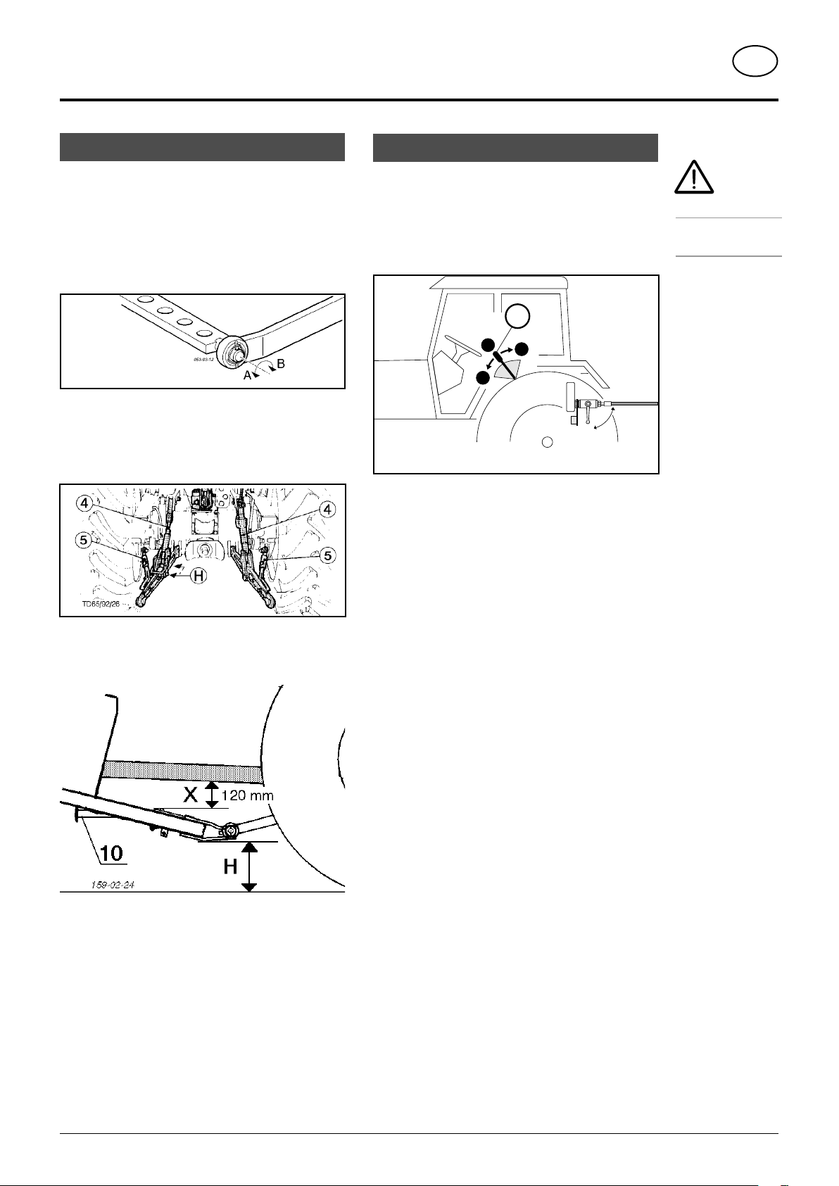
Initial attaching to tractor............................................ 6
Hydraulic connection ................................................. 6
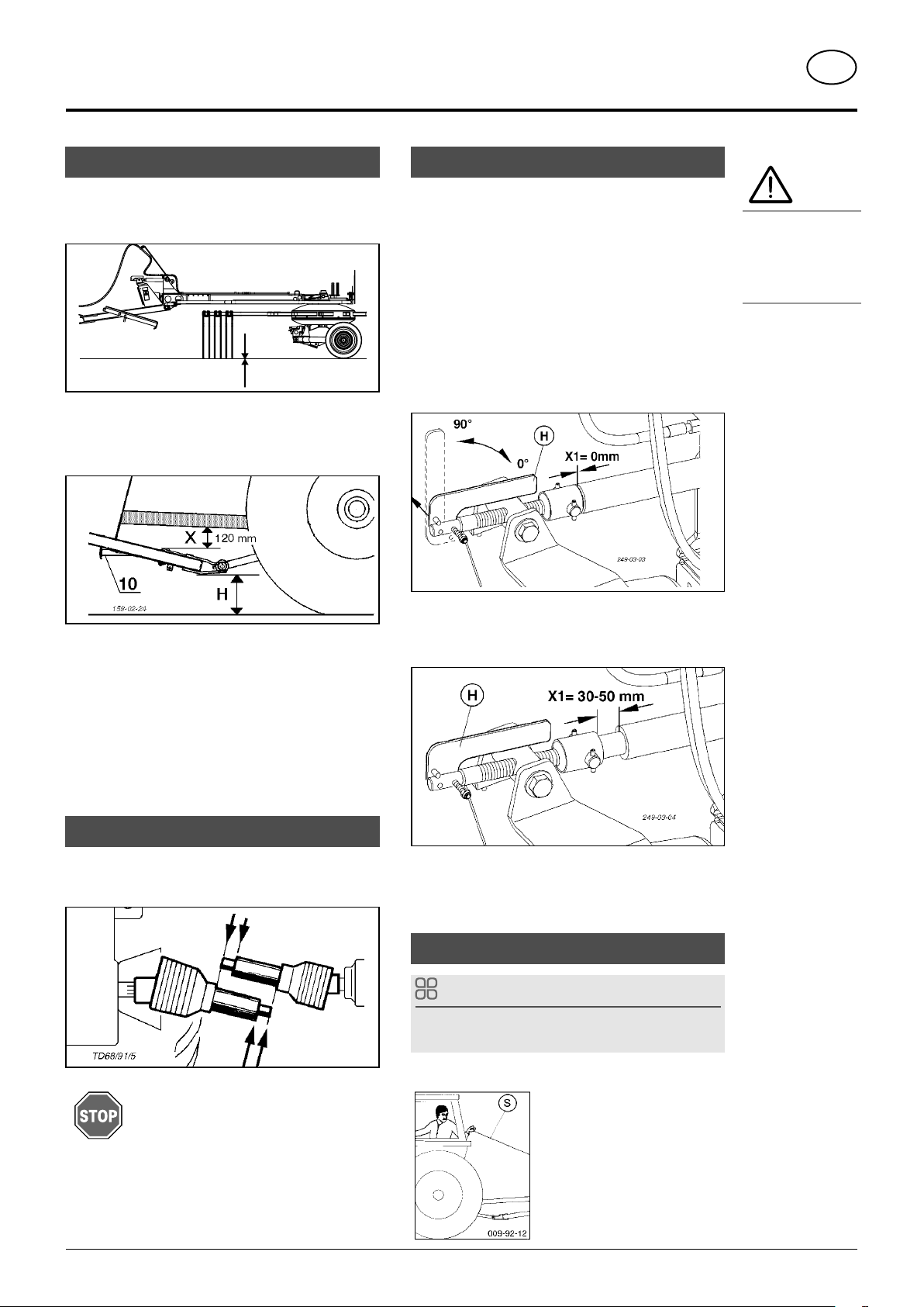
Preparations for initial use ......................................... 7
PTO shaft guarding.................................................... 7
Setting the threaded spindle ...................................... 7
Towing rope (option) .................................................. 7
LOWERING THE MACHINE
Lowering .................................................................... 8
TRANSPORT AND WORKING POSITION
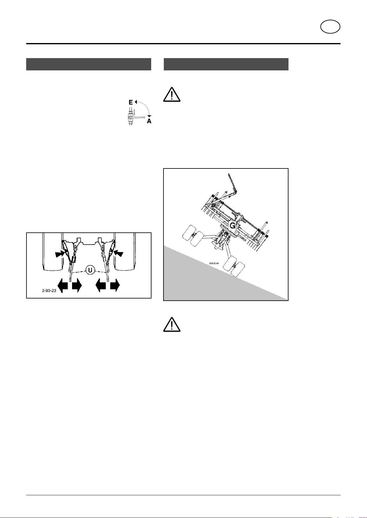
Driving on public roads .............................................. 9
Take care when turning on slopes! ............................ 9
Transport position .................................................... 10
Working position ...................................................... 10
OPERATION
Preparations for operation .......................................11
Important before starting work..................................11
p.t.o. speed...............................................................11
Hydraulic servo-valve (ST.........................................11
General guidelines for working with the
implement. ............................................................... 12
Setting the cam track............................................... 12
Hydraulic swath apron (optional) ............................. 13
Safety advice ............................................................14
General maintenance information.............................14
Cleaning of machine parts........................................14
MAINTENANCE
Parking in the open...................................................14
Winter storage...........................................................14
Cardans ....................................................................14
Hydraulic unit............................................................14
Lubrication points..................................................... 15
PTO shaft guarding ................................................. 15
Lubrication chart ...................................................... 15
Tine arms................................................................. 16
Rotor unit ..................................................................17
Spring tines...............................................................17
Lubrication chart ...................................................... 18
TECHNICAL DATA
Position of Vehicle Identification Plate ..................... 20
Defined use of the Rotary Swather.......................... 20
SUPPLEMENT
Lubricants ................................................................ 27

- 5 -
EN
1500_GB-Inhalt_2611
TABLE OF CONTENTS
CE sign
Recommendations
for work safety
All points refe-
ring to safety in
this manual are
indicated by this
sign.
Meaning of warning signs
TheCE sign, whichisaffixedbythemanufacturer, indicatesoutwardlythatthismachine conforms
to the engineering guideline regulations and the other relevant EU guidelines.
EU Declaration of Conformity.
By signing the EU Declaration of Conformity, the manufacturer declares that the machine being
brought into service complies with all relevant safety and health requirements.
Do not enter rotor area while driving motor is running.
Never reach into the crushing danger area as long as
parts may move.
Stay clear of swinging area of implements.
495.173

- 6 -
1300_GB-Attaching_2611
EN
ATTAChiNg TO TrACTOr
Hydraulic connection
The tractor must be fitted with at least one single-acting
hydraulic connection.
Connect hydraulic lines at tractor
- Connect hydraulic line to tractor only with closed stop
cock (position A).
A
E
TD 26/92/16
s
h
0
ST
Initial attaching to tractor
1. Attach the drawbar on tractor tool bar.
Important!
- The tool bar must be mobile (A-B)
- The holes in the tool bar must have a minimum
diameter of 30 mm.
- The left and right lifting struts (4) must be the same
length.
2. Secure the plug-in bolts with pins.
3. Fix the hydraulic lower link (5) so that the implement
cannot swivel out to the sides.
4. Swivel up the supporting leg (10) and secure it with
bolts.
5. Set the tractor hydraulic unit at the right height (H).
Pay attention to have a sufficient distance to the cardan
shaft (X), especially if you drive over ground tops!
6. Connect the tractor hydraulic lines.
- Stop cock closed (position A).
- Connect tractor hydraulic line.
7. Lower the implement
- Stop cock open (position E).
- Operate the single acting control valve (ST).
The implement lowers slowly to reach the ground.
Safety
hints:
see Annex A1 pt.
(8a. - 8i.)

- 7 -
1300_GB-Attaching_2611
EN
AttAching to trActor
Preparations for initial use
Important!
1. Working positions means that the implement is lowered
and the rotor tines slightly touch the ground (A1).
010-04-17
A1
2. The distance (X) between the PTO shaft and the tool bar
must have at least 120 mm in working position (standard
measure). Observe the distance "X" particularly when
driving over ground tops!
3. The position of the rotor tines (A1) should be somewhat
parallel to the ground; less inclination to the front is
permitted.
4.Set the correctdistance (X1) withthehelp of thethreaded
spindle.
For the machines with contact wheel (optional
equipment)" you need to set a pivoting range of the
drawbar for a good floor adjustment of the circular tines
(A1) on uneven surfaces.
PTO shaft guarding
- Before initial use, you must check and if necessary
adjustthe cardan shaft length (seealsochapter"Setting
of cardan shaft" in Annex B.
Important!
Always couple the wide-angle link to
tractor - not to machine!
Beware!
P.t.o. must be
switched off be-
fore carrying out
any work in the
rotor area.
Setting the threaded spindle
Set distance (X1)
1. Couple the machine to the tractor and bring it in working
position (see above).
2. Swivel the lever (H) upwards (90°).
3. Rotate the threaded spindle accordingly.
For machines without contact wheel:
Rotate the threaded spindle to the limit
X1 = 0 mm
For machines with contact wheel:
Rotate the threaded spindle to the reach the distance
X1 = 30 - 50mm.
4. Swivel down the lever (H) (0°).
- In this position (0°) the threaded spindle is secured
against twisting.
Towing rope (option)
TIP
The towing rope is needed only with the option “hydraulic
swath apron”.
- Lay the rope (S) into the tractor cab.

- 8 -
0700_GB-Abstellen_2611
GB
LOwEriNg ThE mAChiNE
Important!
Park machine
stabily!
Should problems occur when disconnecting:
- Move servo-valve (ST) briefly to "lower" position (s).
Doing this will reduce any possible pressure remaining
inthe connector and allowsatrouble-freedisconnection
of the hydraulic lines.
- Disconnect appliance from tractor.
Lowering
A
E
TD 26/92/16
s
h
0
ST
The machine can be lowered both from the working
position and from the transport position.
- Park machine stabily!
- Secureimplement fromrollingusingwheel
chocks!
Support Stand for EUROTOP 421 A
- Swing support stand down (5a) , secure with locking
pin (B)
Support Stand for EUROTOP 461 A
- Swing support stand down (5a)
- secure with locking pin (B)
- Pull off drive shaft and rest on support.
Do not rest drive shaft on safety chain!
- Close stopcock on every connector (pos. A) and then
disconnect hydraulic lines from tractor.
5a
B
5

- 9 -
0401_GB-Arbeits-Transportstellung_2611
GB
TrANSpOrT ANd wOrkiNg pOSiTiON
Driving on public roads
• Observe the official regulations of your country.
• Travelling on open roads may only be carried out as
described in chapter "Transport position".
• Close all hydraulic circuits (A).
• Protection devices must be in proper
condition.
• Before travelling bring all swivelling parts into their correct
positions and secure against dangerous changes to
position.
• Check that lighting functions before travelling.
• Important information can also be found in the
supplement of this operating manual.
Hydraulic lower link
- Fix the hydraulic lower link (U) in such a way that the
machine cannot swing out sideways.
Take care when turning on slopes!
Take care!
The tractor's travelling characteristics are
influenced by the weight (G) of the rotor
unit.This can leadtodangeroussituations,
especially on slopes.
Danger of tipping occurs
• when the rotor units are in a raised position
• when travelling in a curve with the rotor units raised
Safety advice
• Reduce speed in curves accordingly.
• It is better to travel in reverse on a slope
thantocarry outariskyturningmanoeuvre.

- 10 -
0401_GB-Arbeits-Transportstellung_2611
GB
Transpor
T
and working posi
Tand working posiT
T
ion
TionT
Safety hints:
see supplement-A1
(points 7., 8a. -
8h.)
• Changing from
working position
to transport
position is only to
be carried out on
even, firm ground.
Working position
1.
Stopcock opened (position E).
2.
Move single action servo-valve (ST) to "lower" position
and lower rotor units to the ground.
3.
Swing guard rails (6), left and right, outward
-
Release lock (A)
-
The locking pins catch automatically in the final
position.
Transport position
Changing to Transport position
1
.
Use single action control valve (ST)
2.
Lower machine to ground.
3.
Slide trap sheet (9) completely in and
secure with T-screw (K).
4.
Swing all guard rails (10) up
Thelocking pinscatchautomaticallyinthefinal position.
5.
Detach all tine arms and put on (position 1).
Attention!
If not all tine arms are taken off, the rotor
hastobesecured againstturningbymeans
of the fork (
G
).
The fork (G) is
mounted on the right
guard rail.
When raising the
guard rail the fork is
swung into the shaft
of the tine arm.
6.
Swing machine up into transport position (T1).
Use single action control valve (ST)
7.
Close stop valves (position A)
For safety, travel on roads only with stop valves closed!
010-04-16
1

- 11 -
2000_DE_Operation_2611
EN
OpErATiON
B e
advised!
Do not enter rotor
area while drive
motor is running.
Preparations for operation
1. Fit all tine carriers to both rotors.
- Fix tine carriers onto rotor arms and secure with
linch pin.
010-04-16
1
2. Swivel all deflector hoops (6) to the protection position
(left and right).
TD 44/94/11
6
6a
≈ 40 cm
3. Pull out the cloth and fasten with tommy screw.
- Normal setting is approx. 40 cm from the tines.
4. The tine height (A1) is adjusted by the spindle (8).
The tines should be slightly above the ground. Fodder
becomes dirty or turf becomes damaged if the setting
is too low.
010-04-17
A1
Important before starting work
1. Switch on p.t.o.
Only switch p.t.o. on when all protective fittings (covers,
protective cloths, claddings, etc.) are in good order and
are affixed to implement in the protection position.
2. Onlyswitchthe machineonin workingposition
and do not exceed the specified p.t.o. speed
(max. 540 rpm)!
A transfer, located near the transmission,
advises the p.t.o. speed that your machine is equipped
for.
p.t.o. speed
- Max. p.t.o. speed = 540 r.p.m.
The most suitable shaft speed is approx. 450 rpm.
- If tines are pulling fodder from swath back into raked
strip (messy work), then reduce the p.t.o. speed.
Hydraulic servo-valve (ST
- Move servo (ST) to "Neutral" or "Lower" position.

- 12 -
2000_DE_Operation_2611
EN
OperatiOn
Safety
advice
(see Supple-
ment-A1 pts. 1, 2,
3 and 4))
P.t.o. must be
switched off be-
fore carrying out
any work in the
rotor area.
General guidelines for working with the
implement.
Be advised!
Do not enter the rotor area while the
drive motor is running.
495.173
- Select a speed that ensures all harvested produce is
cleanly taken.
If overloaded, change back a gear.
To achieve clean work, rotor should be as horizontal as
possible. A very slight incline forward is allowed.
- The tines height is set through the crank handle (8),
tinesshould sweep the ground slightly. Fodderbecomes
dirty or turf becomes damaged if the setting is too low.
Set feeler wheel (optional)
- Tine height is set by appropriately positioning the linch
pin (V). Tines should lightly touch the ground. Fodder
becomes dirty or turf becomes damaged if the setting
is too low.
159-02-39
V
Setting the cam track
The cam track can be adjusted if grass is left lying outside
the swath.
1. Park the machine on an even surface and secure it
against rolling off. (Use wheel chocks)
2. Take the three plastic plugs (1) from the openings on
the underside of the rotor unit to gain access to the
screws (2) on the curved track system.
1
3. Loosen the three screws (2) on the cam track.
4. Adjusting the cam track: Turn the rotor unit by the tine
arms and adjust the cam track in the slot, so that the
fodder is gathered more effectively.
2
5. Tighten the three screws (2).
6. Reinsert the plastic stoppers (1) in the openings.
7. Carry out a test run. Repeat the procedure until you are
satisfied with the result

- 13 -
2000_DE_Operation_2611
EN
OperatiOn
Hydraulic swath apron (optional)
Operation
1. Automatic lowering of the hydraulic swath apron
· Pull the cord (to change the hydraulic valve)
2. Raising the hydraulic swath apron
· Pull the cord (to change the hydraulic valve and to
relieve the swath apron cycle)
· Operate control unit on tractor

- 14 -
EN
1400_GB-ALLG WARTUNG_BA
Hydraulic unit
Caution injury and infection hazard!
Liquids discharging at high pressure may penetrate the
skin. Therefore seek immediate medical help!
Make sure that the hydraulic system is suitable for the
tractor before connecting the hydraulic lines.
After thefirst 10hours inoperationand thereafter
every 50 hours in operation
- Checkhydraulicunitandpipingforleaksandifnecessary
re-tighten bolt connections.
Prior to every taking into operation
- Check hydraulic hoses for wear.
Replace any worn or damaged hydraulic hoses
immediately. The replacement hoses must meet the
manufacturer’s technical requirements.
Hose lines are subject to natural ageing. The period of use
should not exceed 5 – 6 years.
Parking in the open
Clean and protect the piston rods with
grease prior to longer periods parked
outside.
FETT
TD 49/93/2
Cleaning of machine parts
Be advised! Do not use high-pressure washers for the
cleaning of bearing- and hydraulic parts.
- Danger of rust!
- After cleaning, lubricate the implement according to
the lubrication plan and perform a brief test run.
- Cleaning pressure
being too high
may damage
the paint.
Safety advice
• Switch off engine prior to any adjustment, maintenance
or repair work.
Winter storage
- Clean implement thoroughly prior to winter storage.
- Put up protection against weather.
- Change or top up gear oil.
- Protect exposed parts from rust.
-Lubricateallgreasingpoints accordingtolubricationchart.
- Disconnect terminal, store dry and protected from frost.
Cardans
- See information in Attachment
Please observe the following for maintenance!
The instructions in these Operating Instructions apply.
If no particular instructions are available here, then the
informationinthe instructions suppliedbytherespective
cardan shaft manufacturer apply.
General maintenance information
Please observe the infiormation below to maintain the
implement in good condition even after a long period in
operation:
- Re-tighten all bolts after the first
hours in operation.
Thefollowingshouldbe checked
in particular:
Blade bolt connections at mower
Tine bolt connections at rake and
tedder
Spare parts
a. Original parts and accessories are specially designed
for the implements.
b. We expressly point out that we have not tested or
approvedanyoriginalparts andaccessories notsupplied
by us.
c. The installation and/or use of such products may under
certain circumstances negatively modify or impair the
propeties of the implement as specified in the design.
Any liability on the part of the manufacturer is excluded
inthe eventof anydamage due to the use of non-original
parts and accessories.
d. Anyunauthorisedmodificationsortheuseofcomponents
and attachments at the implement rules out any liability
on the part of the manufacturer.
General maintenance
Safety advice
• Switch off engine
and remove igni-
tion key prior to
any adjustment,
maintenance or
repair work.
• Only perform
work underneath
the implement
with secure sup-
ports.
• Re-tighten all
bolts after the
first hours in
operation.
• Only park imple-
ment on flat, firm
ground.
Repair information
Please observe the
repair information
in the Attachment
(If available).
Safety advice
Clean the cou-
pling plug of the
hydraulic hoses
and the oil socket
prior to each con-
nection.
Note any abrasion
and clamping
points.
mAiNTENANCE

- 15 -
1400_GB-WARTUNG_2611
GB
Maintenance
Lubrication points
Symbols have been affixed at
different points on the machine.
This indicate one or several
lubrication points.
• Remove cover (90)
• Grease lubrication points according to lubrication chart.
FETT
PTO shaft guarding
- Lubricate PTO shafts every 8 operating hours
- Take out the sliding profiles and lubricate well
FETT
1
1 1
20
h
1J
20
h
(100 )
h
1 1
1 1 1 1
1
(100 )
h
212-03-06
(V)
0,8 Liter 1J
Lubrication chart

- 16 -
1400_GB-WARTUNG_2611
GB
Maintenance
Tine arms
Change tine arms
- Loosen cover bolts (1).
1
- 1. Remove 2x bolts M12x110 (2)
2. Loosen 4x bolts M12x110 (3).
3
2
- Pull off cover
- Pull out tine arm. Turn the rotor unit so that you can
pull out the old tine arm between intake and outtake
(see below).
- Insert new tine arm. Turn the rotor unit so that the
new tine arm can be inserted between the intake
and output control (see below).
- Re-tightenboltsM12x110with1x nut and2x Nordlock
washers (see Fig.)
(tightening torque: 140 Nm)
Position the Nordlock washers with the rough milling
inside on top of one another. This means that both
washers have the fine milling outside.
Note:
Pay attention to the
position of the
dowel pins!
(see Detail B -
Fig.: 289-12-20)
- Securecoveron the newtinearm, insertbetweenthe
covers and tighten screw. Tighten all the loosened
bolts (1) for the covers.
- Checkthetightness of theboltsand nuts afterapprox.
50 hours of operation and retighten if necessary.
B

- 17 -
1400_GB-WARTUNG_2611
GB
Maintenance
Be advised!
The hydraulic
system must be
rendered pres-
sureless prior to
any work on the
system.
Changing the bearing bush of the tine arms
• The distance (A) in normal operation must be of about
1 mm. If the clearance of the shaft (W) is greater, then
it can be corrected with shims.
• If the distance (A) is greater than 4 mm then the bushes
(B) at the inside of the tine arms are to changed.
Otherwise subsequent damage to the implement may
occur.
Rotor unit
Cam track
Interval: 50 h
Implementation:
- Apply the grease gun to the grease nipple (1)
- Turn the rotor to ensure that the grease is evenly
distributed
- Apply 3-4 strokes during a full rotation
- Make 3-4 full rotations
1
TOP 421A
TOP 461A
Be advised!
Check distance (A)
of shaft (W) at
least 1x annually!
Spring tines
Check the attachment bolts (S) of the spring tines after
the first 10 hours in operation and re-tighten if necessary
(tightening torque: 100 Nm).
The outer tines are shorter and thicker.
If the implement has a tine loss securing device, the two
outer tines are connected; if you want to change one of
the two outer tines, you have to also remove the bolt of
the other tine.
Z
s

Lubrication chart
Xhafter every X hours operation
40 F all 40 loads
80 F all 80 loads
1 J once a year
100 ha every 100 hectares
BB if necessary
FETT
GREASE
Oil
= Number of grease nipples
(III), (IV) see supplement „Lubrificants“
[l] Litre
Variation
See manufacturer’s instructions
Rotations per minute
15 mm
10 mm
100-12-06
Always screw in measuring stick up to stop.

- 19 -
0800_GB-TechDaten_2611
GB
TEChNiCAL dATA
EUROTOP 421 A Type SK 2611
Number of rotors .....................................................................1
Number of tine arms per rotor ................................................ 12
Number of double tines per tine arm ........................................4
Working width (raking width)..............................................4,2 m
Transport width.................................................................. 2,1 m
Transport length................................................................. 4,1 m
Transport height.................................................................2,6 m
Parking height....................................................................2,2 m
Weight minimal, with drive shaft ..................................... 680 kg
Weight maximal, with drive shaft
and all optional extras.......................................................740 kg
Required power .............................................ab 30 kW (40 PS)
P.t.o. speed max. ..........................................................540 rpm
drive shaft overload safety............................................. 800 Nm
Tyres on the rotors.................................. 18x8,5-8 6 Ply rating
1,5 - 2 bar
Highest permitted speed ............................................... 30 km/h
Permanent sound emmission level ..............................81 dB(A)
Necessary connections
• 1 single-action hydraulic connection
pressure min.: 120 bar
pressure max.: 180 bar
• 7-pole electric connection for lighting (12 Volt)
All data is subject to change
4100 mm
(EUROTOP 421 A)
2100 mm
(EUROTOP 421 A)
4300 mm
(EUROTOP 461 A)
2430 mm
(EUROTOP 461 A)
EUROTOP 461 A Type SK 2991
Number of rotors .....................................................................1
Number of tine arms per rotor ................................................ 12
Number of double tines per tine arm ........................................4
Working width (raking width)..............................................4,6 m
Transport width..................................................................2,4 m
Transport length.................................................................4,3 m
Transport height.................................................................2,6 m
Parking height....................................................................2,2 m
Weight minimal, with drive shaft ..................................... 775 kg
Weight maximal, with drive shaft
and all optional extras...................................................... 835 kg
Required power .............................................ab 30 kW (40 PS)
P.t.o. speed max. ..........................................................540 rpm
drive shaft overload safety............................................. 800 Nm
Tyres on the rotors.................................. 18x8,5-8 6 Ply rating
1,5 - 2 bar
Highest permitted speed ............................................... 30 km/h
Permanent sound emmission level ..............................81 dB(A)
All data is subject to change

- 20 -
0800_GB-TechDaten_2611
GB
TECHNICAL DATA
Defined use of the Rotary Swather
The
“EUROTOP 421 A, EUROTOP 461 A”
Rotary Swather is intended solely for normal use in agricultural work.
•
The swathing of forage, silage fodder and straw.
Any other uses are regarded as not included in this definition.
The manufacturer takes no responsibility henceforth for any resulting damage which may occur. The user carries sole
risk.
•
The keeping of operating, service and maintenance requirements layed down by the manufacturer also come under
the heading of „defined use“.
Important!
Please enter the
number onto the
front page of the
operating manual
immediately after
taking delivery
of the vehicle/
implement.
Position of Vehicle Identification Plate
The chassis number is engraved on the name plate illustrated on the left. Warranty claims, enquiries and spare parts
orders cannot be made without quoting the chassis number.
Please enter the number on the title page of the Operating Instructions immediately on taking delivery of the vehicle/
equipment.
This manual suits for next models
1
Table of contents
Other Poettinger Farm Equipment manuals

Poettinger
Poettinger NOVACAT 225 H User manual

Poettinger
Poettinger NOVACAT 261 classic User manual

Poettinger
Poettinger EUROTOP 611 A TOPTECH PLUS User manual

Poettinger
Poettinger TOP 1403 C User manual

Poettinger
Poettinger TOP 662 User manual

Poettinger
Poettinger TOP 632 A User manual

Poettinger
Poettinger TOP 460 N User manual

Poettinger
Poettinger EUROTOP 1251 A User manual

Poettinger
Poettinger EUROTOP 851 A multitast User manual

Poettinger
Poettinger TOP 342 User manual