Poly-Tex FieldPro Gothic High Tunnel 20 User manual

1
Installation Instructions
PO Box 458 • 27725 Danville Ave. • Castle Rock, MN 55010 • poly-tex.com
U.S. & Canada Toll Free 800-852-3443 • (651) 463-7009 • fax (651) 463-2479 Rev AK-210121

2
Thank you for purchasing a FieldPro Gothic High Tunnel Greenhouse.
The FieldPro has been carefully engineered to provide years of faithful
service.
This installation manual covers the 20 and 24 FieldPro Series. The main
structural components are dierent for each FieldPro Series, however, both
units share most smaller ttings and hardware. As such, the assembly pro-
cedure of a 20 unit is very similar to a 24 unit.
Wherever an assembly procedure or specic part is dierent between a 20
unit and a 24 unit — the dierences are clearly explained.
Where this icon appears you will be alerted to
a useful installation tip or an optional way of
performing an installation operation.
Where this icon appears you will be alerted to
a Time-Saving tip that will help speed up the
FieldPro installation.
Safety Guidelines .......................................... 3
Limited Warranty ........................................... 4
Overview of FieldPro ....................................... 5
Gothic 20 Main Components Identication.................... 6
Gothic 24 Main Components Identication .....................7
Standard Fittings and Hardware.............................. 8
Building Site Layout ........................................ 9
Layout of Ground Support Locations ..........................10
Ground Stake installation Options ............................11
Ground Stake and Ground Stand Installation ...................12
Ground Stake Installation in Concrete Pier.....................13
Building Side Sub-Assembly ................................14
Building Main Frame Sections................................15
Erecting Main Frame Sections ...............................16
Adding Diagonal Braces ....................................17
Side Purlin Installation ......................................18
Adding Main Frames and Side Purlins.........................19
Peak Purlin Installation .................................20–21
Truss Frame Assembly ................................. 22–23
Installing Wood Side Rails ............................. 24–25
Plain End Wall Wiggle Wire Base Material Installation ..........26
Plain End Wall Poly Installation . . . . . . . . . . . . . . . . . . . . . . . . . . . . . . 27
Open Doorway – Part 1 and Part 2 ...................... 28–29
Wiggle Wire Installation ....................................30
Installation of Roof Poly – General Instructions .................31
Installing Roof Poly on FieldPro with Roll-Up Side Curtain....... 32
Installing Ground-to-Ground Roof Poly ....................... 33
Optional Door Kit w/ Metal Frame Installation ..............34–37
Optional Roll-Up Curtain Installation ......................38–41
Introduction
Index

3
WARNING
This structure is intended to be self-sup-
porting, provided it is constructed with all
frames, hardware, sheathing, sheeting,
bracing, cables, and membrane in place,
and secured to the foundation as shown in
the manual. Stability during construction,
from winds and loads imposed during erec-
tion, is the sole responsibility of the installer.
Observe safety codes required by the local
jurisdiction, and relevant safety practices for
working at heights. Avoid the risk of electri-
cal shock from overhead lines or electrical
storms. Poly-Tex recommends contracting
a licensed electrician to perform electrical
work. Eye protection is recommended under
all circumstances and hearing protection is
recommended when cutting components
with power tools.
DANGER
No part of this structure is engineered to
function as an anchorage point for a fall
arrest system. Use a safety net or work from
a safe work platform (i.e. scaolding).
Select a calm day for work. Wind can be
sucient enough to knock materials or
workers o a work platform or ladder,
resulting in a potentially deadly fall.
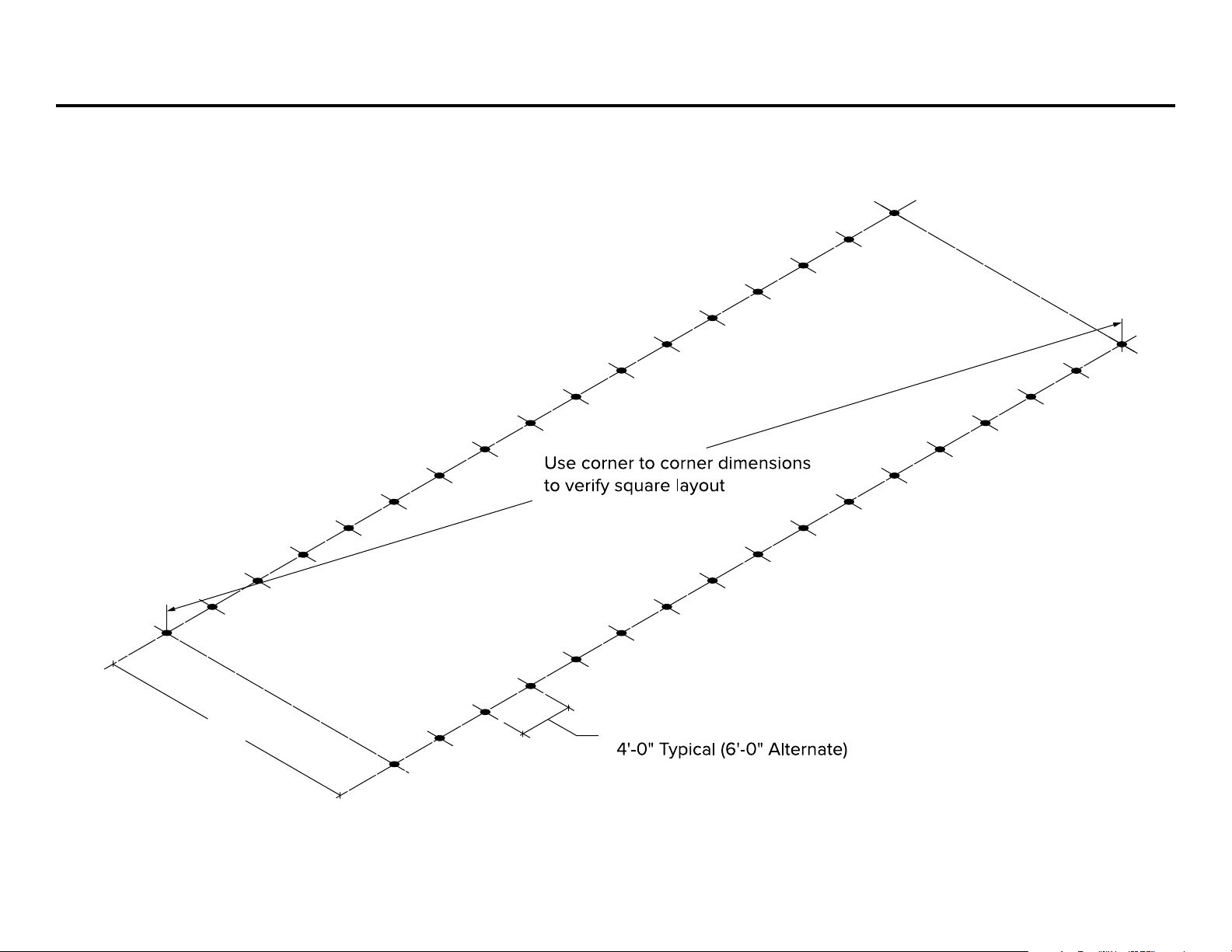
Overview of assembly procedure
While each structure and site is unique, and
may require special considerations, these
instructions are for a tilt-up method (where
frames are assembled on the ground and
tilted onto ground stakes or anchor rods
using ropes or lifts). If installer is not
condent to erect the structure, Poly-Tex
suggests hiring a general contractor,
carpenter, or similar licensed business
familiar with construction, to assemble
and erect the structure.
DANGER
Do not overload structure.
Consult with a Poly-Tex representative prior
to adding any amount of weight over the
specied capacity of this structure. Basket
purlins, shelving or any objects of signicant
weight shall not be hung, attached, or
secured to roof or truss members in a
manner that will overload the structure.
WARNING
Do not walk on polycarbonate sheets.
If structure is to be covered with polycar-
bonate sheets, always use scaolding for
the erection process to avoid damage to
sheeting and to ensure safety. Polycarbon-
ate sheeting has UV coating protected with
vinyl lm on the exterior surface. Install
sheets with the lm intact and toward the
exterior. Remove lm once the sheet has
been fastened in place.
Safety Guidelines
PLEASE READ THE INSTALLATION INSTRUCTIONS CAREFULLY BEFORE BEGINNING TO
ASSEMBLE THE STRUCTURE. SAVE THESE INSTRUCTIONS FOR FUTURE REFERENCE.
Poly-Tex does not warrant that this structure or foundation will comply with local or state
building codes. There is no guarantee of the load capacity of the structure for snow, wind,
seismic, or other loads unless buyer has received certified engineering drawings with the
structure, and Poly-Tex does not warrant that the frame or foundation will comply with
local or state building codes in buyer’s location.

4Poly-Tex, Inc. Limited Warranty
Poly-Tex, Inc. warrants its products to be free from defects in material and workmanship for a period of (1) year
from date of invoice. This warranty is provided to the original purchaser of the product and is not transferable.
Poly-Tex does not warrant parts not manufactured by Poly-Tex, but does assign any transferable manufacturer
or supplier warranties. Should any defect be found, full repair of replacement will be rendered to the custom-
er at no cost following inspection by a Poly-Tex representative and the return of the defective product to our
Castle Rock, MN factory. Expenses for removal or reinstallation of defective products will not be covered by
the warranty. The sale of custom projects are nal and are not eligible for refund.
POLY-TEX SHALL NOT BE HELD RESPONSIBLE FOR ANY SPECIAL OR CONSEQUENTIAL DAMAGES,
OR FOR ANY DELAY IN PERFORMANCE OF THIS WARRANTY BEYOND OUR CONTROL. THIS WARRANTY
IS EXCLUSIVE AND IN LIEU OF ALL OTHER WARRANTIES WHETHER IMPLIED, WRITTEN, OR ORAL
INCLUDING THE WARRANTIES OF MERCHANTABILITY AND FITNESS FOR A PARTICULAR PURPOSE.
ADDITIONALLY, THERE IS NO GUARANTEE OF THE LOAD CAPACITY OF THE STRUCTURE FOR SNOW,
WIND, SEISMIC, OR OTHER LOADS UNLESS BUYER HAS RECEIVED CERTIFIED ENGINEERING DRAWINGS
WITH THE STRUCTURE AND POLY-TEX, INC DOES NOT WARRANT THAT FRAME WILL COMPLY WITH
LOCAL OR STATE BUILDING CODES IN BUYERS LOCATION.
This warranty does not cover damage from customer abuse, misuse, improper installation, customer
modications, customer negligence in performing normal maintenance, damage resulting from acts of nature.
REV - 11/20

5Overview of FieldPro 20and 24
Straight Side
Diagonal Brace
Ground Stake/Stand
Steel Flat
Bracket
Wiggle Wire
Channel
“L” Bracket
All Lumber
(by others)
Middle Section
Truss Purlin
Purlin Cross
Connector
Peak Section
Peak Brace
Peak Brace
Corner
Bracket
2U-Clamp
1.66U-Clamp
Peak Purlin
U-Channel

6Gothic 20Main Components Identification
RR2109
9'-8" R.F. U-Channel w/Swage
GS2405
Ground Stand 2"x 36"
HP3541
HT Peak Section (Gothic 20')
HP3506 Diagonal Brace 78"
(6 ft. spacing)
GS2404
Ground Stake 36"
HP3505 Diagonal Brace 58"
(4 ft. spacing)
HP3542
HT Middle Section (Gothic 20')
HP3503
HT Peak Brace 111"
HP3340
9'-8" Truss Purlin w/Swage-Red
Customers will receive GS2404 or GS2405
depending on the type of installation.
See page 12 for installation options.
HP3540
HT Straight Side
(Gothic 20')

7Gothic 24Main Components Identification
RR2109
9'-8" R.F. U-Channel w/Swage
GS2405
Ground Stand 2"x 36"
HP3506 Diagonal Brace 78"
(6 ft. spacing)
GS2404
Ground Stake 36"
HP3505 Diagonal Brace 58"
(4 ft. spacing)
HP3545
HT Middle Section (Gothic 24')
HP3503
HT Peak Brace 111"
HP3340
9'-8" Truss Purlin w/Swage-Red
Customers will receive GS2404 or GS2405
depending on the type of installation.
See page 12 for installation options.
HP3543
HT Straight Side
(Gothic 24')
HP3544
HT Peak Section (Gothic 24')

8Standard Fittings and Hardware
FT2113
1-1/4 UNI-Clamp
FT2570
Stop Tab
FB2527
1x 1 1/2 Rectangular
Black Plug
RS5000
1 1/4 Round
Black Plug
DR7032
Steel Corner Bracket
DR7033
Steel Flat Bracket
NB1841
3/8x 3Grade 5
Carriage Bolt
FT4042
Cross Connector
FT2079
Long Speed
Hook (2 )
FT2080
Long Speed
Hook (1.66)
NB1832
5/16 X 1 1/4
Carriage Bolt
NB1862
5/16 Lock
Washer
NB1872
5/16 Hex Nut
NB1826
1/4X 2
Carriage Bolt
NB1860
1/4Lock
Washer
NB1870
1/4Hex Nut
FT2057
2 U-Clamp
FT2104
1.66 U-Clamp
FT2117
R.F. End Strap
(1.66)
HT1000
2Driving Tool
BMS1130
18Spike
FT2118
Spike Anchor
Bracket
NB1864
3/8
Lock Washer
NB1874
3/8
Hex Nut
FT1990
R.F. “L” Bracket
NB1809
1/4-14 x 1
Self-Drilling Screw
NB1807
1 1/2 Woodtite Screw
KH1000
Purlin
Fastener
FT4053
U-Bracket (1.66)
WIGGLWIRE - 43.000
Wiggle Wire
WWBASE9
8' - 11" Wiggle Wire Base

9Building Site Layout
B = 4 ft.
A = 3 ft.
C = 5 ft.
90°
B = 4'
A = 3'
C = 5'
Adjust corner stakes
together until diagonals
are equal.
Tip:
An orange masons
line is easier to see.
20' or 24'
#1 #1
#2 #2
#3
#3
#4
Temporary stakes
24" Min.
Masons line
1
90°
90°
#1
#2
#3
#4
#1
#2
20' or 24'
(verify)
Masons line
Same dimension used in Step #2
B = 4'
A = 3'
C = 5'
Dimension based on FieldPro length ordered
Masons line
2
34
Place a stake at point #4. Attach a masons line
from stake #1 to stake #4. Use the 3 • 4 • 5
Triangle Method to square up the corner
at stake #1 to establish a 90° corner.
Attach a masons line from Stake #3
to Stake #4. Make sure all lines are
level. Verify that both corner-to-corner
measurements are the same.
Adjust Stakes #3 and #4 in unison
until both diagonal measurements
are the same.
Equal
Equal
Drive in the first stake at point #1. Depending on which FieldPro
model you have ordered, measure over 20' or 24' and drive in
a second stake at point #2. Attach a twisted masons line between
stakes #1 and #2 approximately 12" above ground. Use a line level
to level the masons line.
Based on the length of the FieldPro you have
ordered, place a stake at point #3. Attach a masons
line from Stake #2 to stake #3. Use the 3 • 4 • 5
Triangle Method to square up the corner at stake
#2 to establish a 90° corner.
Using the 3:4:5 Triangle Method to “Square Up” Your Building Site
The “3:4:5 Triangle Method” of laying out a building site produces 90º
corners as shown in the diagram. It forces your foundation layout to
be a perfect rectangle instead of a parallelogram. To verify if a corner
is 90°, place a mark on the masons line 3 feet from the corner.
Place another mark on the adjacent masons line 4 feet from the corner.
The distance from the 3 ft. mark to the 4 ft. mark should be exactly 5 ft.

10Layout of Ground Support Locations
20'-0" or 24'-0" Ground Stake/Stand Spacing
Instructions on pages 10–13 apply to 20& 24 FieldPro Models

11Ground Stake Installation Options
Driven Ground Stake
Option #1
See page 12 for Ground Stake installation details.
Ground Stand in Compacted Soil
Option #2
See page 12 for Ground Stand installation details.
Ground Stake in Concrete Pier
Option #3
See page 13 for Ground Stake in concrete pier
installation details.
Ground Stand
GS2405
Ground Stake
GS2404
Ground Stake
GS2404

12Ground Stake and Ground Stand Installation
Driving Tool
HT1000
Masons Line
Line level
4
8
12
Driven Ground Stake
Ground Stand in Compacted Soil
Ground Stake GS2404
Note:
If the top of the stake
becomes deformed
from driving in the stake,
cut o damaged
section from
top of stake.
Ground Stake GS2404 Preparation
Ground Stand GS2405 Preparation
To save time, you can
prep all the stakes
ahead of time.
To save time, you can
prep all the stakes
ahead of time.
Place a mark 8
from top of stake.
Install self-drilling
screws before driving
in the stake.
NB1809 1/4-14 x 1
Self-Drilling Screw
4
8
12Masons Line
Ground Stand GS2405
6 Min. hole
Compacted Fill
Ground stakes are driven
into the ground using the
Driving Tool (HT1000)
until the top of the
ground stake is 12above
the soil line.
A masons (twisted) line is
attached between all four
corner stakes 8from the
top of stakes. Use a line
level to line up all the
stakes at the 8mark.
For longer structures, the
masons line may need to
be supported every 50
to prevent sagging. Sight
down the line visually to
check the straightness of
the line.
Ground stands are
placed into a 6diameter
(min.) hole. The top of the
ground stand will be 12
above the soil line.
Ensure that the ground
stands remain plumb
while compacting the soil
all around.
A masons (twisted) line is
attached between all four
corner stakes 8from the
top of stakes. Use a line
level to line up all the
stakes at the 8mark.
For longer structures, the
masons line may need to
be supported every 50
to prevent sagging. Sight
down the line visually to
check the straightness of
the line.
Line level
Mark
Mark
Place a mark 8
from top of stake.
Install self-drilling
screws before driving
in the stake.
NB1809 1/4-14 x 1
Self-Drilling Screw

13Ground Stake Installation in Concrete Pier
Steps
Ground stakes are set into concrete so that the top
of each stake is 12 above the top of the footing.
Ensure that the ground stakes remain plumb while
pouring the concrete.
A masons (twisted) line is attached between all four
corner stakes 6 from the top of stakes. Use a line
level to line up all the stakes at the 6 mark.
For longer structures, the masons line may need to
be supported every 50 to prevent sagging. Sight
down the line visually to check the straightness of
the line.
Masons Line
12
Maximum
Ground Stake (GS2404)
Top of
Footing
Depth of Footing
to Conform to
Local Building Codes.
Provide 27Minimum
12Minimum
4Minimum Side Cover
3Minimum Bottom Cover
Ground Stake in Concrete Pier
To save time, you can
prep all the stakes
ahead of time.
Ground Stake,
Footing Centerline
Line level
44
66
Ground Stake GS2404 Preparation
Place a mark 6
from top of stake.
Install 1 self-drilling
screw in the stake.
1/4-14 x 1
Self-Drilling Screw
NB1809

14
The Straight Side and Mid-Section
can be preassembled to save time.
It is recommended that the side
sub-assemblies be assembled
on a at surface so parts will be
aligned properly.
Insert the Straight Side into the Mid-Section.
See Detail A.
Secure frame sections together using 1/4-14 X
1self-drilling screws (NB1809) installed at
each connection as shown in Detail B.
NOTE: Do not Install the self-drilling screws
so that the heads of the screws face upwards.
Doing so will allow the screw heads to come in
contact with the Poly Sheeting Cover causing
damage to the Poly Cover when it is pulled over
the frame later.
Place a mark on all Mid-Section Tubes to
indicate correct location for Purlin Cross Con-
nectors. (See illustration at right. Also refer to
pages 18–19 for Side Purlin installation details).
• For a 20 FieldPro, place a mark 15 1/2
from the swaged end.
• For a 24 FieldPro place a mark is 22
from the swaged end.
Building Side Sub-Assembly
Mid-Section
20FieldPro – HP3542
Straight Side
20FieldPro – HP3540
24FieldPro – HP3543
Mid-Section
24FieldPro – HP3545
Place mark here for
Purlin location.
Nominal
Dimensions
2
15-1/2
1
NB1809
Two, (2) 1/4-14 x 1
Self-Drilling Screws
22
Detail A
Detail B
Instructions on this page apply to 20& 24 FieldPro ModelsInstructions on this page apply to 20& 24 FieldPro Models
1
2
3

15
FieldPro 20Peak Section
HP3541
FieldPro 20
Side Assembly
FieldPro 24
Side Assembly
Note: Be sure you have marked
each side assembly for location
of the Purlins and Purlin Fasteners,
(see page 15).
Nominal
Dimensions
2
1
NB1809
Two, (2) 1/4-14 x 1
Self-Drilling Screws
FieldPro 24Peak Section
HP3544
Detail A
Detail B
Building Main Frame Sections
Insert each Side Assembly into Peak Section.
Choose a at surface when assembling these
components, to ensure that all parts are properly
aligned. See Detail A.
Secure frame sections together using 1/4-14 X
1self-drilling screws (NB1809) installed at each
connection as shown. See Detail B.
NOTE: Do not Install the self-drilling screws
so that the heads of the screws face upwards.
Doing so will allow the screw heads to come in
contact with the Poly Sheeting Cover causing
damage to the Poly Cover when it is pulled over
the frame later.
Instructions on this page apply to 20& 24 FieldPro Models
1
2

16Erecting Main Frame Sections
Install the first three assembled Frame Sections by
inserting the Frame Sections into the ground stake/stand
until they rest on the leveling screw(s) previously installed
in each ground stake/stand. Use wood bracing if necessary
to temporarily support the structure.
Fasten the frame sections to the ground stakes/stands
using 1/4-14 x 1self drilling screws. See Detail A.
2
12 Typical
Leveling Screw
(previously installed,
see pages 12 & 13)
NB1809
Ground Stake
or Ground Stand
Main Frame
Ground Stakes or Ground Stands
1
Detail A
Frame #3
Frame #2
End Frame
2
Two, (2) 1/4-14 x 1
Self-Drilling Screws
Instructions on this page apply to 20& 24 FieldPro Models

17Adding Diagonal Braces
‘X’
‘X’
‘Y’
‘Y’ Frame #3
Frame #2
End Frame
Detail B
Detail A
Detail C
Note: The brace connection at
point ‘Y’ may seem misaligned with
the speed hook. However, when the
hardware is tightened and
everything pulls together, this
“temporary misalignment” will
not be an issue.
Plumb
Plumb
Top of
Speed Hook
4 ft. on center frame spacing
6 ft. on center frame spacing
Diagonal Brace 58
HP3505
43½
HT Peak Brace 111
HP3503
44
‘Y’
Top of
Speed Hook
Diagonal Brace 78
HP3506
43½
HT Peak Brace 111
HP3503
66
‘Y’
‘X’
‘X’
1
3
4
2
Attach HT Peak Brace (HP3503) between points
‘X’ and ‘Y’. The angled end of the Brace attaches
at point ‘X’. You will need a Speed Hook (FT2080)
to attach the Brace to the End Frame using
carriage bolts/washer/nut. See Detail C. Check to
see that frame sections are plumb and then final
tighten all hardware.
Repeat Steps 1–3 to attach Diagonal and Peak
Braces to the other side of the structure.
Important: Make sure screws and ends of carriage
bolts do not face outwards to avoid damage to
poly covering. All components attached to Long
Speed Hooks must be mounted
on the outside of the tabs.
NEVER install any components
between the tabs.
IMPORTANT: Play it safe when working at heights.
Scaolding is preferred when installing higher
components. Use a helper when necessary.
DANGER
Note: The Main Frames can be installed on
4 foot or 6 foot centers. The drawings at the lower
right show where to place the Diagonal Braces.
Attach a Speed Hook (FT2080) to Frame #3 at point
‘X’ at a height of 43-1/2. See drawing.
Attach Speed Hook (FT2079) near the bottom
of Frame #2. Attach the (specified) Diagonal Brace
between these two Speed Hooks. Use a carriage
bolt, lock washer, and hex nut to attach the
Diagonal
Brace
. Do not fully tighten at this time.
Final adjustment may be required after the Peak
Brace has been installed. See Details A & B.
5/16 X 1 1/4
Carriage Bolt
NB1832
Lock Washer
NB1862
5/16 Hex Nut
NB1872
Speed Hook FT2080
Speed Hook
FT2080
Speed Hook FT2079
Instructions on this page apply to 20& 24 FieldPro Models

18Side Purlin Installation
Attach a Cross Connector (FT4042) to both sides of Frames
2 & 3. Center the Cross Connectors over the marks previ-
ously placed on the side sections.
Secure Cross Connectors using (included) carriage bolts/
washers/nuts. See Detail A above.
Slide a Truss Purlin (HP3340) through both Cross Connectors
making sure the non-swaged end faces outward and is ush with
the End Frame. Secure the Purlin to the End Frame using the Purlin
Fastener (KH1000) and 1/4-14 x 1Self Drilling Screws (NB1809).
See View A. Insert Round Plastic Plug (RS5000) into end of Purlin.
Repeat Steps 1 & 2 for other side of structure.
12
Mark
Frame #3Frame #2End Frame
View A looking
up at Purlins
Center Cross Connectors
at mark(s) previously placed
on the Frame sections.
See page 14.
View A
Cross Connector FT4042
(hardware included)
Truss Purlin
HP3340
Round Black Plug
RS5000
Purlin Fastener
KH1000
Detail A
1/4-14 x 1
Self Drilling Screws
(NB1809)
Instructions on this page apply to 20& 24 FieldPro Models

19Adding Main Frames and Extending Side Purlins
Continue to add the rest of the Main Frames. You may want
to work in stages and install the Truss Purlins (HP3340) as
you go along. After the End Frame is installed, you need to
add the four Cross Braces. See steps 1–4 on page 17.
Insert new Truss Purlin sections onto the swaged end
of the previous Truss Purlin until you reach the end. Install
the Cross Connectors (see page 18). Check that each frame
is plumb before you proceed to the next frame.
Use a 1/4- 14 x 1Self-drilling Screw screw at each splice.
See Detail A.
After you install the last Purlin on each side, you will need
to trim the end of each Purlin ush with the End Frame. Use
a Purlin Fastener KH1000 and three 1/4- 14 x 1Self-drill-
ing Screws to attach to End Frame. Insert the Round Black
Plug (RS5000) into the end of each Purlin. See Detail B.
1
End Frame
Cross Connector FT4042
(hardware included)
Purlin Fastener
KH1000
Cut o Purlin
end flush and
add Black Plug
RS5000
Detail A
Detail B
1/4-14 x 1
Self-Drilling Screws (NB1809)
Truss Purlin
HP3340
Add Diagonal Braces
See page 18.
Add Diagonal Braces
See page 18.
1
1/4-14 x 1
Self-Drilling Screws
(NB1809)
2
4
3
Instructions on this page apply to 20& 24 FieldPro Models

20Peak Purlin Installation – Part 1
Insert the Stop Tab (FT2570) into the Purlin chan-
nel. Align the Peak Purlin (RR2109) ush with the
End Frame. Place the End Strap (FT2117) onto
the threaded end of the Stop Tab and attach with
5/16 Hex Nut (NB1872) and 5/16 Lock Washer
(NB1862). See Detail A.
Secure the End Strap to the underside of the
End Frame with one 1/4- 14 x 1 Self Drilling
Screw (NB1809). Insert a Rectangular Black Plug
(FB2527) into the end of the Peak Purlin channel.
See Detail A.
Use a Uni Pipe Clamp (FT2113) to secure the Peak
Purlin to each intermediate Main Frame. Take apart a
Uni Clamp (FT2113) and insert the notched ends into
the Purlin channel. Fit the Uni Clamp pieces around
the Main Frame and secure with the Carriage Bolt Lock
Washer, and Hex Nut (included). See Detail B.
123
Instructions on this page apply to 20& 24 FieldPro Models
Peak Purlin
RR2109
1/4-14 x 1
Self Drilling Screw
(NB1809)
Intermediate Frames
End Frame
R.F. End Strap
FT2117 (1.66)
1x 1- 1/2 Rectangular
Black Plug FB2527
1-1/4Uni Pipe Clamp FT2113
(hardware included)
Stop Tab FT2570
Peak Purlin End
Detail A
Detail B
This manual suits for next models
1
Table of contents
Other Poly-Tex Greenhouse Kit manuals
Popular Greenhouse Kit manuals by other brands

ClearSpan
ClearSpan Majestic Greenhouse manual

Parkside
Parkside PTB 1 A1 Assembly, operating and safety instructions

GREENZONE
GREENZONE AA9DSN002XXXXX Assembly instruction

GREEN PROTECT
GREEN PROTECT 36284 Assembly instructions

OPCOM Farm
OPCOM Farm GROW BOX Quick guide manual

Alton
Alton VICTORIAN DURHAM instruction manual

Alice's Garden
Alice's Garden HETRE GHP87PCBK Assembly instructions

AeroGarden
AeroGarden 100633 quick start guide

Eden Halls Greenhouses
Eden Halls Greenhouses Regent manual

New Leaf
New Leaf GH2013 instructions

KGT
KGT Rhodo III Assembly instructions

Elite Greenhouses
Elite Greenhouses STRATA Instructions & Illustrations