Poly-Tex FieldPro Gothic High Tunnel 30 User manual

1
Installation Instructions
Rev AJ – 210121

2
4
5
8
Introduction
Index

3
WARNING
DANGER
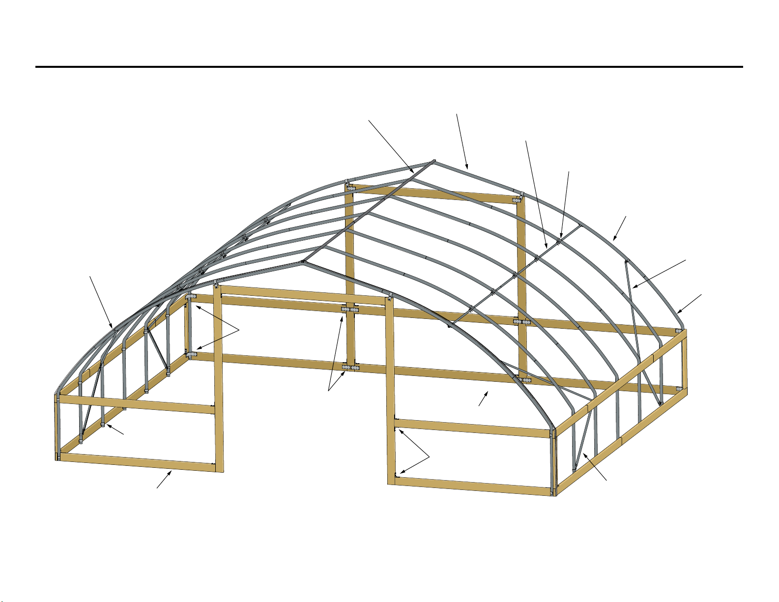
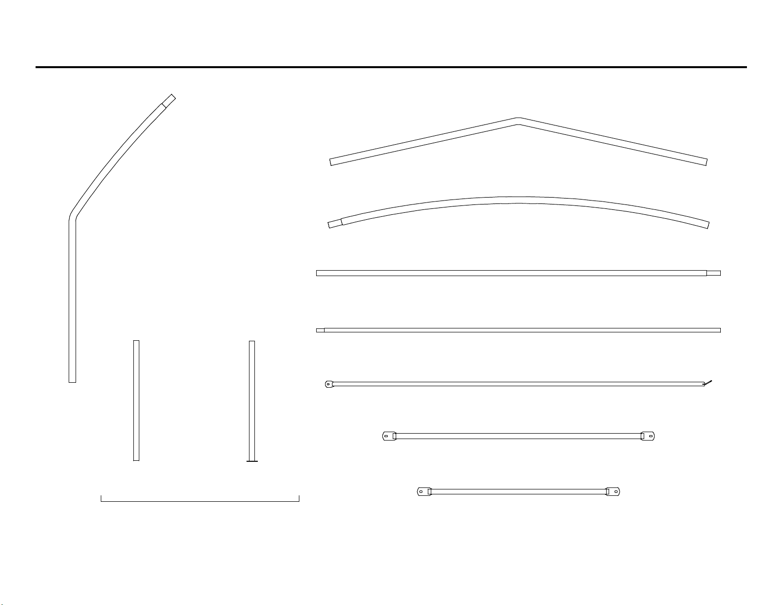
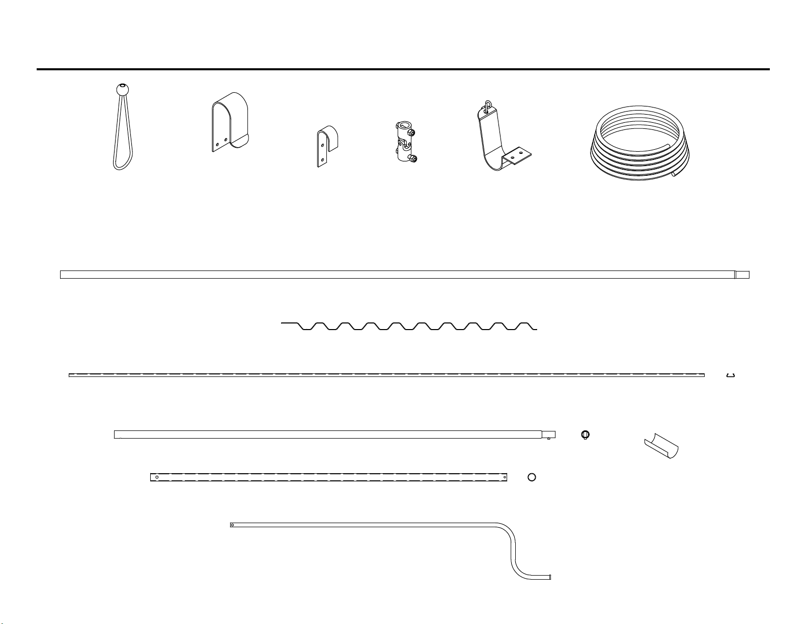
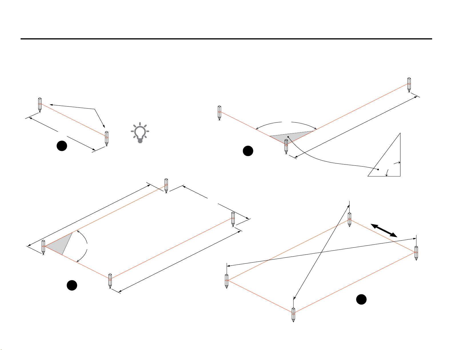
Overview of assembly procedure
DANGER
Do not overload structure.
WARNING
Do not walk on polycarbonate sheets.
Safety Guidelines
Poly-Tex does not warrant that this structure or foundation will comply with local or state
building codes. There is no guarantee of the load capacity of the structure for snow, wind,
seismic, or other loads unless buyer has received certified engineering drawings with the
structure, and Poly-Tex does not warrant that the frame or foundation will comply with
local or state building codes in buyer’s location.

4Limited Warranty

5Overview of FieldPro
Straight Side
Diagonal Brace
Flat Bracket
Corner
Bracket
2" U-Clamp
Wiggle Wire
Channel
Peak Brace
“L” Bracket
All Lumber
(by others)
Middle Section
Truss Purlin
Purlin Cross
Connector
Peak Section
Peak Brace
Peak Purlin
U-Channel

6Main Components Identification
RR2109
9-8R.F. U-Channel w/Swage
GS2401
Ground Stand 1.66 x 3
HP3546-HT
Straight Side (Gothic 30)
HP3547-HT Peak Section (Gothic 30)
HP3506 Diagonal Brace 78
(6 ft. spacing)
GS2400
Ground Stake
HP3505 Diagonal Brace 58
(4 ft. spacing)
HP3548-HT Middle Section (Gothic 30)
HP3503
HT Peak Brace 111
HP3340
9-8Truss Purlin w/Swage-Red
Customers will receive GS2400 or GS2401 depending on the type of installation.
See page 6 for installation options.

7Standard Fittings and Hardware
FT2108
1 1/2 UNIPipe clamp
FB2527
1 x 1 1/2 Rectangular
Black Plug
FT2570
Stop Tab
RS5000
1 1/4Round Black Plug
DR7032
Steel Corner Bracket
DR7033
Steel Flat Bracket
FT4040
Cross Connector
FT2079
Long Speed
Hook (2)
NB1832
5/16X 1 1/4
Carriage Bolt
NB1862
Lock Washer
NB1872
5/16 Hex Nut
FT2057
2 U-Clamp
FT2106
R.F. End Strap
HT1001
1.66 Driving Tool
BMS1130
18 Spike
FT2118
Spike Anchor
Bracket
NB1864
3/8
Lock Washer
NB1874
3/8
Hex Nut
NB1841
3/8 x 3
Carriage Bolt
FT1990
R.F. “L” Bracket
NB1809
1/4-14 x 1
Self-Drilling Screw
NB1807
1 1/2 Woodtite Screw
KH1000
Purlin
Fastener
NB1837
3/8 x 1 1/4 GRD5
Carriage Bolt
(For Optional Truss Package)

8Roll-Up Door and Roll-Up Curtain Components and Hardware
CF1014 - Tube w/Swage ( 116)
FT2071
Roll-Up Door
'J ' Hook
PT2521
10Bungee Ball
RC1007 - Roll-Up Tube Bottom 6- 2 1/4
RC1026 - Roll-Up Tube Bottom Extension 5
RC1303
U-Joint w/Bolts
RC1314
Roll-Up Crank (60)
RC1316
Roll-Up Door
Cradle
WIGGLWIRE - 43.000
Wiggle Wire
WWBASE9
8- 11Wiggle Wire Base
RC1010
Roll-Up Tube Clips
RC1330
Cradle, Short,
w/S-Hook
RS5049
1/4Nylon Rope 18600

9Building Site Layout
Dimension based on FieldPro length ordered
2
B = 4'
A = 3'
C = 5'
The 3:4:5 Triangle Method
90°
B = 4'
A = 3'
C = 5'
Masons line
B = 4'
A = 3'
C = 5'
3
Same dimension used in Step #2
Masons line
4
Both corner-to-corner
measurements should
be equal.
Adjust corner stakes
together until diagonals
are equal.
Tip:
An orange masons
line is easier to see.
2. Based on the length of the FieldPro you have ordered,
place a stake at point #3. Attach a masons line from Stake
#2 to stake #3. Use the 3 • 4 • 5 Triangle Method to square
up the corner at stake #2 to establish a 90° corner.
3. Place a stake at point #4. Attach a masons line from stake
#1 to stake #4. Use the 3 • 4 • 5 Triangle Method to square
up the corner at stake #1 to establish a 90° corner.
4. Attach a masons line from Stake #3 to Stake #4.
Make sure all lines are level.
Note: It is very important to accurately layout the building outline. It helps to
have someone assist you with laying out the building location.
1. Drive a temporary stake at point #1. Measure over 30and drive in another
stake at point #2. Attach a twisted masons line between stakes #1 and #2
approximately 12above ground. Use a line level to level the masons line.
30
#1
#1
#2
#2
#3
#3
#4
Temporary stakes
24Min.
Masons line
1
The “3:4:5 Triangle Method” of layout for a building produces a
perfect 90º corner as shown in the diagram. It forces your
foundation layout to be a perfect rectangle instead of a
parallelogram. The basic approach is to roughly layout your
string lines to the overall dimensions needed for whatever
size building. Then square-up one corner with a tape
measure using the 3:4:5 rule. Then move to any adjoining
corner to the first corner, and proceed the same way.
90°
90°
#1
#2
#3
#4
#1
#2
30
(verify)

10Layout of Ground Support Locations
4-0Typical (6-0Alternate)
Use corner to corner dimensions
to verify square layout

11Ground Stake Installation Options
Driven Ground Stake
Option #1
Average Soil and Wind Conditions
Ground Stand in Compacted Soil
Option #2
Moderate Soil and Wind Conditions
Ground Stake in Concrete Pier
Option #3
Special Soil and Wind Conditions
Per Local Codes
Ground Stake (GS2400)
Ground Stand
GS2401
Ground Stake
GS2400

12Ground Stake and Ground Stand Installation
Driving Tool
HT1001
Masons Line
Line level
4
8
12
Driven Ground Stake
Ground Stand in Compacted Soil
Ground Stake GS2400
Note:
If the top of the stake
becomes deformed
from driving in the stake,
cut o damaged
section from
top of stake.
Ground Stake GS2400 Preparation
Ground Stand GS2401 Preparation
Place a mark 8
from top of stake.
To save time, you can
prep all the stakes
ahead of time.
Install self-drilling
screws before driving
in the stake.
To save time, you can
prep all the stakes
ahead of time.
Same details
as Ground Stake
above
NB1809 1/4-14x1
Self-Drilling Screw
Masons Line
Ground Stand
GS2401
6Min. hole
Compacted Fill
Ground stakes are driven
into the ground using the
Driving Tool (HT1001) until
the top of the ground
stake is 12above the soil
line.
A masons (twisted) line is
attached between all four
corner stakes 8from the
top of stakes. Use a line
level to line up all the
stakes at the 8mark.
For longer structures, the
masons line may need to
be supported every 50
to prevent sagging. Sight
down the line visually to
check the straightness of
the line.
Ground stands are
placed into a 6diameter
(min.) hole. The top of the
ground stand will be 12
above the soil line.
Ensure that the ground
stands remain plumb
while compacting the soil
all around.
A masons (twisted) line is
attached between all four
corner stakes 8from the
top of stakes. Use a line
level to line up all the
stakes at the 8mark.
For longer structures, the
masons line may need to
be supported every 50
to prevent sagging. Sight
down the line visually to
check the straightness of
the line.
Line level
4
8
12

13Ground Stake Installation in Concrete Pier
Masons Line
12
Maximum
Ground Stake (GS2400)
Top of
Footing
Depth of Footing
to Conform to
Local Building Codes.
Provide 27Minimum
12Minimum
4Minimum Side Cover
3Minimum Bottom Cover
Ground Stake in Concrete Pier
To save time, you can
prep all the stakes
ahead of time.
Ground Stake,
Footing Centerline
Line level
44
66
Ground Stake GS2400 Preparation
Place a mark 6
from top of stake.
Install 1 self-drilling
screw in the stake.
NB1809 1/4-14x1
Self-Drilling Screw
Steps

14
Mid-Section HP3548
Place mark here
Straight Side
HP3546
50 3/16
Nominal
Dimensions
2
1
NB1809
Two, (2) 1/4-14x1
Self-Drilling Screws
Detail A
Detail B
Detail C
Straight Side HP3546 Mid-Sec-
tion HP3548
Straight Side HP3546
Mid-Section HP3548.
1/4-14 X 1Self-drilling Screws (NB1809)
CAUTION: Do not Install the self-drilling
screws so that the heads of the screws face
upwards. Doing so will allow the screw heads
to come in contact with the Poly Sheeting
Cover causing damage to the Poly Cover
Building Side Sub-Assembly
1
2
3

15Building Main Frame Sections
Side Assembly Side Assembly
Mark
Note: Be sure you have marked
each side assembly for the future
location of the Purlin and Purlin Fastener.
50 3/16
Peak Section
HP3547
Nominal
Dimensions 2
1
NB1809
Detail A
Detail B
Two, (2) 1/4-14x1
Self-Drilling Screws
Peak Section
(HP3547
1/4-14 X 1Self-drilling Screws (NB1809
CAUTION: Do not Install the self-drilling screws
so that the heads of the screws face upwards.
Doing so will allow the screw heads to come in
contact with the Poly Sheeting Cover causing
damage to the Poly Cover.
1
2

16Erecting Initial Frame Sections
1/4-14 x 1
Self Drilling Screws
(NB1809)
10
Leveling Screw
Ground Stake
Ground Stakes
1
Detail A
Frame #3
Frame #2
End Frame
Slide first three frame sections over the ground
stakes until they rest on the leveling screws
previously installed in each ground stake.
Use temporary wood bracing if necessary.
2Fasten the frame sections to the ground stakes
using two, (2) 1/4-14 x 1Self-drilling Screws.
See Detail A.

17Adding Diagonal Braces
‘X’
‘X’
‘Y’
‘Y’ Frame #3
Frame #2
End Frame
Detail B
Detail A
Detail C
Note: The brace connection a ‘Y’
may seem misaligned with the
speed hook. However, when the
hardware is tightened and
everything pulls together, this
“temporary misalignment” will
not be an issue.
Plumb
Plumb
Top of
Speed Hook
4 ft. on center frame spacing
6 ft. on center frame spacing
Diagonal Brace 58
HP3505
43½
HT Peak Brace 111
HP3503
44
‘Y’
Top of
Speed Hook
Diagonal Brace 58
HP3505
43½
HT Peak Brace 111
HP3503
66
‘Y’
‘X’
‘X’
1
3
2
Attach HT Peak Brace (HP3503) between points
‘X’ and ‘Y’. The angled end of the Brace attaches
at point ‘X’. You will need a Speed Hook (FT2079)
to attach the Brace to the End Frame using
carriage bolts/washer/nut. See Detail C. Check to
see that frame sections are plumb and then final
tighten all hardware.
After all the Main Frames and Purlins have been
erected, Steps 1–3 will be repeated to attach
Diagonal and Peak Braces to the other end of
the structure.
Important: Make sure screws and ends of carriage
bolts do not face outwards to avoid damage to
poly covering. All components attached to Long
Speed Hooks must be mounted
on the outside of the tabs.
NEVER install any components
between the tabs.
IMPORTANT: Play it safe when
working at heights. Scaolding
is preferred when installing
higher components. Use a
helper when necessary.
DANGER
Note: The Main Frames can be installed on
4 foot or 6 foot centers. The drawings at the lower
right show where to place the Diagonal Braces.
Attach a Speed Hook (FT2079) to Frame #3 at point
‘X’ at a height of 43-1/2. See drawings below.
Attach another Speed Hook near the bottom
of Frame #2. Attach the (specified) Diagonal Brace
between these two Speed Hooks. Use a carriage
bolt, lock washer, and hex nut to attach the
Diagonal
Brace
. Do not fully tighten at this time.
Final adjustment may be required after the Peak
Brace has been installed. See Details A & B. 5/16X 1 1/4
Carriage Bolt
NB1832
5/16 Lock Washer 5/16 Hex Nut
NB1862 NB1872

18Side Purlin Installation
Cross Connector (FT4040
Cross Connectors
Cross
Connectors
Truss Purlin (HP3340) Cross Connectors
End FramePurlinEnd Frame Purlin
Fastener (KH1000) 1/4-14 X 1Self-drilling Screws (NB1809.
Round Plastic Plug (RS5000) Purlin
12
Mark
50
50
Frame #3Frame #2End Frame
View A looking
up at Purlins
View A
Cross Connector FT4040
(hardware included)
Truss Purlin
HP3340
Round Black Plug
RS5000
Purlin Fastener
KH1000
Detail A
1/4-14 x 1
Self Drilling Screws
(NB1809)

19Adding Main Frames and Extending Side Purlins
Main Frames
Truss Purlins (HP3340) as
End Frame
Cross Braces
Truss Purlin
Truss Purlin
Purlin using Cross Connectors (FT4040)
1/4-14 X 1Self-drilling Screw (NB1809
Purlin
PurlinEnd Frame
1/4-14 X 1Self-drilling Screws (NB1809) Purlin
Fastener (KH1000) Purlin
Round Black Plug (RS5000) Purlin
1
End Frame
Purlin Fastener
KH1000
Cut o Purlin
end flush and
add Black Plug
RS5000
Detail A Detail B
Truss Purlin
HP3340
1
1/4-14 x 1
Self Drilling Screw
(NB1809)
50
Cross Connector FT4040
(hardware included)
2
4
3

20Peak Purlin Installation – Part 1
Peak Purlin
RR2109
1/4-14 x 1
Self Drilling Screw
(NB1809)
Intermediate Frames
End Frame
R.F. End Strap
FT2106
1x 1-1/2Rectangular
Black Plug FB2527
1-1/2Uni Pipe Clamp
FT2108
(hardware included)
Stop Tab FT2570
Peak Purlin End
Detail A
Detail B
Stop Tab (FT2570)
Peak Purlin (RR2109)
End Strap (FT2106) onto
Stop Tab
5/16 Hex Nut (NB1872) 5/16 Lock Washer
(NB1862).
End Strap
1/4-14 x 1 Self Drilling Screw
(NB1809). Rectangular Black Plug
(FB2527) Peak Purlin
Uni Pipe Clamp (FT2108) Peak
Purlin Main Frame
Uni Clamp Purlin
Uni Clamp Main
Frame .
123
Table of contents
Other Poly-Tex Greenhouse Kit manuals
Popular Greenhouse Kit manuals by other brands

Growers SOLUTION
Growers SOLUTION SUPER-DUTY Installation

Halls
Halls QUBE 66 manual

ClearSpan
ClearSpan 104903 Assembly instructions

Gainsborough
Gainsborough K164 Assembly instructions/Instructions for use

FJK home products
FJK home products HD70401 Assembly instruction

Vitavia
Vitavia Triton 5000 quick start guide

Dancover
Dancover GH140055 manual

One Stop Gardens
One Stop Gardens 97439 Setup and maintenance instructions

G-Tools
G-Tools G-kit Bonanza 1m2 manual

GrainPro
GrainPro MA4040RAD0914-10 instruction manual

Baux Industries
Baux Industries GROW KIT 2 ft x 4 ft Assembly instructions

Palram
Palram Americana 12'x12' Hybrid Glazing Assembly instructions