The one
that
creates a
new
trend
AnyShop II
Precaution
e Warranty
We
guarantee our
POS
terminal product
and
its parts against defects
in
materials
and
workmanship under proper
use
for a standard period
of
2years from the date of
original purchase.
During this period,
we
will
repair or replace defected and/or faulty products or parts
without imposing a charge for spare
and
labor
to
the purchaser.
The
1st year includes servicing
and
new or refurbished replacement parts free of
charge, with one-way shipping cost born
by
the seller; the customer shall
be
responsible for return delivery charge.
The
2nd
year also includes free of charge servicing
and
parts, but a limited warranty
requires the entire shipping cost
be
borne
by
the customer.
Products out of the warranty period or scope shall
be
diagnosed at customer's
expense.
We
will
charge for repair
and
delivery
in
the
case
of damage
as
a result
of
the customer's mistake, abnormal usage, carelessness or natural disasters.
e Notice
for
safety
1.
We
recommend using proper power voltage
as
a precaution against fire
and
electrical shock.
2.
Avoid
exposing
the
product
to
direct sunlight
and
do
not
use
the product near areas
of high moisture ; this may cause low reliability and/or operational malfunction.
3.
Be
aware of electro-static
on
PCB
of system with anti-static appliance; This is a
possible cause of low reliability
and
short life term.
4. Place a product
away
from highly static areas; this may lead
to
low performance
and
a reduced life cycle.
5.
Do
not disturb metal material or obstacle
in
product
in
danger
of
fire
and
electric
shock.
6.
Use
product
in
simple power cord plug-in circumstance
in
caution
of
fire, electric
shock
and
system disorder
on
electricity.
7.
Be
careful of other electronics with possible high frequency, electronic
and
magnetic affects
lEx.
Audio,
Electronic-range, etc]; there
is
a strong possibility this
will
lead
to
the product becoming out-of-order or system
error
.
8. Risk of explosion if battery is replaced incorrectly; dispose of
used
batteries
according
to
the instructions.
9.
Only
use
adapter supplied.
If
an
incorrect adapter is not used, the product's performance may decrease
and
there
is
an
increased risk of fire or electric shock.
1.
Package contents
The
following
items
are
included
when
you
purchase
this
product.
If
any
of
these
items
are
damaged
or
missing,
contact
your
dealer
for
assistance.
An
yS
hop
II
2.
Configuration
[Front View]
chLCD &
lou
panel displ
LAN LED
HOD
LED
Power LE
ay
D
Dual
sp
eaker
o----
[Side View]
[1/0 View]
ITI
§ I
~
...
----------""
O<>
Dri
vers
CD Use
r"
s
ma
nual
Ad
apte
r Power co rd
~
~
I
Dallas !-button
reader
II
IH
"'
~
•
~
M
~
5
~;;.'
agnetic
stripe
reader
(MSR)
mart card
reader
(SCR)
Power switch
~~~
---------
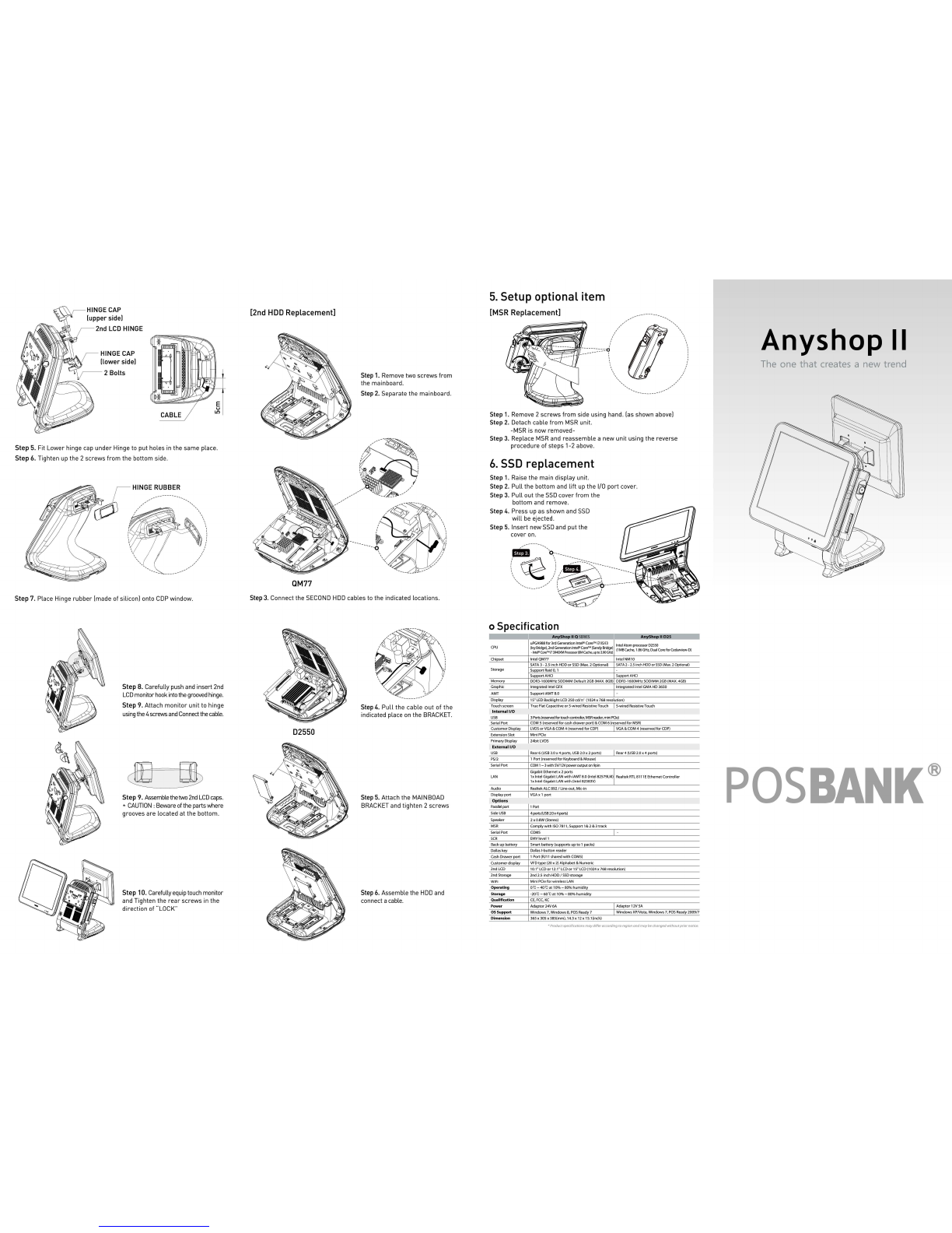
Step
1.
Raise
the
main
display
unit.
Step
2.
Pull
the
bottom
and
lift
up
the
1/0
port
cover.
[1/0 port ;
Q]
*
1/0
ports
may
differ
according
to
product
model
or
options.
1
2
3
4
~
o\'"
-----c
®
=---...Jo
@)
LPT
Description
LPT port
Cash
drawer
port (option)
Power
connector
PS/2 connector
[1/0 port ; 025]
Descripti
on
1 Cash
drawer
port (opti
on)
2 Power conn ect
or
3 PS/2 connector
4 U
SB
2 port
3.
Power
on
@)
o
(ID
o
o
(ID
o
~
~.:0
o
oo
o
o
oo
o[
~
J
C®J
::
COM2
VGA
Description
5
COM1. COM2.
COM3
port
6
VGA
port
7 LAN port
8 U
SB
2 port
o
(ID
o
o(
®
)o
l(?5l
a
COM1
COM3
~
o
(ID
o
o(
®
)o
~
::
COM2 VGA
Description
5
COM1. COM2.
COM3
port
6
VGA
port
7
LAN
port
The
power
switch
is
located
right
hand
side
of
the
main
body
under
the
display
unit.
When
connected
to
power
source,
the
POWER LED
will
be
lighted-on
automatically.
The
unit's
status
can
be
determined
by
each
LED
lamp.
-
~
'
...
...
"!"
...
--~'
a=l
h
ll:-i
Indicator
modes
are
as
follows;
~~
:;iE§§
~~~
~
When
co
nn
ec
ted
LAN
: LAN
LED
is
bli
n
king
[Y
ellow]
Ope
ra
ti
on
mo
d
e:
HOD
LED
is
blinking
[Red]
PO
W
ER
LED
is lit
[Gr
ee
n]
4.
Option devices
Connect
the
hinge
and
COP
or
2nd
display
monitor,
after
connecting
the
main
body
and
cable
.
Turn
off
power,
and
then
turn
on
again
to
boot
up
.
Check
if
the
start
-up
screen
appears
normally.
[Connect
the
COP
to
COM4.)
Caution:
Completely
remove
the
power
cord
before
removing
or
installing
a COP
or
a
2nd
display
monitor.
[Customer display]
Step
1. Separating
LCD
monitor
module.
Step
2. Separating Back cover.
[2nd Display]
0 0 0 0
~-
~
j l
\.
~
··
..
.
....
.
....
...
..
.
....
..
..
....
.
..
.
..
.
...
..
...
..
......
.
·
·~
Step
3.
Remove
the 2screws
used
for
clamping
COP
.
Step
4. Separate
the
COP
Bracket
after
removing 2 screws.
The
assembling
method
of
the
2nd Display is
equal
for
all
the
products.
[10.1, 12.1,15 inch]
Step
1. Lay the main body
on
the
side
in
order
to
place the hinge
on
the
correct
position.
Step
2. Fasten the 4 screws onto
second
monitor
hinge, and then
connect it to Main body unit.
Step
3. Put the main body back,
and assemble the hinge until
you
see
it
coming
out
of
the
BACK
COVER
COP
window.
Step
4. Put Back cover and Main
body
unit together
by
tightening
up
the 2 screws.