Powermania Turbo MV2 Series User manual

Model # 12V Output Max. Output Battery System (DC)
12V 24V 36V 48V
Turbo M212V2 2 12 Amps
Turbo M220V2 2 20 Amps
Turbo M320V2 3 20 Amps
Turbo M230V2 2 30 Amps
Turbo M330V2 3 30 Amps
Turbo M430V2 4 30 Amps
Turbo M240V2 2 40 Amps
Turbo M340V2 3 40 Amps
Turbo M440V2 4 40 Amps
Turbo MV2 series battery charger
Operation Manual
R

1www.powermaniausa.com
Important Notice
This manual contains important safety, operation, and installation instructions. Please read all
instructions before using your Powermania Turbo MV2 onboard battery charger.
This charger is designed to charge only Lead Acid type 12V DC batteries; Flooded Lead-Acid,
AGM (Absorbent Glass Mat), and GEL (Gelled Electrolyte Lead-Acid). Use of this product to
charge other types of batteries may cause batteries to burst and result in personal injuries. If
you are unsure about the type of battery, please consult with battery manufacturers.
WARNING:
Working in the vicinity of lead acid batteries is dangerous. Batteries generate explosive
gases during normal operation. For this reason it is extremely important to follow the safety
instructions each time you use the charger.
Do NOT use the charger with a 2-pin AC adapter or extension cord. Do NOT cut or make
any modification to the factory equipped AC power cord. Doing so can result in serious
personal injury.
DO NOT USE 2-PIN AC ADAPTER/EXTENSION
CORD
The charger MUST ONLY be connected to a properly grounded AC outlet that is protected
by Ground Fault Circuit Interrupter (GFCI) breaker.
CONNECT ONLY TO PROPERLY GROUNDED
OUTLET
The AC power cord MUST be UNPLUGGED from the outlet BEFORE connecting any DC
wires to the batteries or making any DC wiring connection change. Failure to do so may
cause electrical shock resulting in serious personal injury or death.
WARNING:
CHECK BATTERY TYPE
RISK OF EXPLOSIVE GASES!
WARNING:
CAUTION:
DANGER: ALWAYS UNPLUG AC POWER CORD BEFORE
MAKING ANY DC WIRING CONNECTION

2
www.powermaniausa.com
Contents
Introduction ................................................................................................................ ....3
Personal safety precautions...........................................................................................3
Precautions prior to charge battery ...............................................................................3
Box contents...................................................................................................................4
Specifications.................................................................................................................5
Feature Highlights ..........................................................................................................8
Installing the charger....................................................................................................10
Installation Drawing...................................................................................................... 11
Select battery type .......................................................................................................12
Connect the DC cables................................................................................................ 13
Operating the charger.................................................................................................. 17
LED indicator descriptions........................................................................................... 17
Troubleshooting............................................................................................................18
Troubleshooting - Battery Isolation Test.......................................................................19
Maintaining the charger ............................................................................................... 19
Fuse replacement instruction.......................................................................................20
Warranty and service information ................................................................................21
Contact information ......................................................................................................21
Optional Accessories ...................................................................................................21
Warranty card...............................................................................................................22

3www.powermaniausa.com
Introduction
Thank you and congratulations on your new purchase of the Powermania Turbo MV2 series
onboard battery charger. This charger is waterproof, corrosion-resistant and shock-resistant—
ideal for recharging and maintaining 12V DC batteries in various marine applications and other
harsh environments.
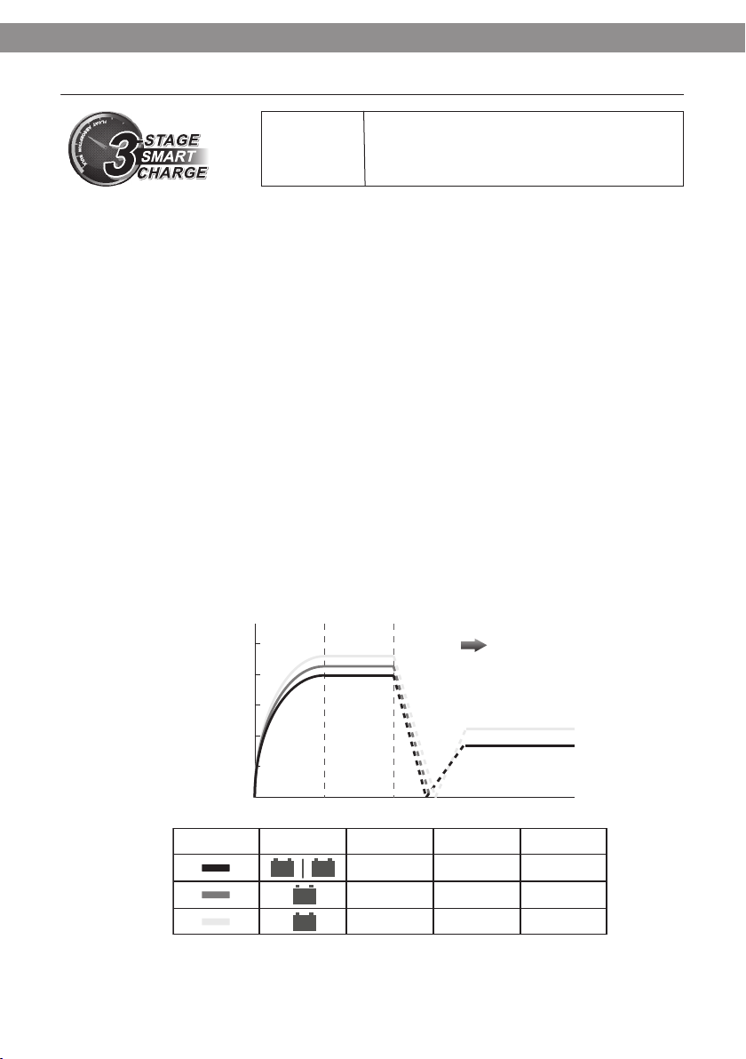
Featuring Automatic 3-Stage Smart Charge and Battery Selector, this charger is designed to
charge and maintain various types of 12V DC batteries using full automation. Our charging
process has been proven to bring out the batteries’ full potential after each charging
session while also extending the batteries’ lifespan at the same time.
The Turbo MV2 also comes equipped with extensive safety features and intuitive LED indicators
to help protect your investment. Please visit our website www.powermaniausa.com for the latest
product updates and information.
1. Someone should be within range of your voice or close enough to come to your aid when
working near a Lead-acid battery.
2. Always work in a well-ventilated area away from ignition sources.
3. Have plenty of fresh water and soap nearby in case battery acid comes in contact with
skin, clothes, or eyes.
4. Wear complete eye protection and protective clothing. Avoid touching your eyes while
working near batteries.
5. If battery acid contacts your skin or clothing, wash them immediately with soap and water.
If acid enters eyes, immediately flood the eyes with running cold water for at least ten (10)
minutes and get medical attention.
6. Never smoke or allow an open flame near batteries.
7. Do not drop any type of metal tool onto battery terminals as that may cause a spark or
short-circuit which may result in an explosion or fire.
8. Remove all personal metal items such as rings, bracelets, necklaces, and watches when
working near batteries. A battery can cause short circuit currents that are high enough to
weld metals and cause serious burns.
INTRODUCTION
• Do not charge outside of battery manufacturer’s recommended temperature conditions.
• Do not use this charger to charge dry cell batteries for home appliances.
• Do not operate the charger if any of the prewired cables or LED’s are damaged.
• Make sure all onboard connected electronic devices are powered off.
• If a battery needs to be removed from the vehicle or boat to be charged, always remove the
PERSONAL SAFETY PRECAUTIONS
PRECAUTIONS PRIOR TO CHARGING BATTERY

4
www.powermaniausa.com
Safety Precautions
grounded negative terminal from the battery first.
• Be sure to have enough open space around the battery for good ventilation during charge.
Gas fumes can be vented abd blown away by using a piece of cardboard or other non-
metallic material as a fan.
• Wear full eye protection when cleaning battery terminals to prevent corrosive materials from
getting in contact with eyes.
• Add distilled water in each cell until battery acid reaches levels specified by battery manu-
facturer. Do not overfill. For batteries without cell caps, follow the recharging instructions
provided by battery manufacturers.
• If necessary, use only industrial grade, UL approved extension cord that connects to the
charger. When using an extension cord, connect the charger end first before you plug the
extension cord to a power outlet. When unplugging, unplug the end connecting to power
outlet first, and then unplug the end connects to the charger.
• Make sure the AC power outlet you are connecting the charger to is GFCI (Ground Fault
Circuit Interrupt) protected.
BOX CONTENTS
• Turbo MV2 series charger prewired with one AC power cord and DC output cables
• Operation manual / Registration card
• 4 installation screws
• 4 Raiser Footing Spacers

5www.powermaniausa.com
Specifications
M212V2 M220V2 M320V2 M230V2
Manufacturer’s P/N 58201 58203 58204 58205
Max. Input
Current (@120V AC) 1.7 Amps 2.7 Amps 2.7 Amps 5.9 Amps
# 12V Output
(Prewired) 2 2 3 2
Maximum
Output 12 Amps 20 Amps 20 Amps 30 Amps
Output Voltage
Configuration 12/24V DC 12/24V DC 12/24/36V DC 12/24V DC
Weight 6.5 lb. 7.7 lb. 8.2 lb. 13.0 lb.
Dimension
(Inch)
81/4x 53/4x
23/4
81/4x 53/4x
23/4
81/4x 53/4x
23/4
103/4x 7 x 31/4
Cooling Fan No Yes Yes Yes
SPECIFICATIONS

6
www.powermaniausa.com
M212V2 M220V2 M320V2 M230V2
Manufacturer’s P/N 58201 58203 58204 58205
Max. Input
Current (@120V AC) 1.7 Amps 2.7 Amps 2.7 Amps 5.9 Amps
# 12V Output
(Prewired) 2 2 3 2
Maximum
Output 12 Amps 20 Amps 20 Amps 30 Amps
Output Voltage
Configuration 12/24V DC 12/24V DC 12/24/36V DC 12/24V DC
Weight 6.5 lb. 7.7 lb. 8.2 lb. 13.0 lb.
Dimension
(Inch)
81/4x 53/4x
23/4
81/4x 53/4x
23/4
81/4x 53/4x
23/4
103/4x 7 x 31/4
Cooling Fan No Yes Yes Yes
M330V2 M430V2 M240V2 M340V2 M440V2
58206 58207 58208 58209 58210
5.9 Amps 5.9 Amps 7.2 Amps 7.2 Amps 7.2 Amps
3 4 2 3 4
30 Amps 30 Amps 40 Amps 40 Amps 40 Amps
12/24/36V DC 12/24/36/48V
DC 12/24V DC 12/24/36V DC 12/24/36/48V
DC
13.5 lb. 14.0 lb. 13.5 lb. 14.0 lb. 14.5 lb.
103/4x 7 x 31/4103/4x 7 x 31/4103/4x 7 x 31/4103/4x 7 x 31/4103/4x 7 x 31/4
Yes Yes Yes Yes Yes

7www.powermaniausa.com
Specification (All models)
Input voltage: 120/240V AC
Input frequency: 50/60Hz
Oututput voltage: 13.4V ~ 14.8V DC
Battery type setting: 1. Flooded (Lead-Acid) / AGM
2. 14.6 CV (Constant Voltage)
3. AGM+
Max. Absorption time: 3 hours
Output cable length: 6 feet / 182 cm
Power cord length: 6 feet / 182 cm
LED indicators (top): 1. Power
2. Monitor On
3. Float Charge On
4. Error
5. AGM+ charge mode
6. 14.6 CV charge mode
7. Flooded (Lead-Acid) / AGM charge mode
LED indicators (bottom): Charge status / DC connection check
Feature highlights: Adaptive Loading
3-Stage Smart Charge
Battery Type Selector
Safety features: Ignition Protection
Overheat Protection
Over-Current Protection
Over-Voltage Protection
Reverse Polarity Protection
Short Circuit Protection
Design standard & Compliances: FCC Part 15 Class A
IP65 (Splash-proof)
Marine UL 1236
CSA C22.2 No. 107.2
California Energy Commission (CEC)
SPECIFICATIONS (All models)

8
www.powermaniausa.com
Feature Highlights
FEATURE HIGHLIGHT: Adaptive Loading
The Adaptive Loading feature adjusts the charger’s output level automatically and dynamically
on each output bank. This allows more charging power goes to the more depleted battery and
less power goes to the battery that is closer to full charge.
In Scenario 1 (left chart), the two batteries have similar state of charge. The Turbo MV2 allocates
approximately even 50% of it total output to each battery. In Scenario 2 (right chart), the first
battery’s is close to full charge, but the second battery is deeply depleted. In this case, Adap-
tive Loading allocates 10% of it charging amperage to the first battery and the rest 90%* to the
discharged one.
Note that in both scenarios the charger uses its full output - maximum amperage, unlike char-
gers with fixed output-per-bank, the Turbo MV2 charges all connected batteries in the shortest
time possible.
* Due to safety precautions, the maximum current is limited to 25 Amp per output.
USER
BENEFIT:
Fully charges all connected batteries in
the shortest time.
50%
50%
10%
90%

9www.powermaniausa.com
Feature Highlights
battery’s from self discharge.
At the first stage (Bulk), the charger provides its maximum constant current for fast charging.
The battery’s voltage increases as it absorbs the charge. When the battery voltage reaches
14.5V (Lead Acid /AGM mode), it’s approximately 85% recharged. The charger then moves to
the second stage.
At the second stage (Absorption), the charger continues to charge the battery at 14.5V (Lead
Acid / AGM mode). The charging current drops as the battery charged up to 100%. When the
battery is fully charged, the charger then moves to the third stage.
At the third stage (Monitor / Float), the charger first goes to idle (no float charge) while monitors
the batteries’ state of charge. If the voltage of battery #1 (battery connected by output #1) falls
below 12.5V, the charger restarts a new charge cycle. After a set idle period, the charger be-
gins to apply float voltage at 13.4V (Lead Acid / AGM mode), and continues to monitor. It is safe
to keep the charger connected to the battery indefinitely to maintain the battery’s full charge.
Turbo MV2 charges a battery in three sequential stages: Bulk, Absorption, and Monitor / Float.
This method is proven to bring a battery to its fullest charge, as well as maintain a fully charged
FEATURE HIGHLIGHT: 3-Stage Smart Charge
USER
BENEFIT:
Maximizes battery potential and pro-
longs battery life.
* 14.6 CV Mode is designed for recharging LiFePO4 (Lithium Iron Phosphate) batteries. Please consult
battery manufacturer for compatibility.
** AGM+ Mode is designed for recharging TTPL (Thin Plate Pure Lead) AGM batteries. This charging profile has
been approved by Odyssey and NorthStar battery company.
Battery Voltage (V DC)
Absorption Float & Monitor
15
14.5
14
13.5
13
Bulk Full Charge
& Monitor
Lead-Acid /AGM
14.6 Const. Voltage*
AGM+**
14.5 V DC
14.6 V DC
14.7 V DC
13.4 V DC
0 V DC
13.6 V DC
Charge Mode Voltage
(Absorption)
Voltage
(Float)
Line LED
AGML. Acd
AGM+
14.6
CV

10
www.powermaniausa.com
Installation
The Powermania Turbo MV2 series charger is designed to be mounted onboard a vehicle or
watercraft. The chart below shows the proper orientation of the mounting position. The top
row LED lights line up horizontally at the top and the output cables at the bottom of the charger.
This orientation optimises air ventilation during operation. Follow these instructions for a proper
charger installation:
1. Select a well-ventilated area where there are at least 8 inches of clear air space around the
charger.
2. Make sure the charger’s DC output cables can reach all batteries from the mounting loca-
tion.
3. If the DC cables are not long enough, they may be extended by adding Powermania tool-
free DC extension kit (available in 5’, 10’, or 15’ length) - Accessory P/N 10521 (5’), 10522
(10’), and 10523 (15’). If the wires are to be cut and connected to a third party extension
cable, use marine grade 12 AWG for 12 Amp and 20 Amp models, and 10 AWG for 30 Amp
and 40 Amp wires. Each splice should be covered by adhesive lined / dual wall heat shrink
tube to prevent corrosion at the joints. The splicing should be made between the fork of
the cable and the fuse holder so that the fuse stays within 6” of the battery terminals. Do
not add more than 15’ of DC cable extension. Making any modification to the factory-
equipped cables will void the warranty.
4. Do not mount the charger directly on carpeted, upholstered, or varnished surfaces. If the
charger is to be mounted on these surfaces, it is mandatory to use the included Raiser
Footing (or the optional Flange Footing) to raise the charger bottom from direct contact of
the mounting surface.
5. Make sure the mounting surface can firmly support the charger with the provided screws.
If through bolt mounting is desired, use optional Flange Footing accessory and mount the
charger using #10 bolts and nuts.
6. Support the charger and position it on the tentative mounting area. Use a pencil to mark
position of each mounting hole.
7. Use 1/8” drill bit to drill on the marked position.
8. Align the charger to the drilled holes, and then secure the charger with the four provided
screws.
INSTALLING THE CHARGER

11 www.powermaniausa.com
Installation
INSTALLATION DRAWING
8 inch
8 inch
8 inch
8 inch
Raiser Footing
Raiser
Footing
Raiser
Footing
Optional Flange Footing
Accessory P/N 10511
INSTALLATION DRAWING (OPTIONAL FLANGE FOOTING)

12
www.powermaniausa.com
Select Battery Type
SELECT BATTERY TYPE
The Battery Selector’s tip point can be switched in three positions: Refer to the following illustra-
tion. From left to right, the first position (factory setting) is for charging Flooded Lead-Acid type
and most generic brand AGM batteries. The middle position is for charging Lithium Iron Phos-
phate (LiFePO4) batteries, and the right position (AGM+) is for charging Thin Plate Pure Lead
(TPPL) AGM battery (Odyssey and Northstar AGM’s).
To switch to a different charge mode:
1. Make sure the charger’s power cord is
unplugged from the power outlet.
2. Loosen the screws from the battery selector.
3. Carefully pull the battery selector straight out
from the charger.
4. Place the battery selector back to the char-
ger with the desired battery type position.
5. Secure the screws back to the battery
selector.
Do NOT use any other screws that are not provided by Powermania to tighten the selector cap.
Using unauthorized screws could damage the charger and result in serious personal injury.
RISK OF PERSONAL INJURYCAUTION:
AGM+
AGM
L. Acd 14.6
CV

13 www.powermaniausa.com
DC Wiring Connection
CONNECT THE DC CABLES
The following pages demonstrate proper DC wiring configurations for Powermania Turbo MV2
series chargers. When making DC connections, make sure each set of positive and negative
connectors are connected to the same 12V battery. The red wires are positive (shown as grey
color on the diagrams) and the black ones are negative. Never connect a black wire (negative)
to a terminal that is connected with a red wire (positive).
ALL charger’s output cables must be connected to battery. Never leave any output uncon-
nected. If there is a spare output left unused, double up the spare output to a 12V battery that’s
already been connected by another output.
It is recommend to connect the charger’s first output (output 1) to main house battery, or
the battery that’s typically got most depleted. The first output set is located next to the AC
cord.
Please refer to the connector legend reference diagram which is used for all of the connection
diagrams:
EACH AND EVERY DC OUTPUT CABLE MUST BE CONNECTED TO A 12V
BATTERY FOR PROPER OPERATION.

14
DC wiring connections
Connecting a dual output charger to two serial-connected 12V batteries.
www.powermaniausa.com
Connecting a dual output charger to two parallel-connected 12V batteries.
Output 1
Output 2
Connect both sets of DC outputs
to the same battery’s terminal. DO
NOT LEAVE ANY SPARE OUTPUT
UNCONNECTED.
If a 12V system is composed of two
6V batteries, connect the output’s
positive terminal ring to battery
#1’s positive terminal and the same
output’s negative ring terminal to
battery #2’s negative terminal.
Output 1
6V 6V
12V
output
12V

15 www.powermaniausa.com
DC wiring connections
Connecting a dual output charger to two parallel-connected 12V batteries
Connecting a dual output charger to two serial-connected 12V batteries (24V system)
Connect each set of output to each
12V battery. The jumper can be left
connected between the two batter-
ies during charging.
Connect one set of output to each
12V battery. The jumper can be left
connected between the two batter-
ies during charging.
Output 1
Output 2
Output 1
Output 2
12V 12V
12V 12V

16
www.powermaniausa.com
Connecting a quad output charger to four 12V batteries
Connecting a triple or quad output charger to three 12V batteries
DC wiring connections
Output 3
Output 2
Output 1
The batteries could be independent,
serial-connected or parallel-con-
nected. If connecting a quad output
charger to three 12V batteries,
connect the spare output to any one
of the three (preferably the weakest)
batteries.
Output 3
Output 4
Output 2
Output 1
The batteries could be independent,
serial-connected, parallel-connect-
ed, or mix-and-matched.

17 www.powermaniausa.com
Operating instructions
OPERATING THE CHARGER
1. Install the charger and make appropriate DC wiring connections as per the wiring dia-
grams.
2. Choose an appropriate setting on the Battery Selector (page 12).
3. Plug in AC power cord to properly grounded outlet.
4. The Power indicator LED will display green, indicating the presence of AC power.
5. The charger will go through a brief test cycle if all the DC outputs are properly connected to
a 12V bank.
6. The charger will start a new charge cycle on the outputs that have proper DC connections.
7. For models equipped with a cooling fan, the fan could be turned on and off automatically
based on the ambient and charger’s temperature.
8. When a recharge cycle is completed, the charger will go into monitor mode and then later
continue to charge the batteries at float voltage. It is safe to leave the charger’s power on
and connected to the batteries indefinitely. If the battery loses charge from use, the char-
ger will start a new recharge cycle.
Icon Indicator Description
Power Power on
Monitor On Monitor mode on
Float On Float Charge on
(No Float charge if 14.6 CV Mode is selected)
Error Error. Proceed to Troubleshooting
AGM+ Charge Mode AGM+ Charge Mode
(for Odyssey & Northstar TPPL AGM batteries)
14.6 CV Charge Mode 14.6 CV Charging Mode
(for Lithium Iron Phosphate - LiFePO4)
Flood lead-acid & AGM
Charge Mode
Flood lead-acid & AGM Charge Mode
(for most brand’s lead-acid / AGM batteries)
Charge Status /
Connection Check
Red: Charging
Green: Ready
Amber: DC connection fault
LED INDICATOR DESCRIPTION
AGM+
L. Acd AGM

18
www.powermaniausa.com
Troubleshooting
TROUBLESHOOTING
DANGER:
ALWAYS DISCONNECT AC POWER CORD PRIOR
TO MAKING ANY DC WIRING CONNECTION
CHANGE OR WHEN CHECKING FUSES.
Problem Possible Cause Solution
No LED On No AC input
Check AC input connection. Try with a dif-
ferent AC outlet to make sure AC power is
present.
Error LED On
Charger detects
battery voltage
exceeds safe range
for one or more
outputs
Check and correct battery wiring connec-
tion. (Refer to wiring connection charts.)
Make sure each output is connected to one
12V battery. Wait at least 30 seconds before
plugging in AC power again.
If Error LED continues to be on after wiring
correction, conduct Battery Isolation Test
(page 19).
Charger or ambient
temperature ex-
ceeds safe range
Remove objects obstructing airflow around
the charger. If the charger was operated
under direct sunlight, move it away from
direct sunlight exposure. Once the tempera-
ture drops below the threshold, charger will
automatically start again.
Charge Status /
Connection Check
LED displays amber
One of more
outputs is not con-
nected to a 12V
battery
Properly connect the DC output to a 12V
battery. Refer to wiring connection draw-
ings.
Fuse failure
Check for blown fuses on the output cables.
Replace damaged fuses. Refer to page 19
for fuse replacement instruction.
Faulty terminal
connections
Clean battery terminal and tighten all wiring
connections.
Reverse polarity on
DC wiring connec-
tions
Make sure connections have a matching
polarity. Check fuses on output cables and
replace any damaged fuse.
Defective battery
Perform battery test. Replace damaged
batteries.
Charge Status stuck
in Red (Charging) for
too long
Devices drawing
power from battery
Turn off or disconnect all devices connected
to the batteries. Conduct Battery Isolation
Test (page 19).

19 www.powermaniausa.com
Troubleshooting
BATTERY ISOLATION TEST
The Battery Isolation Test could help identify whether an error is caused by the charger itself or
by one of its connected batteries which could be defective.
1. Check all inline fuses on all outputs.
2. Combine all of the charger’s outputs to just one 12V battery - choose a battery that is NOT
previously connected by output #1.
3. Plug in AC power cord and observe if the charger runs a normal charging cycle and
brought the connected battery to full charge.
4. Move the same test to another 12V battery.
5. If the charger completes a full, normal charging cycle in only one of the two tests, it may be
a battery’s defect. Bring that battery to a battery shop to conduct battery test.
6. If the charger performs full, completed charging cycles in both tests, it may be connection
error from the previous set up.
7. If the charger returns error LED in both tests, contact Powermania to check for warranty
coverage.
The Powermania Turbo MV2 charger requires no specific maintenance. However, it is
recommended to do the following to ensure reliable and optimal performance from your battery:
• Regularly clean battery terminals and charger’s output ring terminals with baking soda and
tighten all DC wiring connections.
• Regularly check and maintain proper battery electrolyte level following battery manufac-
turer’s instructions.
It is recommended that you keep the charger’s power on to maintain a proper charge level in the
connected batteries during long storage periods. This method has been proven to extend bat-
tery life and optimal performance.
MAINTAINING THE CHARGER
This manual suits for next models
18
Table of contents
Other Powermania Batteries Charger manuals