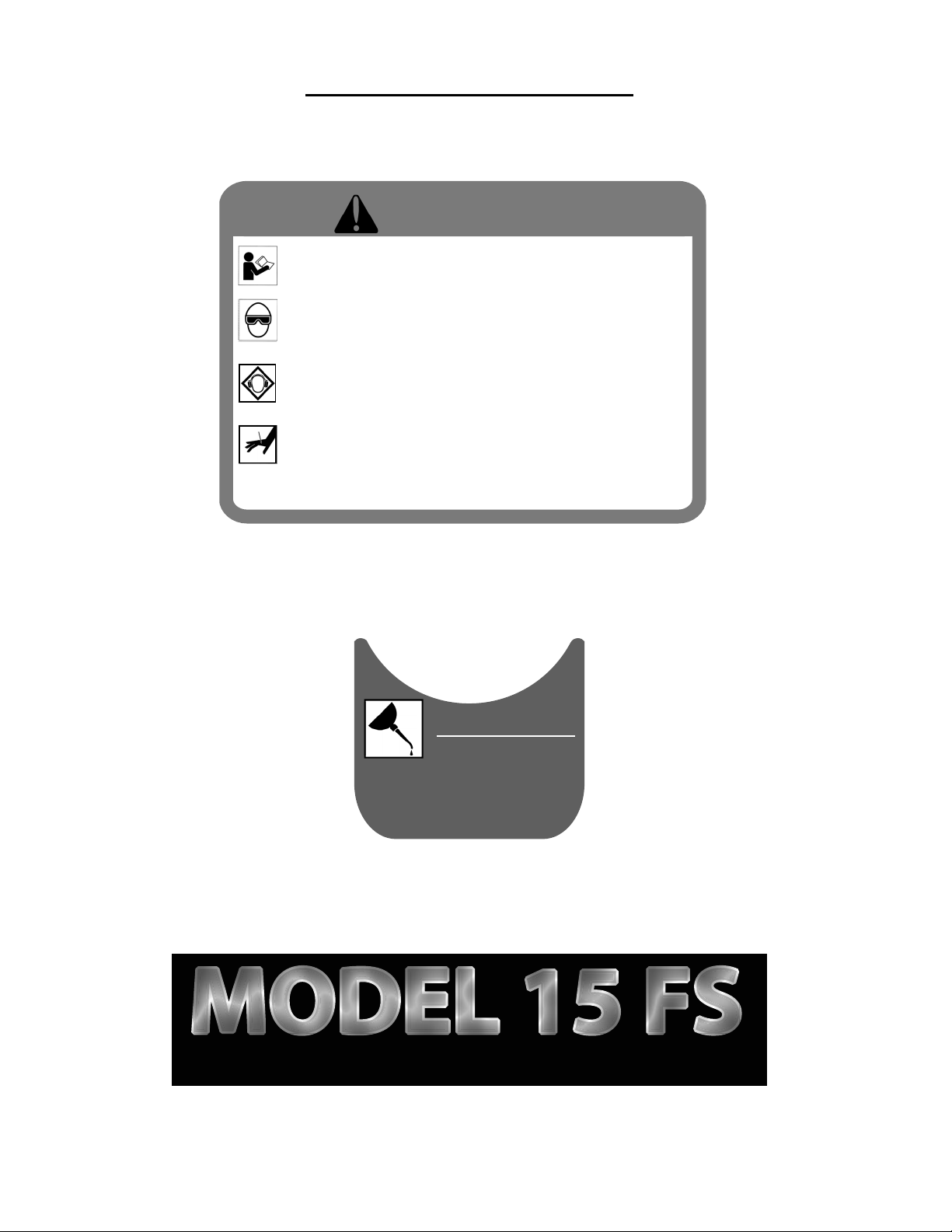
LUBRICATION:
You must lubricate the Stapler manually. The
frequency of lubrication is dependent upon
the duty cycle of the Stapler. Continuous duty
requires more frequent oiling than intermittent
duty.
At least every eight (8) hours place two to four
drops of Air Tool Oil into the disconnected air
line male connector attached to the Stapler.
WARNING: Do not over lubricate the Stapler,
excess oil mist or drops will be vented with
spent air when over lubricated. Excess oil could
stain the wood flooring, walls or furnishings.
Dry fire the Stapler, without staples, to purge
excess oil, before you begin to staple down
flooring. Before storing the Stapler, lubricate
and cycle the Stapler in insure internal parts are
oil protected from corrosion.
WARNING: Detergent oil is not recommended
and may damage the seals.
TO LOAD MODEL 15FS:
Pull back the spring loaded pusher lever until it
locks.
Place two sticks (90) PowerStaples into the
Staple Channel Feed slot.
Pull up on the pusher lever to unlock & slowly.
Release it behind the staples.
TO UNLOAD MODEL 15FS:
To remove staples from the channel, pull back
on the staple pusher until it locks. Tilt the
stapler back, the staples will slide back & can
be removed.
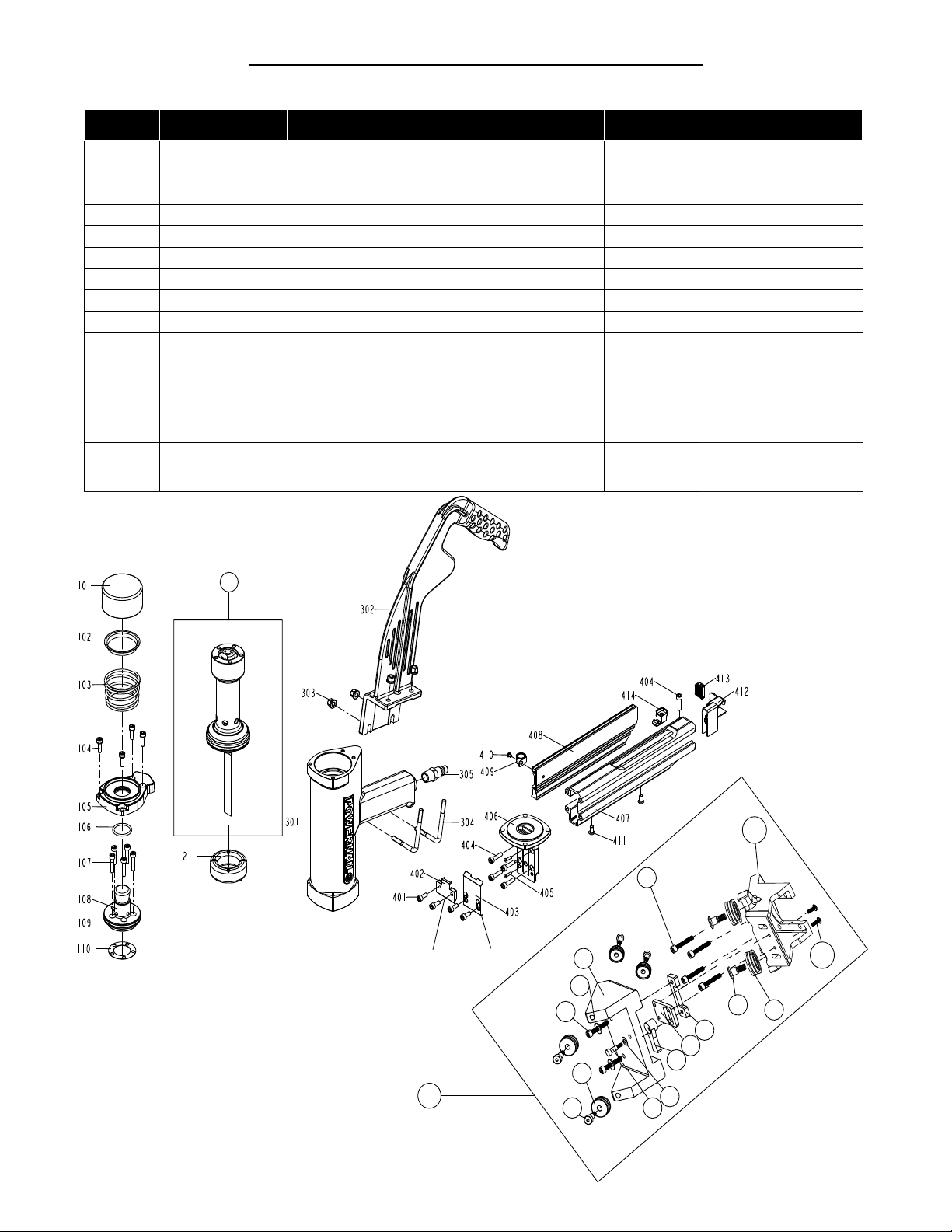
PARTS & SERVICE:
When ordering parts include the part number,
part description, PowerStapler model and serial
number.
Be sure to state the quantity of the part(s)
required. Contact your Powerstaple Dealer for
the necessary parts.
WARNING: Never work on the Stapler if the air
line is attached. Always disconnect the air line
from the Stapler first.
4
Rack the flooring into place with the rubber
end of the mallet supplied with the Stapler
Place the Stapler Roller Foot on the tongue-
edge of the flooring strip to be stapleed. Be
sure the Roller Foot is pressed tightly against
the edge of the flooring strip above the
tongue.
(Please see page 8 for detailed FLEX
Power Roller operation and adjustment)
Be sure flooring strips are racked tightly.
Strike the stapler rubber cap with the rubber
capped end of the mallet to discharge the
Stapler.
WARNING: Never hit the Stapler with
excessive force or with the metal end of the
mallet, this will damage the Stapler.
DO NOT USE THE METAL END OF THE
MALLET TO ACTIVATE THE STAPLER, use
the rubber capped end only.
Before each use, check all screws to be sure
they are tight. Shock and vibration can loosen
screws. Do not over tighten any screw.
AIR SUPPLY:
The air must be clean and dry. Dirty and/or
wet air will damage the Stapler.
Drywall Dust:
• Using Pneumatic PowerStaplers in
drywall dust conditions will dramatically
decrease the life of the Stapler.
• Drywall dust is abrasive, when cycled
through the Stapler it will cause excessive
wear.
The air source must continuously deliver 80
to 110 psi at 3-1/2 cubic feet of air per minute
to operate the Stapler. For operation, connect
a 1/4” minimum internal diameter and clean
air hose to the Stapler. Be sure the air
regulator is set at 90 psi. If the staple is not
countersunk below the surface of the wood,
turn up the air pressure, but not over 110 psi.
Check for air supply leaks that waste air and
starve the Stapler of air thereby reducing
its performance. There should be no orifice
smaller than 1/4” in the air path between the
Regulator and the Stapler.
OPERATING INSTRUCTIONS