Powernail FLEX Conversion Kit User manual

Read this manual before you use the Powernail FLEX. Follow all safety warnings and instructions. If you are
uncertain about the operation of the Powernail FLEX foot, call us directly at 1-800-323-1653 for assistance
or contact the closest Powernail Dealer for help. Please retain this information for future reference.
WARNING
REV 12.7.17
Operation and Maintenance Manual
Powernail FLEX Conversion Kit
POWERNAIL
®
CO.
1300 Rose Road, Lake Zurich, IL 60047
Phone: 1-800-323-1653
Website: www.powernail.com
A truly FLEXIBLE nailer, the FLEX is built to install 3/8” to 3/4”
Tongue & Groove flooring without the use of pads or shims.
For the Model 50P 18-Gauge Nailer

POWERNAIL FLEX
2
Powernailers® are constructed in the USA and are made
of the best materials available.
Adding to the flexibility of the Powernail
FLEX, the new Power Roller speeds up the
installation and requires less effort on the
part of the installer.
The FLEX uses an adjustable foot and you
can fine-tune the nailer height according to
different wood profiles. No need for extra
shims and pads!
The Flex with Power Roller is recommended
for use on 3/8", 1/2" and 5/8" Tongue and
OPERATION
Read these instructions carefully before you use the Nailer.
Groove flooring as well as some 3/4" exotics, bamboo,
and other solid wood flooring.
The Powernail Flex uses an 18 gage Powercleat
that is less likely to split the tongue on denser, more
brittle woods and provides an excellent bond to the
underlayment. The Powernail FLEX is designed to use
cleat lengths of 1", 1-1/4", 1-1/2", and 1-3/4".
To use the Powernail Flex with Power Roller,
adjust the nailer FLEX foot to a sample of your
flooring.
Then, simply place the nailer on the floor, pull
nailer back so locating ears catch the edge
of the floor above the tongue, pull the safety
trigger and tap the plunger with the rubber
capped mallet end to let the Nailer drive and
set the nail at the correct 45 degree angle.
Nailing with the Power Roller is faster and easier. The
nailer is designed to nail from left-to-right and aides
the installer by guiding the nailer into the flooring as
the nailer is rolling along.
Consult the flooring manufacturers recommended
nailing schedule and ensure you are nailing over a
proper subfloor.
See page 3 for instructions on correct FLEX foot
adjustment.

3
FLEX Foot Adjustment:
Wood varies from one manufacturer to the
next. The different wood profiles may be due
to height and length of the flooring tongue and
whether or not there is a nail pocket.
First, loosen the two hex bolts under the FLEX
foot with the Allen Wrench supplied with the
nailer. (Figure 1.)
Next, set the nailer on a sample of your flooring
(see Figure 2).
Use the adjustment lever at the back of the
nailer foot to raise or lower the nailer to the
wood.
Match the Adapter Foot triangles so that it is
pointing into the 90° angle created
by the tongue and the top of the wood (see
Figure 3).
For wood with a nail pocket, line up the triangles
so at the top of the nail pocket.
When the adjustment lever is in the correct
position for your wood sample, tighten the two
hex bolts to lock the FLEX foot into place.
Always check your adjustment with a sample to
ensure the nail is driving into the nail pocket
Figure 2.
Hex Allen Wrench
FLEX Adjustment Lever
1. Loosen 2 hex screws.
2. Raise or lower the FLEX to your wood sample.
3. Match the triangles to the nail pocket.
4. Tighten 2 hex screws.
5. Test wood sample with new adjustment.
Figure 1.
Figure 3.
Set the nailer on a sample of your flooring. Raise the nailer foot above the tongue
to line up the nail pocket.
ADAPTER FOOT
TRIANGLE
GAP

Figure 1.
1.
2.
3.
4.
INSTALLING THE FLEX ADJUSTABLE FOOT
Nailer Disassembly:
Remove any remaining
Powercleats®nails from the nail
channel.
Mount the nailer upside-down in a
padded vise.
Using a 3/16” hex Allen wrench,
loosen the (4) hex screws (with
lock washers) from the base of the
existing nailer foot (see figure 1).
Lift the whole foot and channel
assembly off of the nailer.
Remove the (4) 1-1/4” hex screws
from the foot and save for
re-installation.
Figure 2.
Nailer Reassembly:
Using pliers, pull the drive blade
assembly to the top of the nailer.
Install the nail channel into position
over the drive blade. Line up the
drive blade with the opening in the
nail channel (see figure 2).
Separate the nail channel from the old foot.

Figure 4.
1.
2.
3. 4.
INSTALLATION (continued)
Figure 3.
Slide the FLEX foot sideways
onto the nailer and nail channel
(see figure 3).
Line up the 4 screw holes for
each component; the foot, the
nail channel, and the nailer body.
Replace and tighten the (4) hex
screws (with lock washers) using
the 3/16” hex Allen wrench (see
figure 4).
Nailer is ready for functional
testing.

ITEM # PART NO. DESCRIPTION QTY REQ’D Key/Ref Assy/Kit
25 09-200-3057 #10-32 X 1/2 FHCS Slotted (Pad) 4 S/K A-18
48 09-445-29747 1/4-20 x 1-1/4 SHCS w/patch (Foot) 4 S/K A-18
54 09-445-29758 1/4 Split Ring Lock Washer (Foot) 4 S/K A-18
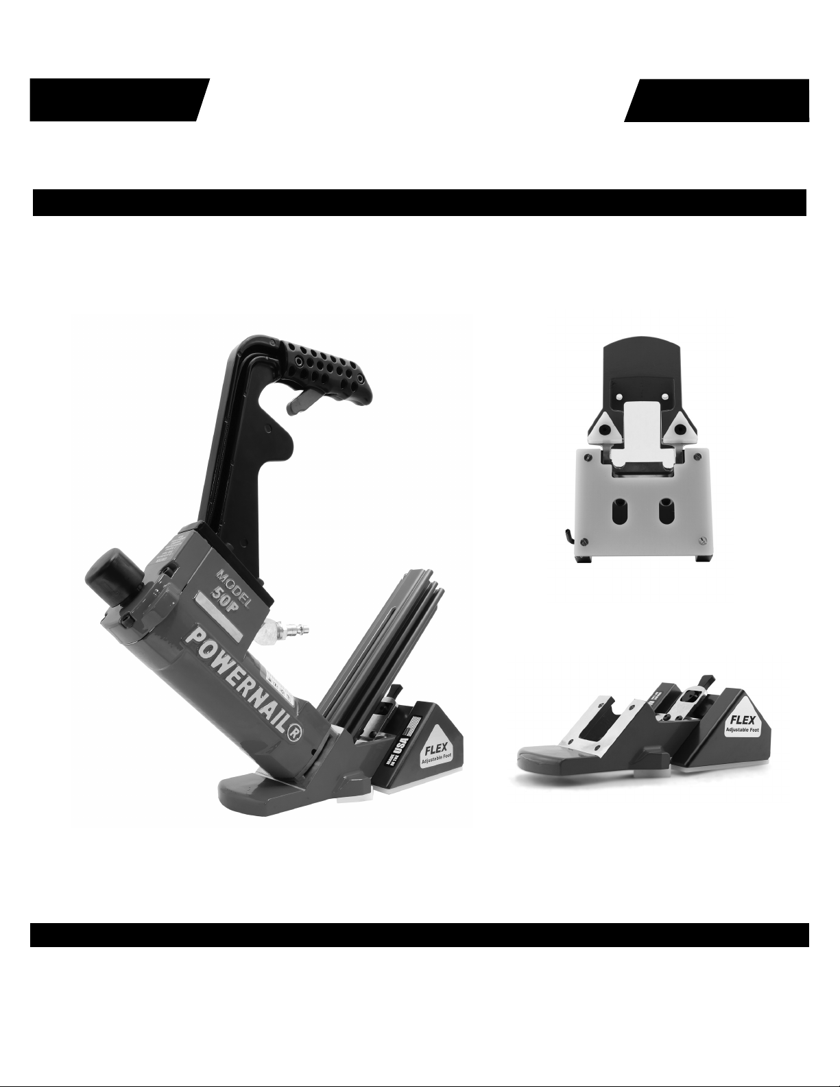
70 09-50P-3070 FLEX Foot 1 S/K A-18
71 09-50P-3071 FLEX Foot Bracket 1 S/K A-18
72 09-50P-3072 FLEX Foot Cam 1 S/K A-18
73 09-50P-3073 FLEX Foot Cam Plate 1 S/K A-18
74 09-50P-3074 FLEX Foot Pad 1 S/K A-18
75 09-50P-3075 SHCS 1/4-28 x 1.25" 2 S/K A-18
76 09-50P-3076 Washer .281 IDx.62 ODx.051" T 2 S/K A-18
77 09-50P-3077 BHCS #10-32 x .50" 2 S/K A-18
78 09-50P-3078 1/4 SH DIA x .50" SH. Bolt 1 S/K A-18
79 09-50P-3079 Belleville Disc Spring 1 S/K A-18
90 09-50P-3100 FLEX Adapter Foot (Tri-Glide) 1 S/K A-17, A-18
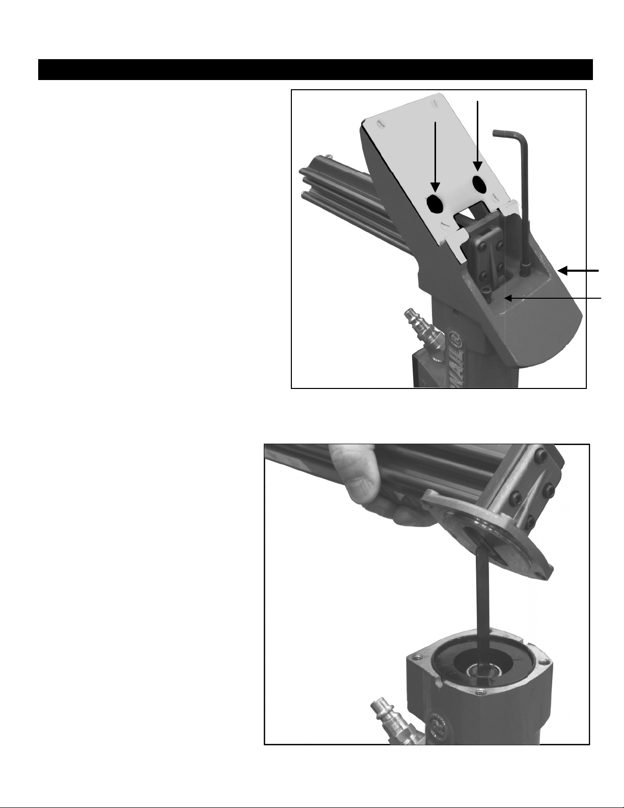
94 09-445-29801 FLEX 3/16" Allen Wrench 1 S/K A-18
105 09-50P3101A Plastic Triangle SET OF 2 (Plastic) 1 K A-17, A-18, A-19
106 09-50P3102 1/4"-20 x 3/4"L FHCS 2 S/K S, A-17, A-18
107 09-44529802 Hex Wrench 5/32" 1 S/K S, A-17, A-18
FLEX TRI-GLIDE PARTS LIST
KEY: S=Sold Separately, A= Sold as part of assembly, F=Factory replacement only, K=Sold as part of a Kit
ITEM PART NO. DESCRIPTION QTY
A-1 09-200-3058A Seal Kit (1 Each Of All Seals) 1
A-2 09-445-29759A Long Handle Assembly 1
A-3 09-445-29760A Short Handle Assembly 1
A-4 09-50P-3065A Nail Channel Assembly (Standard) 1
A-5 09-445-29824A Extra Long Handle Assembly 1
A-6 09-50P-3064A Driving Blade Assembly w/Rubber Seat 1
A-7 09-AW-445 Allen Wrench Set (3/16 & 5/32) 1
A-8 09-445-29757A 6 oz. Industrial Light Air Tool Oil 1
A-12 09-445-29768 Box Wrench (2) 2
TU 09-50P-TUKIT-R2 Tune-up Kit for all (R2) 50P, 50P FLEX, & 50P Power Rollers 1
A-14 09-50PFOOTKIT Steel foot assembly - includes R2 Foot, Gate, Gate Plate, screws 1
A-15 09-50P3050A Nail Pusher Assembly (Top Load) 1
A-16 09-50P3056A Nail Channel Assembly (Top Load) 1
A-17 09-50P3100A FLEX Tri-Glide Adapter Foot Assembly 1
A-18 06-99600 FLEX Tri-Glide Conversion Kit 1
A-19 09-50P3101A FLEX Tri-Glide Plastic Triangles - SET OF 2 (Adapter Foot) 1
06-99601 Power Roller Conversion Kit 1
09-50P3107 Tri-Glide Triangle (Aluminium) 1
Powernail FLEX Assemblies, Kits and Accessories

For this and other Powernailer schematics, please visit the
Powernail Parts Store at http://www.powernail.com
Powernail FLEX Schematic
FLEX Tri-Glide Conversion Parts.
76 78
79
72
73
71
77
25 74
75
70
48 54
90
63
106
105
66
65
64
16R2 15R2
8R2
100
39
TL
22
TL
104
101 103
102
TL
23
TL

• Dealer Locator
• Rental Locator
• Parts Store
• Product Information
The PowerPalm™
"The PowerPalm is the industries best solution to
blind nailing close to the wall. Saves both, time
and money!"
Pressure activated...simply press down, and let
the tool do the work. The Power Palm will allow
blind nailing closer to the wall and reduce the
amount of face nailing. "Blind nail, top nail...
tight spots and corners, the PowerPalm gets
them all!" Featuring 360 degree swivel tip for
fitting awkward or tight spaces. Magnetic cleat
holder keeps nail in position. Uses both 16 gage
and 18 gage Powercleats–Use the same fastener
throughout your install!
Part number: 02-PALM001
Powerjack® Model 500
Truly a Tinker's TOOL, the POWERJACK
Model 500 is designed to push or pull flooring
strips into place and hold them tightly. The
PowerJack Model 500 self adjusts from 5/16” to
3/4" thickness flooring. It can be used to either
push or pull wood flooring strips into place
and ratchets tightly for hands free operation.
The base of the PowerJack 500 has mounting
holes for mid-floor use. Simply screw nail the
PowerJack 500 to your sub floor -in front of
your flooring strips -and ratchet the flooring
strips tight. Also great for under cabinet and
kick plate installation.
Part number: 06-99650
Powerjack
Model 500
• Repair Tech Videos
• Cool Tools Cleat Calculator
• Cleat Depth Chart
• Training Schools
Closest you
can get to
the wall!
Pneumatic PowerPalm™
Visit www.Powernail.com
Featured Accessory Products
This manual suits for next models
1
Table of contents
Other Powernail Tools manuals

Powernail
Powernail 50P FLEX Installation guide

Powernail
Powernail PowerStapler 1845F User manual

Powernail
Powernail 15FS User manual

Powernail
Powernail Powerjack 500 User manual

Powernail
Powernail 445FS User manual

Powernail
Powernail 445FS User manual

Powernail
Powernail 50M FLEX MANUAL POWERNAILER User manual
Popular Tools manuals by other brands

SCA
SCA 2500KG Hydraulic Owner's instruction manual

Universal Tool
Universal Tool UT8646-1 operating instructions

Sofamel
Sofamel OPL Product Technical Specification

Nakanishi
Nakanishi RA-151E Operation manual

Josef Kihlberg
Josef Kihlberg JK20A680 operating instructions

VONROC
VONROC TT501XX Original instructions