POWERTECH PLUS MB-3613 User manual

12V / 24V, 7.2Amp / 3.6Amp 9 Stages Charging Smart Battery Charger
MB3613 User Manual
Thank you for purchasing this charger, please read this manual carefully before
use to ensure your safety and optimal use of your product.
We recommend to keeping this manual for future reference.

1
Suitable for Normal Lead Acid, Sealed, Gel or Lipo4 Batteries between 5-150Ah
for 12V batteries and 5-120Ah for 24V batteries.
IMPORTANT SAFETY INSTRUCTIONS
Gases
the battery, and the area should be kept well ventilated.
Because of this risk of explosive gas only connect and disconnect the battery leads
when the mains supply is disconnected.
Type of batteries
This charger is only suitable for normal lead acid, sealed, gel or Lipo4 batteries and
should not be used to recharge NICAD or any other type of battery.
Points of note
•When not in use, store the charger in a dry area to avoid moisture damaging the
internal parts.
Repair
•
by the user will entail the loss of your guarantee.
•The mains supply cord of this appliance can not be replaced; if the cord is dama-
ged, the appliance should be discarded.
Danger!
•Avoid getting electrolyte on your skin or clothes. It is acidic and can cause burns.
If this occurs you should rinse the affected area with water immediately.
•If it gets into your eyes - wash thoroughly and seek medical attention immediately.
•
battery into a warm area to allow battery to thaw before you begin charging. Never
let a battery on top of charger or vice versa.
•Do not touch the battery clamps together when the charger is on.
•Never operate charger if it has received a hard blow, been dropped, or otherwise
•Be sure to position the charger power cord to prevent it from being stepped on,
tripped over, or damaged.
•Never pull out the plug by the cord when unplugging the charger. Pulling on the
cord may cause damage to the cord or the plug.
Precautions When Working with Batteries
•If battery acid contacts skin or clothing, wash immediately with soap and water. If
-
tes and get medical attention immediately.
•

2
•Do not drop a metal tool on the battery. The resulting spark or short-circuit on the
battery of other electrical part may cause an explosion.
•Remove personal metal items such as rings, bracelets, necklaces, and watches
when working with a lead-acid battery.
•A lead-acid battery can produces a short-circuit current high enough to weld a
ring or the like to metal, causing severe burns.
FEATURES
Automatic and Intelligent 9-Stage Charging Curve
The MB3613 is controlled by a microprocessor with 9-stage charging characteristic
for charging batteries automobiles, motorcycles, snow mobiles, tractors, personal
watercraft, boats etc.
A microprocessor senses the condition of the battery to provide the right current and
voltage to the battery (charging characteristic). This will give the best effect on char-
ging and give the longest life to battery.
Charging characteristic:
FIG.1
24V Slow
24V GEL
Fast
24V AGM
Fast
4~28.0V ok
V03≥Er2
4~28.0V ok
V03≥Er2
4~28.0V ok
V03≥Er2
Test
2A until voltage
drops less then 4V
2A until voltage
drops less then 4V
2A until voltage
drops less then 4V
Max 4h
1A until
20V
1A until
20V
1A until
20V
5~16V 2’
16~20V 9h
Increasing voltage
until
28
V 2A
Increasing voltage
until
28
V 3.6A
Increasing voltage
until
28
V 3.6A
Current reduction
28.8V
Current reduction
28.8V
Current reduction
28.8V
/
/
/
Max 36h Max 2h
Check if voltage
dropslessthen 4V
Check if voltage
dropslessthen 4V
Check if voltage
dropslessthen 4V
1.5’’
26.20 - 28.4 4h
26.20 - 28.4 4h
26.20 - 28.4 4h
26.0 - 28.8
26.0 - 28.8
26.0 - 28.8
4h charge cycle
restarts if voltage
drops
Charge cycle
restarts if voltage
drops
12V Slow
12V GEL
Fast
12V AGM
Fast
12V
LIPO4
4~14.0V ok
V03≥Er2
4~14.0V ok
V03≥Er2
4~14.0V ok
V03≥Er2
4~14.0V ok
V03≥Er2
Test
2A until voltage
drops less then 2V
2A until voltage
drops less then 2V
2A until voltage
drops less then 2V
2A until voltage
drops less then 2V
Max 4h
1A until
10V
1A until
10V
1A until
10V
1A until
10V
5~8V 2’
8~10V 9h
Increasing voltage
until 14V 2A
Increasing voltage
until 14V 7.2A
Increasing voltage
until 14V 7.2A
Increasing voltage
until 14V 7.2A
Current reduction
14.4V
Current reduction
14.4V
Current reduction
14.7V
Current reduction
14.7V
/
/
/
/
Max 36h Max 2h
Check if voltage
dropslessthen 2V
Check if voltage
dropslessthen 2V
Check if voltage
dropslessthen 2V
Check if voltage
dropslessthen 2V
1.5’’
13.10 - 14.2 4h
13.10 - 14.2 4h
13.10 - 14.2 4h
13.10 - 14.2 4h
26.0 - 28.8
26.0 - 28.8
26.0 - 28.8
26.0 - 28.8
4h charge cycle
restarts if voltage
drops
Charge cycle
restarts if voltage
drops

3
Battery Test and Precharge (Stage 1):
Check the battery voltage to make sure battery connections are good and the battery
is in a stable condition before beginning the charge process
Desulphation (Stage2):
Detects sulfated batteries. Pulsing current and voltage, removes sulfate from the
lead plates of the battery restoring the battery capacity
Soft Start (Stage 3):
Initial battery test to determine battery condition. If the battery is severely dischar-
ged, charger will begin the Soft Start stage. Charging starts with reduced current
until battery voltage reaches a normal condition for charge.
Bulk (Stage 4):
Major charging stage where the battery receives the majority of its charge.
During this stage the battery brought to 75 - 80% of its charge. The charger delivers
maximum current until the terminal voltage has risen to the full charge level for Nor-
mal battery.
Absorption (Stage 5):
Completes the charge up to virtually 100% at a constant voltage. The current tapers
off after the current reached the minimum level.
Recondition (Stage 6):
Select “Recondition” mode, charged by higher voltage to recondition the sulfate of
the battery to save battery life.
Analysis (Stage 7):
Tests if the battery can hold charge. Batteries that can not hold charge may need to
be replaced.
Float (Stage 8):
Low constant voltage, minimal charge current, battery is fully charged
Pulse (Stage 9):
Maintaining the battery at 95-100% capacity. The charger monitors the battery volta-
ge and gives a pulse when necessary to keep the battery fully charged
Power Supply:
MB3613 has a power supply mode setting which has a constant voltage of 13.8V
and current up to 5A, keep to provide power to computer system of modern car
when replacing battery (Please don’t reverse battery connection to avoid the
damage on the charger).
Temperature Compensation
A sensor will automatically adjust the charging voltage if the temperature deviates

4
from –20°C to +45°C. A high temperature environment will lower the voltage and fre-
ezing condition is handled by higher voltage. A low temperature heightens the output
voltage, and hot condition is handled by lower voltage.
Voltage compensation
Because of some voltage drop in the cables, the actual voltage at the clamps of the
battery can be lower than the charger output voltage. A special circuitry inside the
unit will monitor the true input voltage to the battery and adjust the output voltage of
Reverse-polarity protection
This unit offers reverse-polarity protection under charging modes, the RED LED will
illuminate and the charging process will not start. If this happens, unplug immediately
from mains, connect the red clamp to positive (+) battery post, and black clamp to
negative (-) post, then plug into the mains power and the charging process will start.
Short-circuit protection
Should you accidentally touch the clamps together whilst the mains power is on, the
unit will not perform charging. Unplug from mains, disconnect and start the process
again being careful not to touch the clamps together.
Charge Memory
If power off on charging, MB3613 can automatically restart charging base on pre
-vious on previous power down status for battery and charging current.
ATTENTION: Once the clamp of charger is disconnected from the battery, this me-
mory is erased and the charging mode will need to be reselected.
Other features
Anti Spark Protection
Battery and Charger Overheating Protection
It will give a warning buzz while error occurs
Waterproof Plastic Housing. Ingress Protection Rating IP65

5
OPERATION
Charger LED display
Power LED -
Green color LED to indi-
cate Power is connect to
charger
STATUS LED -
Green color LED to indica-
te that the battery is char-
ging. Red color LED to in-
dicate a charging failure,
battery problem or reverse
polarity.
FIG.2
Charger LCD display
The unit is built-in with LCD display for showing charger status:BUTTON AND MODE
FIG.3
MODE BUTTON:
The Mode button on unit is used to select the 9 different battery charger mode
as below.
1. “12V/STD/SLOW” Mode
Slow charge (Max. 2A Charging Current) with Standard or
GEL lead acid battery
2. “12V/STD/FAST” Mode
Fast charge (Max. 7.2A Charging Current) with Standard or
GEL lead acid battery.
3. “12V/AGM/DEEP/FAST” Mode
Fast charge (Max. 7.2A Charging Current) with AGM type
lead acid battery.
4. “12V/LI/FAST” Mode
Fast charge (Max. 7.2A Charging Current) with Lipo4 battery.
Reverse
Connection
Fail in
Charging
12/24V
Supply Mode
Recondition
Mode Charging Stage
Battery
Level
Slow Charge
Mode
Lipo4
Battery
GEL / Stan-
dard Battery
Battery
Voltage
Read Out
Fast Charge
Mode
AGM
Battery

6
5. “RECONDITION” Mode
A special mode to recondition your battery after the battery
has not been used for long time or after long deep discharge
that degrade the battery performance.
The Recondition mode may decrease the battery life hence consult your battery
vendor for advise if necessary.
6. “24V/STD/SLOW” Mode
Slow charge (Max. 2A Charging Current) with Standard or
GEL lead acid battery
7. “24V/STD/FAST” Mode
Fast charge (Max. 3.6A Charging Current) with Standard or
GEL lead acid battery.
8. “24V/AGM/DEEP/FAST” Mode
Fast charge (Max. 3.6A Charging Current) with AGM type
lead acid battery.
9. “POWER SUPPLY” Mode
voltage, with max. of 5A current.
START CHARGING YOUR BATTERY
PLEASE READ CAREFULLY BEFORE USING
Suitable for 12V and 24V Normal Lead Acid, Sealed, Lipo4, Leisure or Gel Bat-
teries between 5-150Ah for 12V batteries and 5-120Ah for 24V batteries.
1. PREPARING THE BATTERY
•Firstly remove the caps from each cell and check that the level of the liquid is
distilled water.
Note: Under no circumstances should tap water be used.
•The cell caps should not be replaced until charging is complete. This allows any
gases formed during charging to escape. It is inevitable that some minor escape of
acid will occur during charging.
For permanently sealed battery, it is not necessary to carry out the above checks.
2. CONNECTION
•Connect the positive charging lead (red) to the positive terminal post of the bat-
tery (marked P or +). Connect the negative charging lead (black) to the negative
terminal post of the battery (marked N or -).
Once you connected the MB3613 battery charger to AC power, it will sound
a tone for 0.5 seconds and all of the LEDs on the touch panel will be on for a
short time.
Warning! Always disconnect the AC plug from the AC mains socket before
connecting or disconnecting the appliance to or from the battery.

7
3. CHARGING
•Connected to power supply and the battery, the charger will automatically enter into
charging status, it is working on slow charging stage for 12V batteries by default. The
slow charge icon will illuminate, and the charger is automatically detecting the battery.
This is the standard charging mode.
•
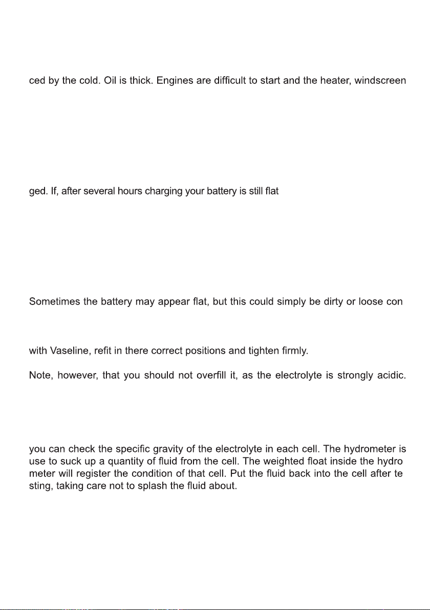
different charging mode:
1. Hold the Mode key to switch to 24V and back.
2. Pressing the mode key to select one of the nine charge modes.
•After 5’’ the charge starts according tothe setting.
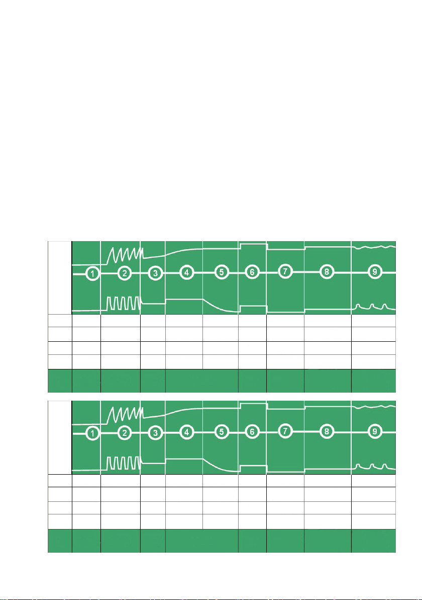
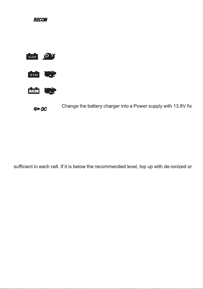
4. WHEN CHARGING IS COMPLETE
When the Stage 8 icon and Full illuminates, the battery is completely
charged. The battery charger now switches to the Float mode and doesn’t require
your attention until the next time it is used, it will automatically maintain your battery.
If LCD stage 9 icon illuminates, it indicates that the charger has automatically
maintained your battery.
Switch off the mains supply, unplug the charger, and disconnect the leads from the
battery posts. NOT to be done for permanently sealed battery: Inspect the liquid
extreme care as it may be acidic/corrosive).
Where appropriate, if the battery has been removed for charging, replace it and
reconnect the cables.
5. BATTERY FAULT
If fail red LED indicator lights or blinks and LCD Fail icons illuminate,
the following occurs:
Er1 - Fail Red LED blinks
Improper connection of Charger and battery polarity
Er2 - Wrong battery
Battery voltage 12V mode ≥15V, 24V mode ≥30V
Er3 - Battery voltage doesn’t reach a normal condition for charge.
12V (4V- 8V 2Min ) , (8V-10V 9Hr)
24V (4V-16V 2Min ) , (16V-20V 9Hr)
Er4 - Battery that can not hold charge
Er5 - Charging stopped under “Desulphation” or “ Absorption” mode, then press “MODE”
button could resume to charging, if still have the same problem, maybe caused by:
•1. Battery is over-sulfated
•2. Battery can’t be charged
•3. Battery can’t hold the charge
Under these conditions, the battery charger will stop charging.
Flashing red LED and a buzzer mean wrong battery voltage selection.

8
MAINTENANCE AND CARE
It is essential to keep your battery regularly charged throughout the year, especially
during the winter months. In the winter the effectiveness of your car battery is redu-
wipers and lights are all draining power. It is at this time that batteries have to be at
peak power. If your battery is not regularly maintained and kept fully charged, it can
cause problems and a possible breakdown.
Listed are some helpful hints on how to keep your battery healthy in conjunction with
your Battery Charger.
Faulty Cells
Batteries are usually made with six cells. One of these cells can deteriorate or get dama-
, you should test the battery.
ONLY for NOT sealed batteries:
Take hydrometer readings from each cell in the battery. If one reading is lower than
the others, this could indicate a faulty cell. If necessary, get an Auto-Electrician to
check your battery. One faulty cell is enough to ruin your battery.
It is pointless to continue using it and you would be better getting a new one.
Care
-
nections on your battery terminals. It is important to maintain the leads on a regular
basis. Do this by removing the leads from the battery, clean the inside of each con-
nector and terminal posts on the battery, smear the terminal posts and connectors
It is essential to keep the electrolyte level above the plates.
When topping up do not use tap water. Always use distilled or de-ionized water. It
is important to keep the acid level up. If necessary have it checked by your garage.
Checking the condition of your battery (ONLY for NOT sealed batteries)
Using a hydrometer, which can be purchased, from most motor accessory stores,
-
-
Other manuals for MB-3613
1
Table of contents
Other POWERTECH PLUS Batteries Charger manuals
Popular Batteries Charger manuals by other brands

e-bike vision
e-bike vision 24882-1 operating instructions

Shimano
Shimano Ultegra SM-BCR1 manual

Knightsbridge
Knightsbridge LEDADP36 Series Installation & maintenance manual

Schumacher
Schumacher SPI6 owner's manual

ISDT
ISDT D2 Mark II user guide

ProMariner
ProMariner ProSport6 PFC Owner's manual and installation guide