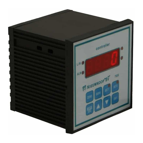
PPI FLOREX User manual

FLOREX
User Manual
Flow Rate Indicator Cum
Totaliser
TOTAL FLOW
18925.682

CONTENTS
User Manual
FLOREX
1. PANEL MOUNTING AND ELECTRICAL CONNECTIONS 1
2. FRONT PANEL : LAYOUT AND OPERATION 3
3. PAGES AND PARAMETERS 10
4. 14FLOW ALARM PARAMETERS
5. 16TOTAL ALARM PARAMETERS
6. 18 RETRANSMISSION PARAMETERS
7. 19INPUT CONFIGURATION PARAMETERS
8. SUPERVISORY PARAMETERS 22
9. SERIAL CONFIGURATION PARAMETERS 23
10. UTILITY PARAMETERS 24
11. USER LINEARISATION PARAMETERS 25
12. HARDWARE ASSEMBLY & CONFIGURATION 27
13. MECHANICAL INSTALLATION 33
14. ELECTRICAL CONNECTIONS 35

FRONT PANEL LAYOUT
The FLOREX front panel comprises of digital readouts, LED indicators and membrane keys as shown in Figure 1.1 below.
Figure 1.1
READOUTS
The Upper Readout is a 5 digit, 7-segment bright red LED display and usually displays the Flow Rate.
The Lower Readout is a 16 characters X 2 Rows LCD with Green Backlight and usually displays Total Flow. In View Only
Mode, the Lower Readout scrolls the operator view only parameters. In Operator Mode, the Lower Readout displays operator
and in Program Mode, the Lower Readout displays the programming parameter names and their corresponding values /
options.
The indications on the Lower Readouts, in general, depend on the mode of operation and configuration parameters. Refer
respective sections for more details.
INDICATORS
There are six front panel LED indicators viz. Three Red LED for Flow Rate Status and three Green LED for Flow Total status.
These indicators show various statuses. The Table 1.1 below lists each LED indicator (identified by the front panel legend) and
the associated status it indicates.
1
User Manual
FLOREX
Upper Readout
Lower Readout
ENTER Key
UP Key
DOWN Key
PAGE Key
Alarm-2 TotaI Indicator
Alarm-1 TotaI Indicator
Alarm-1 Rate Indicator
Alarm-2 Rate Indicator
Reset Key
Acknowledge Key
Scroll Key
Operator Key
Table 1.1
Indicator Function
• Glows while the Flow Rate is indicated by applying Square Root
Calculation.
• Remains OFF if the Flow Rate is indicated without applying Square Root
Calculation.
Indicates Alarm-1 status if Alarm-1 for Flow Rate is set to other than ‘none’
• Flashes while the Alarm-1 is active.
• Glows when the Alarm-1 is active and latched.
• Remains OFF while the Alarm-1 is inactive.
SQR
AL1
RATE
Indicates Alarm-2 status if Alarm-2 for Flow Rate is set to other than ‘none’
• Flashes while the Alarm-2 is active.
• Glows when the Alarm-2 is active and latched.
• Remains OFF while the Alarm-2 is inactive.
AL2
RATE
Section 1

Indicator Function
Indicates Alarm-1 status if Alarm-1 for Flow Total is set to other than ‘Enable’
• Flashes while the Alarm-1 is active.
• Glows when the Alarm-1 is active and latched.
• Remains OFF while the Alarm-1 is inactive.
AL1
TOTAL
Indicates Alarm-2 status if Alarm-2 for Flow Total is set to other than ‘Enable’
• Flashes while the Alarm-2 is active.
• Glows when the Alarm-2 is active and latched.
• Remains OFF while the Alarm-2 is inactive.
AL2
TOTAL
• Glows while the Flow Total value overflows the maximum Total value.
• Remains OFF while the Flow Total value is less than the set Total value.
OVF
KEYS
There are eight tactile keys provided on the front panel for configuring the FLOREX selecting View Only parameters, setting-
up the program Mode and selecting Operation Parameters.
The Table 1.2 below lists each key (identified by the front panel symbol) and the associated function.
Table 1.2
User Manual
FLOREX
2
Symbol Key Function
ACKNOWLEDGE
OPERATOR
SCROLL
RESET
UP
ENTER
DOWN
PAGE Press to enter or exit set-up mode.
Press to store the set parameter value and to scroll to the next
parameter on the PAGE.
Press to increase the parameter value. Pressing once
increases the value by one count;keeping pressed speeds up
the change.
Press to decrease the parameter value. Pressing once
decreases the value by one count; keeping pressed speeds up
the change.
Press to Reset the Flow Total value to zero.
Press to scroll through the various display fields individually on
Lower Readout in View Only Mode.
Press to access the Operator Mode.
Press to manually Acknowledge the Rate/Total Alarms if the
Alarm latch is enabled.

POWER-UP
Upon switching on the power to the instrument, all displays and indicators are lit on for approximately 3 seconds during which
time the instrument runs through a self-test sequence. This is followed by the indication of the instrument model name and
firmware version on the Lower Readout as , for approximately 1 second.
MAIN DISPLAY MODE
BASIC OPERATIONS
FLOREX
H/W: 1S/W: 1
Figure 2.1
After the Power-up display sequence, the Upper Readout starts showing the measured Flow Rate and the Lower Readout
displays the accumulated Flow Total.
This is called the MAIN Display Mode and this is the one that shall be used most often. The MAIN Display Mode is depicted in
Figure 2.1.
FIRST TIME / NEW INSTALLATION
For a first-time installation of a new instrument or if the instrument is removed from one application and installed on different
application, it is recommended to subsequently observe the following sequence of parameter settings that are required for
instrument’s intended operation. (Refer Section 3 : Pages & Parameters for details on parameter settings).
1. Set the Input Configuration Parameters.
2. Set the Supervisory Parameters.
3. Set the Flow Rate Alarm Parameters (if required).
4. Set the Flow Total Alarm Parameters (if required).
5. Set the Retransmission Parameters (if required).
6. Set the Serial Configuration Parameters (if required)
Upon completion of parameters settings, the FLOREX reverts to MAIN Display Mode. The Florex, now, can be programmed to
operate in the intended Operation Modes as described below.
OPERATION MODES
The FLOREX can be operated in the following operation modes.
Flow Rate Indication
The Florex accepts DC Linear Current / Voltage Input from the Flowmeters to measure the Flow Rate. The value of the Flow
Rate is displayed in accordance with the value for Range Low / High and the Resolution selected on Input Configuration Page.
The measured value of Flow Rate can be directly displayed or by applying Square Root Function (if the Square Root Function
is enabled on Input Configuration Page).
User Manual
FLOREX
3
Section 2

Totaliser Operation
The Totaliser mode is used primarily to monitor accumulated Flow Total. The calibrated analog signal (derived from Flow Rate
Signal Input) is used to drive the Totaliser. The FLOREX keeps adding the currently measured value of Flow Rate with the
previously measured value and displays the continuously updated accumulated Total Flow on the Lower Readout (Eight Digit,
LCD) until the another view only parameter is selected on Lower Readout by pressing SCROLL key.
The Resolution for the Flow Total value is same as that selected for Flow Rate value. The Totaliser display may be reset from
the Front Panel using RESET (RST) key.
Issuing Total Reset Command
The accumulated Flow Total can be Reset to 0 by issuing Total Reset Command. The ‘Reset Command’ can be locked under
supervisory level The ‘Reset Command’ can be locked under supervisory level and will be effective only if it is Command.
unlocked at operator level.
1. Press Total Reset (RST) key while the FLOREX is in MAIN Display Mode. The Lower Readout displays
2. Use UP/DOWN key to adjust the value of the Passcode. Notice that this Passcode value should match with the value set
for the ‘Supervisory Passcode’ on Utility Page.
3. Press ENTER key to Reset the Total value to 0.
Notice that upon resetting the Flow Total to 0, the FLOREX immediately starts accumulating the Flow Total if the Flow Rate is
other than 0. If the set Passcode value does not match with the value set for the Supervisory Passcode set on Utility Page, the
FLOREX reverts to MAIN Display Mode without resetting the accumulated Total.
If the value set for ‘Supervisory Passcode’ is set to 0, the Flow Total will immediately get Reset to 0 upon pressing ENTER key.
Batch Operation
The FLOREX can be configured to operate in Batch Control mode primarily used to control batches. The main difference
between the Batch mode and Rate/Total mode is the relay operation. To configure the FLOREX in Batch Control Mode, the
option for the parameter ‘Total Alarm Logic’ is to be set to ‘Reverse’ on Total Alarm Page.
The FLOREX is provided with Two Setpoints for Flow Total. The user can configure one setpoint as a Pre-warn value below the
final Total Flow value.
The Batch mode allows the operator to "START" the batch upon power-up the FLOREX or issuing ‘Reset Command’ via the
front panel RESET (RST) key. Once started, the output-1 and output-2 (Relay / SSR) will energize and send power to a flow
control device (i.e. solenoid valve or pump). The flow sensor will send a signal to the FLOREX and total accumulation will
begin.
When the Pre-warn value (Total Setpoint-1) is reached, Relay 1 will drop out (this is ideal for flow slow down). When the Batch
amount is reached to the Final value (Total Setpoint-2), Relay 2 will drop out and the Batch will be completed. During batch is
running, the setting of Flow Total Alarm Logic to ‘Normal’ from ‘Reverse’ is inhibited.
Alarm Operation
The FLOREX is provided with two independent alarm setpoints for Flow Rate as well as Flow Total. Depending upon the Alarm
Type selected, the Flow Rate alarm is activated/de-activated by comparing the measured Flow Rate with the value set for the
Alarm Setpoint by the set value for Alarm Hysterisis.
If the Total Alarm is enabled, the Total Alarm is activated by comparing the accumulated total with the set value for Total Alarm
Setpoint.
(For more details on Alarm Parameters, Refer the respective sections of Flow and Total Alarm Parameters.)
PASS CODE >>
0
User Manual
FLOREX
4

Alarm Acknowledgment
The FLOREX is provided with the output (Relay/SSR) facilitating “hard” alarm for Flow Rate as well as Flow Total. That is, if
any or both the alarms are activated (alarm condition is occurred), the output (Relay/SSR) associated with their respective
alarms gets energized and sounds the buzzer/hooter.
The output (Relay/SSR) remains energized until the alarm condition is automatically / manually removed, by Auto Reset or the
user manually acknowledges the alarm condition by pressing the Alarm Acknowledgment (ACK) key
Note that upon pressing this key, the Alarm output switched OFF but the Alarm LED indications will remain continue until the
Alarm condition is removed. However, if the Alarm condition is not removed, the FLOREX continues to indicate the alarm
status by flashing the alarm status LED indicators. If the Alarm condition is removed prior to acknowledging the alarm, the
FLOREX will automatically switched OFF the alarm output and alarm indication. If the Alarm condition is removed after
acknowledging the alarm, the FLOREX will activate the alarm only if new alarm condition will occur.
STORAGE OF MIN. & MAX. FLOW RATE
The FLOREX has a unique feature of view and store the Minimum and Maximum value of measured Flow Rate. This facilitates
user to view the Maximum (Overshoot) and Minimum (undershoot) of Flow Rate from its present value. These values can be
viewed by entering into Operator Page while the FLOREX is in MAIN Display Mode if this feature is enabled under supervisory
level.
Step through the following sequence to View and Reset the Minimum and Maximum value of Flow Rate, if this facility is
enabled under supervisory level.
1. Press SCROLL key from MAIN Display until the Lower Readout displays
Notice that the Right Hand side of the Lower Readout shows the stored Minimum value of Flow Rate.
2. Press SCROLL key once again. The Lower Readout now displays
Notice that the Right Hand side of the Lower Readout shows the stored Maximum value of Flow Rate.
Issuing Min. / Max. Reset Command
Further, these stored values can be Reset by issuing the ‘Reset Command’. In Reset, the stored values of Minimum and
Maximum Flow Rate get erased and overwritten with the present value of Flow Rate. The ‘Reset Command’ can be locked
under supervisory level and will be effective only if it is unlocked at operator level.
1. Press Operator (OPR) key to enter into Operator Page from MAIN Display and keep pressing ENTER key until the Lower
Readout displays Reset Min./Max. Command
2. Use UP key to set the option ‘No’ to ‘Yes’. The Lower Readout displays
3. Press ENTER key to register ‘Yes’ Command. The Lower Readout now displays
4. Use UP/DOWN key to adjust the value of the Passcode. Notice that this Passcode value should match with the value set
for the ‘Supervisory Passcode’ on Utility Page.
5. Press and release ENTER key.
The set value is registered and if matched with the ‘Supervisory Passcode’, the stored Min./Max. Value of Flow Rate will get
erased and the present value of Flow Rate is stored as both Min./Max value of Flow Rate.
Notes:
1. The storage and view of Minimum & Maximum value of Flow Rate is available as long as this feature is Enabled on Supervisory Page. If
this feature is disabled on Supervisory Page, the storage and view of Minimum & Maximum value of Flow Rate function will not be
available.
MIN. FLOW RATE
0
MAX. FLOW RATE
0
RESET MIN. MAX.>
No
RESET MIN. MAX.>
Yes
PASS CODE >>
0
User Manual
FLOREX
5

2. In case Flow Rate Error conditions like Or (Over-Range) or Ur (Under- Range) occurs, even if the MAIN display of FLOREX flashes
Error message, the FLOREX stores and views the actual counts available for Flow Rate Error condition as Minimum & Maximum value
of Flow Rate instead of viewing Flow Rate Error message. It is, therefore, recommended to Reset these stored values upon removing
the Flow Rate Error conditions to store and view the presently available values of Minimum & Maximum value of Flow Rate. Else, the
FLOREX will continue to view the actual counts stored at the instant Flow Rate Error condition occurred.
3. If the power supply to the FLOREX is switched-off or a power-failure occurs while the Storage of Minimum & Maximum value of Flow
Rate is enabled, upon resumption of power, if the power-on measured Flow Rate is found above the Maximum value or below the
Minimum value stored prior to power-failure, the FLOREX stores and views the power-on measured Flow Rate as Minimum or
Maximum value of Flow Rate, respectively. Else, the Minimum & Maximum value of Flow Rate stored prior to power-failure are remain
intact.
4. By default, the Storage on Minimum & Maximum value of Flow Rate feature is disabled on Supervisory Page. Therefore, this feature will
not be available upon carrying “Setting Default Value” procedure.
VIEW ONLY PARAMETERS
The Table 2.1 below describes the view only parameters followed by the definition of each parameter. Notice that these
parameters are for view only. That is, their values can not be altered by the user.
The View Only parameters are selected to display on Lower Readout by pressing SCROLL (SCR) key while the FLOREX is in
MAIN Display Mode. The user can revert to MAIN Display Mode from any parameter just by pressing ENTER key.
Parameter Description Settings
(Default Value)
TOTAL TIME
This parameter shows the Total Time elapsed from the Power-up
of FLOREX. The Total Time is shown in Hour : Minute : Second
Format. This parameter allows the user to view the Total Time
within which the Total Flow is accumulated. This Timer is
automatically get Reset upon resetting the accumulated Flow
Total and re-starts counting the Time period again from 0
automatically.
Time (HH:MM:SS)
00:00:00
This is parameter is available only if the ‘Storage of Minimum &
Maximum of Flow Rate’ is enabled on Supervisory Page. This
parameter views the currently stored Minimum value of Flow Rate.
MINIMUM FLOW RATE
Table 2.1
User Manual
FLOREX
6
MAX. FLOW RATE
100
MAXIMUM FLOW RATE
This is parameter is available only if the ‘Storage of Minimum &
Maximum of Flow Rate’ is enabled on Supervisory Page. This
parameter views the currently stored Maximum value of Flow
Rate.
MIN. FLOW RATE
0

Parameter Description Settings
(Default Value)
This parameter shows the number of counts for which the
accumulated Flow Total overflows from the maximum (99999999)
counts. This parameter allows the user to count that how many
times the Total Flow has overflow from the maximum counts. This
parameter will automatically get Reset to 0 upon issuing Total
Flow Reset Command.
NO. OF OVERFLOWS
NO.OF OVER FLOW
0
OPERATOR PARAMETERS
The FLOREX facilitates a separate group for Operator Parameters to provide operational ease for normal day-to-day
operations and to avoid unauthorized access to the FLOREX Program Mode.
The Operator Mode can be entered by the Front Panel key labeled OPERATOR (OPR) and the list of various operator
parameters can be set using UP/DOWN and ENTER key.
Step through the followings to adjust the Operator Parameter values.
1. While the FLOREX is in MAIN Display Mode, press and release the OPERATOR key. The Lower Readout displays the first
-parameter in the list.
2. Use UP/DOWN key to set the value for various operator related parameters and press ENTER key to register the set value
and scroll to next parameter in the list.
The Operator Parameters are listed in Table 2.2 below followed by their respective definitions.
Parameter Description Settings
(Default Value)
This command allows the user to manually acknowledge the
“hard” alarm. This command is available and applicable only if the
Alarm Latch is enabled, the alarm condition is occurred and not
yet acknowledged. Once the alarm is acknowledged, this
command will be available only if the alarm condition is occurred
for the next time. This command has two possible settings. It
serves as a Command to Acknowledge the hard (sounding of
buzzer/hooter) and the alarm status indication
ALARM ACKNOWLEDGE
No
Yes
(Default : No)
User Manual
FLOREX
7
Table 2.2
No
Yes
(Default : No)
MIN./MAX. RESET COMMAND
This parameter is available and applicable only if the ‘Storage of
Minimum & Maximum value of Flow Rate’ is enabled on
Supervisory Page. It has two possible settings.

Parameter Description Settings
(Default Value)
This parameter is available and applicable only if the ‘Reset
Command’ for ‘Storage of Minimum & Maximum value of Flow
Rate’ is set to ‘Yes’ on Operator Page. The numeric value entered
for this parameter should match with the numeric value set for the
‘Supervisory Passcode’ for ‘Reset Command’ on Utility Page to
make the ‘Reset Command’ effective. If the value entered for this
parameter does not match with the value set for ‘Supervisory
Passcode’ for ‘Reset Command’ on Utility Page, the ‘Reset
Command’ will not be effective even if it is set to ‘Yes’ and the
previously stored Minimum & Maximum value of Flow Rate will
remain intact.
PASSCODE VALUE
0 to 250
(Default : 0)
No :
If for any reason, the accumulated Flow Total is not to be Reset
yet, issue this as a Command to intact the previously accumulated
values.
Yes :
This Command Resets the previously stored accumulated Flow
Total to 0. The ‘Total Reset Command’ will be effective only if the
value entered for ‘Passcode’ matches with the ‘Supervisory Code’
for Reset Command set on Utility Page .
TOTAL RESET COMMAND
No
Yes
(Default : No)
The definition and operation of this parameter is same as that
described for the parameter ‘Passcode Value’ for ‘Min./Max.
Reset Command’, but applicable for ‘Total Reset Command’. Note
that the value set for ‘Supervisory Passcode’ is commonly
applicable for both ‘Min./Max. Reset Command’ and ‘Total Reset
Command’.
PASSCODE VALUE
0 to 250
(Default : 0)
This parameter is available only if ‘Flow Alarm-1 Type’ is selected
to other than ‘None’. If the Alarm Type is selected as ‘Process
High’, the alarm is activated whenever the measured Flow Rate is
at or above the set value. Similarly, if the Alarm Type is selected as
‘Process Low’, the alarm is activated whenever the measured
Flow Rate is at or below the set value.
FLOW ALARM-1 SETPOINT
User Manual
FLOREX
8
The definition of this parameter is same as that described for Flow
Alarm-1 Setpoint but applicable for Flow Alarm-2 Setpoint.
FLOW ALARM-2 SETPOINT
(Default :
For Process Low : 0 ,
For Process High : 1000)
0 to 30000
(Default :
For Process Low : 0 ,
For Process High : 1000)
0 to 30000

Parameter Description Settings
(Default Value)
TOTAL ALARM-1 SETPOINT
This parameter is available only if ‘Total Alarm-1’ is selected to
‘Enable’. If enabled, the alarm is activated whenever the
accumulated Flow Total is at or above the Total Alarm-1 Setpoint.
0 to 99999999
(Default : 5000000)
This parameter is available only if ‘Total Alarm-1’ is selected to
‘Enable’. If enabled, the alarm is activated whenever the
accumulated Flow Total is at or above the Total Alarm-1 Setpoint.
TOTAL ALARM-1 EXT. SETPOINT
0 to 125
(Default : 0)
TOTAL ALARM-2 SETPOINT
The definition of this parameter is same as that described for Total
Alarm-1 Setpoint but applicable for Total Alarm-2 Setpoint.
0 to 99999999
(Default : 5000000)
The definition of this parameter is same as that described for Total
Alarm-1 Setpoint but applicable for Total Alarm-2 Setpoint.
TOTAL ALARM-2 EXT. SETPOINT
0 to 125
(Default : 0)
Note:
The Flow Alarm and Total Alarm Setpoints are available for adjustment only if their adjustment is enabled under supervisory level on
Supervisory Page, else available for view only. (For more details on Alarm Parameters, Refer the respective sections of Flow and Total Alarm
Parameters.)
User Manual
FLOREX
9

ORGANIZATION
The FLOREX requires various user settings that determine how the FLOREX will function or operate. These settings are
called Parameters.
The parameters are always presented in a fixed format: The Upper Row of Lower Readout displays the parameter name
(Identification Tag) and the Lower Row displays the options / set value. The parameters appear in the same sequence as listed
in their respective sections.
For convenience and ease of memorizing, the various parameters have been arranged in different groups depending upon the
functions the parameters represent. Each group is assigned a unique Page Header for its access and the parameters within
each group are presented for settings depending upon the function(s) selected.
PROGRAM MODE
The Program Mode allows the user to view or modify the parameter values. The entry from MAIN Display Mode to Program
Mode requires appropriate setting of the Page Header. Follow the steps below to open a desired PAGE for setting the
parameter values
1. Press and release PAGE key. The Upper Row of Lower Readout shows SELECT PAGE and the Lower Row shows first
Page Header. See Figure 3.1.
2. Adjust the Lower Readout to the desired Page Header using the UP/DOWN keys. Pressing and releasing the UP or DOWN
key once, access to the next or previous Page Header.
3. Press and release ENTER key. The Upper Row of Lower Readout shows the name of the first parameter listed in the Page
and the Lower Row shows its current value / option.
PAGES AND PARAMETERS
Figure 3.1
SELECT PAGE>>
FLOW ALARAMS
Adjusting Parameter Values
Once a PAGE is accessed, step through the following sequence to adjust the values of the desired parameters:
1. Press and release the ENTER key until the name for the required parameter appears on the Lower Readout. The last
parameter in the list rolls back to the first parameter.
2. Use UP / DOWN keys to adjust the parameter value. Note that some parameters (examples; ‘Alarm Setpoint’, ‘User
Offset’, etc.) have numeric values while others (examples; ‘Alarm Logic’, ‘Time Base’, etc.) have a series of options. If
adjusting a numeric value; depressing the UP/DOWN key once, increases/decreases the parameters value by one digit.
For parameters having a series of options, depressing the UP/DOWN key once takes you to the next/previous option. In
each case, keeping the UP/DOWN key pressed speeds up the rate. If the value reaches the maximum / minimum settable
value/option, the Lower Row starts flashing and the UP (if maximum value is reached) or DOWN (if minimum value is
reached) key has no effect.
User Manual
FLOREX
10
Section 3

3. Press and release the ENTER key. The new value gets stored in the FLOREX’s non-volatile memory and the next
parameter in the list is displayed.
The Figure 3.2 illustrates the example of altering the value for the parameter ‘Flow Alarm-1 Type’.
AL1 TYPE >>
None
AL1 TYPE >>
Process Low
Al1 SETPOINT >>
0
Figure 3.2
To exit the Program Mode and return to the MAIN Display Mode, press and release PAGE key.
Notes:
1. It is a must to press the ENTER key after altering the value of a parameter else the new value will not be registered / stored. That is, a
return to the MAIN Display Mode (by depressing PAGE key) without pressing the ENTER key will not store the altered value in the
FLOREX memory and the previous set value will be retained. Also, if the power failure occurs prior to pressing ENTER key, upon
resumption of power, the FLOREX reverts to MAIN Display Mode without storing the altered value and retaining the previous set value.
2. If the FLOREX is left in Program Mode for more than 30 seconds without any key operation, the FLOREX automatically exits the
Program Mode and returns to the MAIN Display Mode.
CONDITIONAL PARAMETERS
As discussed above the various parameters (user set values) are grouped and listed in separate PAGES. For convenience,
each PAGE contains a list of parameters that relate to some specific functions or operations.
Note, however, that not all parameters are always presented to the user. Some parameters are presented only if the
corresponding function is selected. Such parameters are called the conditional parameters, as their availability is dependent
on the options selected for some other parameters (in the same or other PAGE). For example, consider the ‘Alarm
Parameters’ contained in Flow and Total Alarm PAGE. These parameters are presented only if the respective ‘Alarm Type’ is
selected to other than ‘None’.
Suppressing the conditional parameters (if the conditions are not met) avoids ambiguity and makes the parameter list more
comprehensive. Refer the definitions below each parameter table (listed in the following 6 sections) for the conditional
parameters. Also note that the parameters appear in the same sequence as shown in the table for each PAGE
PARAMETER LOCKING
Though access to any PAGE is always permitted, the adjustment of the parameter values, however, can be Locked at the
supervisory level. If the Lock is enabled, the parameter values in each PAGE can only be viewed but can not be adjusted. That
is, the UP/DOWN key functions are inhibited. This feature facilitates the supervisory level to protect the parameter values from
unauthorized tampering or accidental alterations by the operator.
The FLOREX is shipped from the factory in Unlocked (Lock disabled) condition. The user can enable the Lock once the initial
configuration and installation is done.
For enabling / disabling the Lock, step through the following sequence:
Locking
1. Press and release PAGE key while the FLOREX is in the MAIN Display Mode. The Lower Readout displays
2. Adjust the Lower Row to select Utilities Page using UP key and press ENTER key. The Lower Readout displays
3. Use UP key to set the value of the Pass Code to 22 and press ENTER key. The Lower Readout displays
4. Press ENTER key. The Lower Readout displays Use UP key to set the option to Yes and press ENTER key.
The FLOREX returns to the MAIN Display Mode with the Lock enabled.
User Manual
FLOREX
11
SELECT PAGE >>
FLOW ALARMS
ENTER PASSCODE >>
0
SELECT
LOCK/UNLOCK
LOCK >>
NO

Unlocking
1. Press and release PAGE key while the FLOREX is in the MAIN Display Mode. The Lower Readout displays
2. Adjust the Lower Row to select Utilities Page using UP key and press ENTER key. The Lower Readout displays
3. Use UP key to set the value of the Pass Code to 22 and press ENTER key. The Lower Readout displays
4. Press ENTER key. The Lower Readout displays Use UP key to set the option to Yes and press ENTER key.
5. Repeat steps 1 through 4. This time the FLOREX returns to the MAIN Display Mode with the Lock disabled (Unlocked).
Notes:
1. Since there is no front panel indication of Lock enabled condition, ensure that the Lock is enabled by trying to adjust the parameter value
on any valid PAGE in Program Mode.
2. If the ‘Adjustment of Flow and / or Total Alarm Setpoint’ is enabled under supervisory level on Supervisory Page, the respective ‘Alarm
Setpoint’ can be adjusted on Operator parameter list even under parameter Lock enabled condition. The supervisory level, thus, can
allow or disallow the ‘Flow and/or Total Alarm Setpoint’ adjustment to the operator by enabling or disabling the Adjustment of Flow and/or
Alarm Setpoint’ prior to Lock enabled.
3. If the ‘Storage of Minimum & Maximum value of Flow Rate’ is enabled under supervisory level on Supervisory Page, this feature will be
available even under parameter Lock enabled condition.
4. The Parameter Locking is not applied for Operator Parameters. However, the supervisory level can allow or disallow the parameter
adjustment to the operator by enabling or disabling the parameter adjustment on Supervisory PAGE prior to Lock enabled.
5. The facility for Setting Default Values by accessing ‘Default Setting’ is also inhibited under parameter Lock enabled condition.
6. The access to ‘Supervisory Passcode’ is also inhibited under parameter lock enabled condition.
7. The access to ‘Factory Calibration Regain’ is also inhibited under parameter lock enabled condition.
8. The access to ‘User Calibration’ is also inhibited under parameter lock enabled condition.
9. Notice that it requires setting Lock to ‘Yes’ once for Locking but twice for Unlock. Also, for Unlock, the setting to ‘Yes’ must be entered
twice during the same duration for which the FLOREX is powered. That is, setting ‘Yes’ once prior to power loss and once after
resumption of power shall not Unlock.
10. Do not forget to enable the Lock again if it was Unlocked for some parameter value alteration.
SETTING DEFAULT VALUES
The FLOREX is shipped from the factory with all the parameters set to their default factory set values. Thus, for the first-time
installation there is no need for re-setting the parameters to their default values. However, in case the FLOREX is removed
from a particular application and fitted on a different application, it is recommended to reset all the parameters to their default
values before configuring the FLOREX for new installation.
Follow the steps below for re-setting the parameters to default values :
1. Ensure that the FLOREX is Unlocked for parameter adjustments.
2. Press and release PAGE key while the FLOREX is in the MAIN Display Mode. The Lower Readout displays
3. Adjust the Lower Row to select Utilities Page using UP key and press ENTER key. The Lower Readout displays
4. Use UP key to set the value of the Pass Code to 22 and press ENTER key. The Lower Readout displays
5. Keep pressing UP key until the Lower Readout displays
6. Press and release ENTER key.
The FLOREX returns to the MAIN Display Mode by setting all the user set values to their respective Default settings.
The Figure 3.3 below illustrates the “Setting Default Value” display procedure.
SELECT PAGE >>
FLOW ALARMS
PASS CODE >>
0
SELECT
LOCK/UNLOCK
UNLOCK >>
NO
User Manual
FLOREX
12
SELECT PAGE >>
FLOW ALARMS
SELECT >>
Lock/Unlock
SELECT >>
Default Setting
PASS CODE >>
0

SELECT
Default Setting
FLOREX>>
S/W:1 H/W:1
TOTAL FLOW>>
18925682
Power-On
Reset Display
MAIN Display
Mode
Figure 3.3
Note:
Notice that after carrying out the “Setting Default Value” procedure, all the resolution based parameters (like Flow Rate, Flow Total, ‘Alarm
Setpoint’, ‘Alarm Hysterisis, ’User Offset’ etc.) are set to the resolution of “1” as by default, the value for the parameter Resolution on Input
Configuration Page is set to 1.
User Manual
FLOREX
13

The Alarm Parameters are grouped on Flow Alarm Page. The FLOREX is provided with 2 independent “soft” alarms, that is,
the alarms can be set and generated even if the corresponding output modules are not fitted or assigned to other function. The
front panel indicators AL1 and AL2 for RATE indicate the alarm statuses. The alarm statuses are also available via digital
communication, if the communication module is fitted.
For the “Process Alarm” function, the FLOREX continuously compares the measured Flow Rate with the ‘Flow Alarm
Setpoint’. An alarm signal is generated if the Flow Rate falls outside the set alarm limit(s). Also, if the output modules (Flow AL-
1 and Flow AL-2) are fitted, the Relay/SSR is energized under alarm condition and deenergized upon removal of the alarm
condition depending upon the ‘Alarm Logic’ selected. The alarm switching is separated by a settable value of ‘Alarm
Hysteresis’ to avoid fluctuations in alarm status near boundary conditions.
The Table 4.1 below lists the parameters followed by the definitions for each parameter.
FLOW ALARM PARAMETERS
User Manual
FLOREX
Parameter Description Settings
(Default Value)
None
Process Low
Process High
(Default : None)
0 to 30000
(Default :
For Process Low: 0,
For Process High: 1000)
1 to 30000
(Default : 2)
No
Yes
(Default : No)
(Default : Normal)
Normal
Reverse
(Default : Disable)
Disable
Enable
ALARM-1 TYPE
Select the Alarm-1 activation type. Selecting ‘None’ will disable
the alarm and suppress all the related parameters for Alarm-1.
ALARM-1 SETPOINT
(Available for Process High or Process Low Alarm-1 Type)
Sets Alarm limit independent of control setpoint.
ALARM-1 HYSTERESIS
Sets differential (dead) band between Alarm-1 switching ON and
OFF states.
ALARM-1 INHIBIT
Set to Yes to suppress Alarm-1 activation upon power-up or
process start-up.
ALARM-1 LOGIC
(Available if OP2 function is Alarm)
Select ‘Normal’ if Alarm-1 is to activate an Audio / Visual alarm.
Select ‘Reverse’ if Alarm-1 is to Trip the system.
No
The Relay switches ON/OFF with Alarm switching.
Yes
The Relay Output switches (ON for Normal Logic / OFF for
Reverse logic) upon Alarm activation. However, Alarm de-
activation does not affect the Relay status. The Relay status can
only be regained by pressing ‘Acknowledge-key’ provided the
Alarm has de-activated.
ALARM-1 LATCH
Select the Alarm-2 activation type. Selecting ‘None’ will disable
the alarm and suppress all the related parameters for Alarm-2.
ALARM-2 TYPE None
Process Low
Process High
(Default : None)
14
Table 4.1
Section 4

Parameter Description Settings
(Default Value)
0 to 30000
(Default :
For Process Low: 0,
For Process High: 1000)
1 to 30000
(Default : 2)
No
Yes
(Default : No)
(Default : Normal)
Normal
Reverse
(Available for Process High or Process Low Alarm-2 Type)
Sets Alarm limit independent of control setpoint.
ALARM-2 SETPOINT
ALARM-2 HYSTERESIS
Sets differential (dead) band between Alarm-2 switching ON and
OFF states.
ALARM-2 INHIBIT
Set to Yes to suppress Alarm-2 activation upon power-up or
process start-up.
ALARM-2 LOGIC
(Available if OP2 function is Alarm)
Select ‘Normal’ if Alarm-2 is to activate an Audio / Visual alarm.
Select ‘Reverse’ if Alarm-2 is to Trip the system.
No
The Relay switches ON/OFF with Alarm switching.
Yes
The Relay Output switches (ON for Normal Logic / OFF for
Reverse logic) upon Alarm activation. However, Alarm de-
activation does not affect the Relay status. The Relay status can
only be regained by pressing ‘Acknowledge-key’ provided the
Alarm has de-activated.
ALARM-2 LATCH
(Default : Disable)
Disable
Enable
User Manual
FLOREX
15

The Total Alarm Parameters are grouped on Total Alarm Page. The FLOREX is provided with 2 independent “soft” alarms, that
is, the alarms can be set and generated even if the corresponding output modules are not fitted or assigned to other function.
The front panel (green LED) indicators AL1 and AL2 for TOTAL indicate the alarm statuses. The alarm statuses are also
available via digital communication, if the communication module is fitted.
For the “Total Alarm” function, the FLOREX continuously compares the accumulated Total with the ‘Total Alarm Setpoint’. An
alarm signal is generated if the Total Flow exceeds the set alarm limit(s). Also, if the output modules (Total AL-1 and Total AL-2)
are fitted, the Relay/SSR is energized under alarm condition and de-energized upon resetting the Total Flow to 0. This also
facilitate the user to configure the FLOREX in Batch Control Mode by setting the ‘Total Alarm Logic’ parameter to ‘Reverse’.
The Table 5.1 below lists the parameters followed by the definitions for each parameter.
TOTAL ALARM PARAMETERS
Parameter Description Settings
(Default Value)
(Default : Disable)
Disable
Enable
0 to 99999999
(Default : 5000000)
0 to 125
(Default : 0)
(Default : Normal)
Normal
Reverse
This parameter can be set as ‘Enable’ or ‘Disable’ to allow the user
to activate or de-activate the ‘Total Alarm’ function, respectively. If
set to ‘Enable’, it activates the Total Alarm function and facilitates
user to access Total Alarm parameters. This parameter is
automatically set to ‘Disable’ upon changing the ‘Input Type’
parameter value.
ALARM-1 ACTIVATION
ALARM-1 SET POINT
This parameter sets the Process High or Process Low limit for
Alarm.
ALARM-1 EXTENSION SET POINT
This parameter sets the extended limit for Total Alarm activation if
the accumulated Total has exceeded the maximum counts (i.e.
99999999). The Final Total Flow SP is derived including the No. Of
Overflows to derive the Final Total Setpoint as Final Total Flow SP
= Alarm Ext. SP + (No. Of Overflows * 99999999)
ALARM-1 LOGIC
Select ‘Normal’ if Alarm is to activate an Audio / Visual alarm.
Select ‘Reverse’ if Alarm is to Trip the system.
This parameter allows the user to set the desired time duration for
which the Total Alarm remains activated. Once activated, the Total
Alarm will remain activated until the set value of Alarm Time is
elapsed. Upon completion of the set time duration, the Total Alarm
will be automatically get Reset. However, notice that while the
time period is in progress, the user can manually acknowledge the
alarm by pressing Manual Acknowledge (ACK) key. Notice that
during Alarm Time is in progress if the power failure is occurred,
upon resumption of power, the already elapsed time is igored and
the Alarm Time will get reloaded.
ALARM-1 TIME
0 to 125
(Default : 0)
User Manual
FLOREX
16
Table 5.1
Section 5

Note :
All Alarm parameters have the same definitions irrespective of whether applied to Alarm-1 or Alarm-2. Thus, in the following definitions of
Total Alarm Parameters, the term Alarm, which means either Alarm-1 or Alarm-2, has been used to avoid repetitions of the definitions.
User Manual
FLOREX
Parameter Description Settings
(Default Value)
(Default : Disable)
Disable
Enable
0 to 99999999
(Default : 5000000)
0 to 125
(Default : 0)
(Default : Normal)
Normal
Reverse
ALARM-2 ACTIVATION
0 to 125
(Default : 0)
Definition same as Alarm-1 but applied to Alarm-2
ALARM-2 SET POINT
Definition same as Alarm-1 but applied to Alarm-2
ALARM-2 EXTENSION SET POINT
Definition same as Alarm-1 but applied to Alarm-2
ALARM-2 LOGIC
Definition same as Alarm-1 but applied to Alarm-2
ALARM-2 TIME
Definition same as Alarm-1 but applied to Alarm-2
17

The Retransmission (Recorder) Output Parameters are grouped on Retransmission Page and allow the user to configure the
FLOREX for Retransmission (Recorder) Output.
The Table 6.1 below lists the parameters followed by the definitions for each parameter.
RETRANSMISSION PARAMETERS
User Manual
FLOREX
18
Parameter Description Settings
(Default Value)
0 to 20 mA
4 to 20 mA
0 to 5 Volts
0 to 10 Volts
(Default : 0 to 20 mA)
-19999 to 30000
(Default : 0)
This parameter is available and applicable only if the FLOREX is
ordered with ‘Retransmission’ (Recorder) output option and sets
the range for the recorder signal output as 0-20 mA, 4-20 mA, 0-5
V or 0- 10 V. The FLOREX outputs a linear 0-20 mA, 4-20 mA, 0-5
V or 0-10 V signal, through the optional DC Linear output,
proportional to the Flow Rate within ‘Low Range’ and ‘High Range’
values.
RETRANSMISSION OUTPUT TYPE
( Available for DC Linear Inputs)
Sets process value corresponding to minimum DC Linear signal
input (e.g., 0V, 0mA, 4mA, etc.)
LOW RANGE
( Available for DC Linear Inputs)
Sets process value corresponding to maximum DC Linear signal
input (e.g., 5V, 10V, 20mA, etc.)
HIGH RANGE
-19999 to 30000
(Default : 1000)
Table 6.1
Section 6
Other manuals for FLOREX
1
Table of contents
Other PPI Controllers manuals
PPI
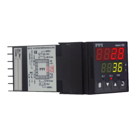
PPI neuro 102 User manual
PPI
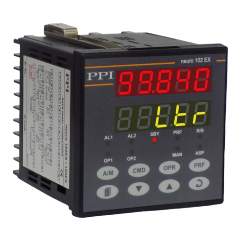
PPI Neuro 102EX User manual

PPI
PPI neuro 102Plus User manual
PPI
PPI neuro 102L Plus User manual
PPI
PPI HumiTherm Plus User manual
PPI
PPI HumiTherm-c Series User manual
PPI
PPI neuro 202 User manual

PPI
PPI neuro 102 EX User manual

PPI
PPI neuro 105 User manual
PPI
PPI Epsilon 48 User manual
Popular Controllers manuals by other brands
Siemens
Siemens SIRIUS 3RW40 operating instructions
System Studies
System Studies 289 LAN Controller Card Setting up
Kubota
Kubota KF-C3000 Calibration manual
Raco
Raco Schwelm T6C2 Translation of the original instruction

Adjustables
Adjustables MRT2T8-PM Operation guide

Mitsubishi Electric
Mitsubishi Electric Q Series Reference manual
