PPI neuro 105 User manual

Operation Manual
This brief manual is primarily meant for quick reference to wiring
connections and parameter searching. For more details on
operation and application; please log on to www.ppiindia.net
Programmable Profile Controller
neuro 105 48X48
Resolution
Option
Range (Min. to Max.)
0 to +760°C / +32 to +1400°F
-200 to +1300°C / -328 to +2372°F
-200 to +350°C / -328 to +662°F
Fixed
1°C / 1°F
-1999 to +9999 units
-199 to +600°C / -328 to +1112°F
-199.9 to 600.0°C / -199.9 to 999.9°F
or
User settable
1°C / 1°F
or
0.1°C / 0.1°F
User settable
1 / 0.1 / 0.01/
0.001 units
0 to +1770°C / +32 to +3092°F
0 to +1700°C / +32 to +3092°F
+200 to +1700°C / +392 to +3092°F
0 to +1300°C / +32 to +2372°F
J Type T/C
RTD Pt100
0 to 20mA DC
4 to 20mA DC
0 to 50mV DC
0 to 200mV DC
0 to 1.25V DC
0 to 5.0V DC
0 to 10.0V DC
K Type T/C
T Type T/C
R Type T/C
S Type T/C
B Type T/C
N Type T/C
Reserved for customer specific
Thermocouple type not listed
above.
TABLE- 1
Parameters Settings
(Default Value)
INPUT / OUTPUT PARAMETERS : PAGE 12
Parameters Settings
(Default Value)
Output-2 Function
Selection
OP2 & OP3 FUNCTION PARAMETERS : PAGE 14
Parameters Settings
(Default Value)
ALARM PARAMETERS : PAGE 11
Process
Low
Process
High
Deviation
Band
None
Window Band
End of Profile
(Default : None)
Under-range
(PV below Min. Range)
Over-range
(PV above Max. Range)
Message PV Error Type
Open
(Sensor open / broken)
PV Error Indications
Front Panel
101, Diamond Industrial Estate, Navghar,
Vasai Road (E), Dist. Palghar - 401 210.
T: 0250 - 2391722/33/37/42
M: 07498799226
09321985369
Range Low to Range High
(Default : 0)
Alarm
Recorder
Profile Event
(Default : Alarm)
0-20mA
4-20mA
(Default : 0-20mA)
Alarm-1
Deviation Band
Alarm-1 Type
Alarm-1 Setpoint Throughout the range
for the selected input type
(Default : 0)
Alarm-1 Window Band
(Default : Direct)
Direct
Reverse
(Default : None)
None
Process low
Process high
Deviation Band
Window Band
End of Profile
Throughout the range
for the selected input type
(Default : 0)
(Default : Direct)
Direct
Reverse
Alarm-2 Logic
Resolution For PV
Range Low For PV
(Default : 1)
Refer Table 1 for the
available max / min
Ranges & Resolution for
each input type.
-1999 to 9999
(Default : 0)
Digital Filter For PV
Setpoint Low
Offset for PV
Alarm
Cool control
Profile Event
(Default : Alarm)
Output-2 Type
Relay
SSR
0-20mA
4-20mA
(Default : Relay)
Enable
Disable
(Default : Disable)
Quick Adjustment of
Setpoint Enable/Disable
Control Output Type
(Default : Relay)
Relay
SSR
0-20mA
4-20mA
Sensor Input Type
(Default : Type K)
Type J
Type K
Type T
Type R
Type S
Type B
Type N
Reserved
RTD Pt100
0-20mA
0 to 50mV
0 to 200mV
0 to 1.25mV
0 to 5.0mV
0 to 10.0mV
4-20mA
Hand (manual) made
Enable/ Disable
Range High For PV
Output-3 Function
Selection
Select Profile Number
Ramp Hold Band
0 to 250
(Default : 0)
Select Segment Number
1 to twice the
Max. configured Sets
Output-2 Event Time
ON, OFF
(Default : ON)
Parameters Settings
(Default Value)
PROFILE : BAND / EVENT PARAMETERS : PAGE 16
Setpoint High
Setpoint Low to
Setpoint High
(Default : 0)
Control Setpoint
Hysteresis
Cycle Time
Cool Cycle Time
Power Low Limit 0 to less than Power High
(Default : 0)
Relative cool Gain
Greater than
Power Low to 100
(Default : 100)
0 to 250 Seconds
(Default : 25 Sec.)
Parameters Settings
(Default Value)
0 to 999 Units
(Default : 50 units)
Proportional Band
CONTROL PARAMETERS : PAGE 10
Integral Time
Derivative Time
0 to 1000 Seconds
(Default : 100 Sec.)
Power High Limit
Recorder Output Type
Recorder Low
Recorder High
Alarm-1 Hysteresis
Alarm-1 Logic
Alarm-1 Inhibit
Alarm-2 Type
Alarm-2 Setpoint
Alarm-2 Deviation
Band
Alarm-2 Window Band
Alarm-2 Hysteresis
Alarm-2 Inhibit
Soak Hold Band
Output-2 Event Status
Output-3 Event Time
Output-3 Event Status
(Default : Enable)
Enable
Disable
Parameters Settings
(Default Value)
Select Profile Number
1 to Max.
configured
Ramp Rate
Target Setpoint
Range Low to Range High
(Default : 0)
Soak Time
PROFILE : SEGMENT PARAMETERS : PAGE 15
Select Set Number
Profile Enable/Disable
Enable
Disable
(Default : Enable)
Output(S) Off
No
Yes
(Default : No)
Numbers of Profile
1 to 2
Numbers of Sets for
the Selected Profile
1 to 8
No
Yes
(Default : No)
1 to 16
Parameters Settings
(Default Value)
PROFILE : CONFIGURATION PARAMETERS : PAGE 18
Select Profile Number
Number of Programs
Reset Programs Set-UP
1 to Max.
configured
Same as above
(Default : 1000)
NOTE : For Page 17 Kindly Refer the Detailed Manual on
www.ppiindia.net
No
Yes
(Default : No)
1 to Max.
configured
1 to Max.
configured
Parameters Settings
(Default Value)
UTILITY PARAMETERS : PAGE 13
Self Tune Commands
Overshoot Inhibit
Enable
Disable
(Default : Disable)
Baud Rate
1200, 2400,
4800, 9600
(Default : 9600)
Controller ID Number
No
Yes
(Default : No)
Communication Write
Enable
No
Yes
(Default : No)
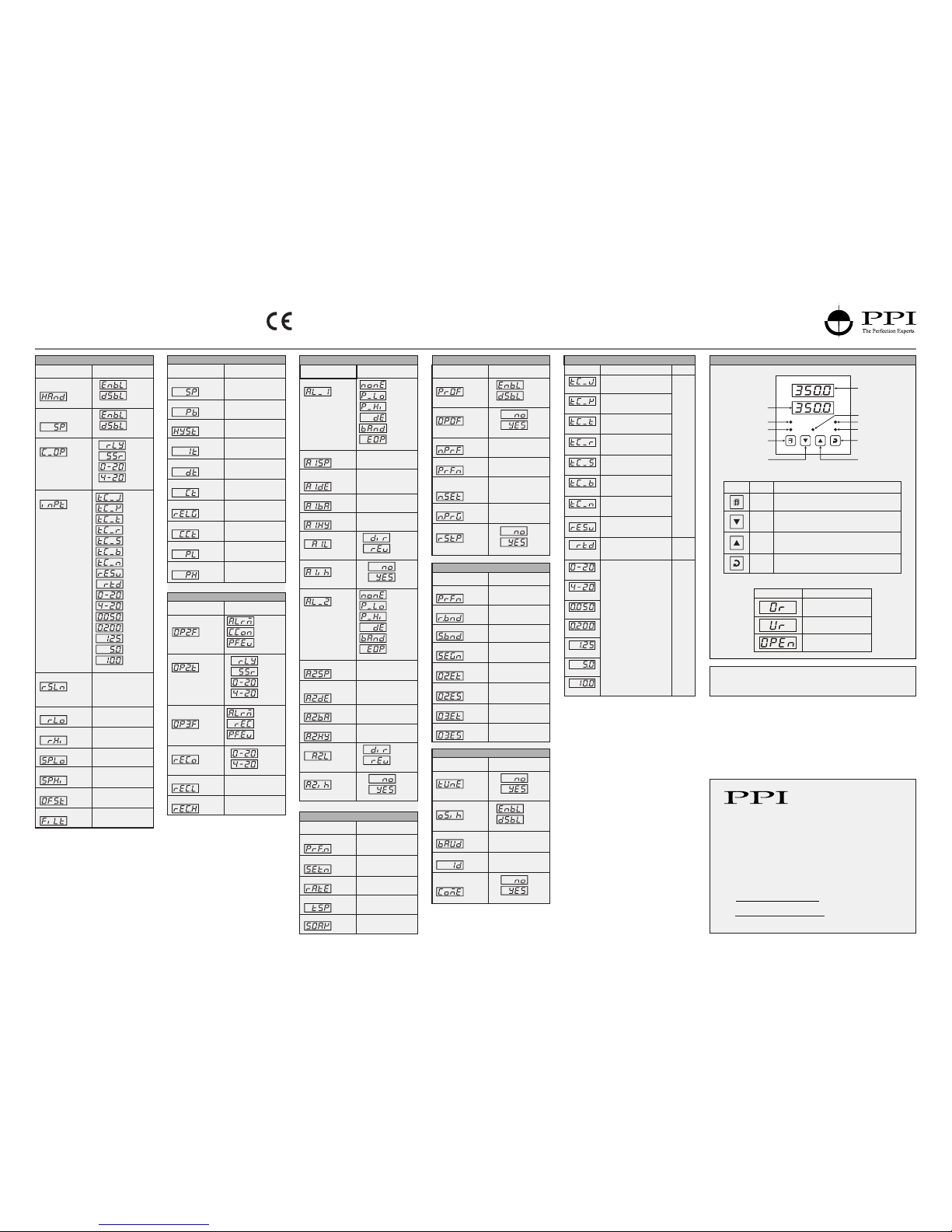
FRONT PANEL LAYOUT
Symbol Key Function
Press to enter or exit set-up mode.
DOWN
UP
ENTER Press to store the set parameter value and to scroll to the
next parameter on the PAGE.
Press to increase the parameter value. Pressing once
increases the value by one count; keeping pressed
speeds up the change.
Press to decrease the parameter value. Pressing once
decreases the value by one count; keeping pressed
speeds up the change.
PAGE
Keys Operation
No
Yes
(Default : No)
0 to 9999
(Default : 0)
0.00 to 99.99
(Default : 0.00)
0 to 250
(Default : 0)
0 to 9999
(Default : 0)
0 to 9999
(Default : 0)
ON, OFF
(Default : ON)
1 to 31
(Default : 1)
Same as above
(Default : -200)
Same as above
(Default : 1300)
Same as above
(Default : 0)
0.5 to 25.0
(Default : 1.0)
1 to 250
(Default : 2)
0.5 to 120.0
(Default : 20.0)
0.1 to 10.0
(Default : 1.0)
0.5 to 120.0
(Default : 20.0)
Range Low to Range High
(Default : 0)
-999 to 999
(Default : 0)
3 to 999
(Default : 3)
1 to 999
(Default : 2)
-999 to 999
(Default : 0)
3 to 999
(Default : 3)
1 to 999
(Default : 2)
PPI
neuro 105
OP1 OP2 OP3
Upper Readout
Lower Readout
Output-3 Indicator
DOWN Key
PAGE Key
Output-1 Indicator
Output-2 Indicator
Ramp Indicator
Soak Indicator
R
S
ENTER Key
UP Key

PPI
Plug & Socket
Connector
Projected
Parts
Slots
Output
Module
Power Supply Board
Front Label Upright
neuro 105
ELECTRICAL CONNECTIONS MOUNTING DETAILS
OUTPUT-2 MODULE
ENCLOSURE ASSEMBLY
Power Supply
PCB
CPU PCB
Display
PCB
‘UP’ inscribed on topside
UP
UP
Placing Back
Removal
Pullout Grip
PPI
neuro 105
OP1 OP2 OP3
R
S
JUMPER SETTINGS
OUTPUT-2 & OUTPUT-3
MOUNTING DETAILS
OUTPUT-3 MODULE
JUMPER SETTINGS
INPUT & OUTPUT-1
MOUNTING DETAILS
Relay/SSR Module
B
A
A
123
B
123
Relay
SSR
2
132
13
2
132
13
Output Type Jumper Setting - A Jumper Setting - B
PPI
Plug & Socket
Connectors
Serial Communication/
Auxiliary SP Selection
Module
Power Supply Board
Front Label
Upside-down
neuro 105
Projected
Parts
Output
Module
PPI
Plug & Socket
Connector
Slots
CPU Board
Front Label
Upside-down
neuro 105
1
2
3
4
5
678910
11
12
13
14
15
16
17
18
NO
C
+
-
RE LAY
SSR / D C Linear
OUTP UT 1
Pt100
T/C
mV, V, mA
INPU T
OUTPU T 2
+
SSR / DC Linear
RE LAY
NO
NC
C
OUT PUT 3
SERIAL
+
SSR / DC Linear
RELAY
NO
NC
C
PPI
L
N
AC
DC
SUPP LY
GND
AUXILIARY SP
SELECTION
A
B
neuro 105
48X48
Input
Link Parked
All Other Input Types
A
CPU PCB
}
}
BA
C
1 2 3
BC
1234
Output 1 Jumper Settings
Input Jumper Settings
PPI
neuro 105
Pins Shorted
DC Linear Current (mA)
ARelay
SSR Drive
1 2 3 4
1 2 3 4
1 2 3 4
1
2
3
1
2
3
1
2
3
DC Linear
Current
(or Voltage)
Output - 1
Output Type Jumper Setting - B Jumper Setting - C
+12V / +5V
SSR / DC Linear
RELAY
OUTPUT 1
mV, V, mA
T/C
INPUT
Pt100
NO C NC
RS 485 85 ~ 265 V
AC SUPPLY
GND
SSR / DC Linear
RELAY
OUTPUT 2
SSR / DC Linear
RELAY
OUTPUT 3
NO
CNC
NO
C
L
N
1
2
3
4
5
13
7
12
8
14
9
15
16
17
11
18
10
6
PPI
Operation Manual
This brief manual is primarily meant for quick reference to wiring
connections and parameter searching. For more details on
operation and application; please log on to www.ppiindia.net
Programmable Profile Controller
neuro 105 96X96
Resolution
Option
Range (Min. to Max.)
0 to +760°C / +32 to +1400°F
-200 to +1300°C / -328 to +2372°F
-200 to +350°C / -328 to +662°F
Fixed
1°C / 1°F
-1999 to +9999 units
-199 to +600°C / -328 to +1112°F
-199.9 to 600.0°C / -199.9 to 999.9°F
or
User settable
1°C / 1°F
or
0.1°C / 0.1°F
User settable
1 / 0.1 / 0.01/
0.001 units
0 to +1770°C / +32 to +3092°F
0 to +1700°C / +32 to +3092°F
+200 to +1700°C / +392 to +3092°F
0 to +1300°C / +32 to +2372°F
J Type T/C
RTD Pt100
0 to 20mA DC
4 to 20mA DC
0 to 50mV DC
0 to 200mV DC
0 to 1.25V DC
0 to 5.0V DC
0 to 10.0V DC
K Type T/C
T Type T/C
R Type T/C
S Type T/C
B Type T/C
N Type T/C
Reserved for customer specific
Thermocouple type not listed
above.
TABLE- 1
Parameters Settings
(Default Value)
INPUT / OUTPUT PARAMETERS : PAGE 12
Parameters Settings
(Default Value)
Output-2 Function
Selection
OP2 & OP3 FUNCTION PARAMETERS : PAGE 14
Parameters Settings
(Default Value)
ALARM PARAMETERS : PAGE 11
Process
Low
Process
High
Deviation
Band
None
Window Band
End of Profile
(Default : )None
Under-range
(PV below Min. Range)
Over-range
(PV above Max. Range)
Message PV Error Type
Open
(Sensor open / broken)
PV Error Indications
Front Panel
101, Diamond Industrial Estate, Navghar,
Vasai Road (E), Dist. Palghar - 401 210.
T: 0250 - 2391722/33/37/42
M: 07498799226
09321985369
Range Low to Range High
(Default : 0)
Alarm
Recorder
Profile Event
(Default : Alarm)
0-20mA
4-20mA
(Default : 0-20mA)
Alarm-1
Deviation Band
Alarm-1 Type
Alarm-1 Setpoint Throughout the range
for the selected input type
(Default : 0)
Alarm-1 Window Band
(Default : Direct)
Direct
Reverse
(Default : None)
None
Process low
Process high
Deviation Band
Window Band
End of Profile
Throughout the range
for the selected input type
(Default : 0)
(Default : Direct)
Direct
Reverse
Alarm-2 Logic
Resolution For PV
Range Low For PV
(Default : 1)
Refer Table 1 for the
available max / min
Ranges & Resolution for
each input type.
-1999 to 9999
(Default : 0)
Digital Filter For PV
Setpoint Low
Offset for PV
Alarm
Cool control
Profile Event
(Default : Alarm)
Output-2 Type
Relay
SSR
0-20mA
4-20mA
(Default : Relay)
Enable
Disable
(Default : Disable)
Quick Adjustment of
Setpoint Enable/Disable
Control Output Type
(Default : Relay)
Relay
SSR
0-20mA
4-20mA
Sensor Input Type
(Default : Type K)
Type J
Type K
Type T
Type R
Type S
Type B
Type N
Reserved
RTD Pt100
0-20mA
0 to 50mV
0 to 200mV
0 to 1.25mV
0 to 5.0mV
0 to 10.0mV
4-20mA
Hand (manual) made
Enable/ Disable
Range High For PV
Output-3 Function
Selection
Select Profile Number
Ramp Hold Band
0 to 250
(Default : 0)
Select Segment Number
1 to twice the
Max. configured Sets
Output-2 Event Time
ON, OFF
(Default : ON)
Parameters Settings
(Default Value)
PROFILE : BAND / EVENT PARAMETERS : PAGE 16
Setpoint High
Setpoint Low to
Setpoint High
(Default : 0)
Control Setpoint
Hysteresis
Cycle Time
Cool Cycle Time
Power Low Limit 0 to less than Power High
(Default : 0)
Relative cool Gain
Greater than
Power Low to 100
(Default : 100)
0 to 250 Seconds
(Default : 25 Sec.)
Parameters Settings
(Default Value)
0 to 999 Units
(Default : 50 units)
Proportional Band
CONTROL PARAMETERS : PAGE 10
Integral Time
Derivative Time
0 to 1000 Seconds
(Default : 100 Sec.)
Power High Limit
Recorder Output Type
Recorder Low
Recorder High
Alarm-1 Hysteresis
Alarm-1 Logic
Alarm-1 Inhibit
Alarm-2 Type
Alarm-2 Setpoint
Alarm-2 Deviation
Band
Alarm-2 Window Band
Alarm-2 Hysteresis
Alarm-2 Inhibit
Soak Hold Band
Output-2 Event Status
Output-3 Event Time
Output-3 Event Status
(Default : Enable)
Enable
Disable
Parameters Settings
(Default Value)
Select Profile Number
1 to Max.
configured
Ramp Rate
Target Setpoint
Range Low to Range High
(Default : 0)
Soak Time
PROFILE : SEGMENT PARAMETERS : PAGE 15
Select Set Number
Profile Enable/Disable
Enable
Disable
(Default : Enable)
Output(S) Off
No
Yes
(Default : No)
Numbers of Profile
1 to 2
Numbers of Sets for
the Selected Profile
1 to 8
No
Yes
(Default : No)
1 to 16
Parameters Settings
(Default Value)
PROFILE : CONFIGURATION PARAMETERS : PAGE 18
Select Profile Number
Number of Programs
Reset Programs Set-UP
1 to Max.
configured
Same as above
(Default : 1000)
NOTE : For Page 17 Kindly Refer the Detailed Manual on
www.ppiindia.net
No
Yes
(Default : No)
1 to Max.
configured
1 to Max.
configured
Parameters Settings
(Default Value)
UTILITY PARAMETERS : PAGE 13
Self Tune Commands
Overshoot Inhibit
Enable
Disable
(Default : Disable)
Baud Rate
1200, 2400,
4800, 9600
(Default : 9600)
Controller ID Number
No
Yes
(Default : No)
Communication Write
Enable
No
Yes
(Default : No)
FRONT PANEL LAYOUT
Symbol Key Function
Press to enter or exit set-up mode.
DOWN
UP
ENTER Press to store the set parameter value and to scroll to the
next parameter on the PAGE.
Press to increase the parameter value. Pressing once
increases the value by one count; keeping pressed
speeds up the change.
Press to decrease the parameter value. Pressing once
decreases the value by one count; keeping pressed
speeds up the change.
PAGE
Keys Operation
No
Yes
(Default : No)
OP1 OP3
neuro 105
PPI
OP2
Upper Readout
Output-3 Indicator
ENTER Key
UP Key
DOWN Key
PAGE Key
Output-1 Indicator
Lower Readout
Output-2 Indicator
RSSoak IndicatorRamp Indicator
0 to 9999
(Default : 0)
0.00 to 99.99
(Default : 0.00)
0 to 250
(Default : 0)
0 to 9999
(Default : 0)
0 to 9999
(Default : 0)
ON, OFF
(Default : ON)
1 to 31
(Default : 1)
Same as above
(Default : -200)
Same as above
(Default : 1300)
Same as above
(Default : 0)
0.5 to 25.0
(Default : 1.0)
1 to 250
(Default : 2)
0.5 to 120.0
(Default : 20.0)
0.1 to 10.0
(Default : 1.0)
0.5 to 120.0
(Default : 20.0)
Range Low to Range High
(Default : 0)
-999 to 999
(Default : 0)
3 to 999
(Default : 3)
1 to 999
(Default : 2)
-999 to 999
(Default : 0)
3 to 999
(Default : 3)
1 to 999
(Default : 2)

ELECTRICAL CONNECTIONS SERIAL COMMUNICATION MODULE
CN3
CN4
Output 3
Jumper Setting
Serial Communication
Module
Power-Supply
PCB
8 Pin Male Plug
8 Pin Female
Socket 123
A
123
B
neuro 105
PPI
INPUT & OUTPUT HARDWARE JUMPER SETTINGS
Input
Thermocouple,
RTD Pt100,
mV & V
DC Linear
Current (mA)
123
Input Type
123
Jumper ‘A’ Setting
Relay
SSR Drive
1 2 3
DC Linear
Current
(or Voltage)
4
3
2
1
4
3
2
1
4
3
2
1
Output Type
1 2 3
1 2 3
Jumper Setting - CJumper Setting - B
Output-2
Output-1
1 2 3 1 2 3
Relay
SSR
Output Type Jumper Setting - EJumper Setting - D
1 2 3 1 2 3
Output-3
1 2 3 1 2 3
Relay
SSR
Output Type Jumper Setting - BJumper Setting - A
1 2 3 1 2 3
Output 1 B & C
Jumper Settings
Input
Jumper Setting
Output 2
Jumper Setting
123
C
13
24
B
123
A
12
D
Display
Keys
}
3123
E
CPU Board
OUTPUT-2
RS485
OUTPUT-3
mV, V, mA
96 X 96
OUTPUT-1
INPUT
SSR/DC Linear SSR/DC Linear
RELAY
NO
C
NC RELAYRELAY
T/C
Pt100
SSR/
DC Linear
NO
C
NC
NO CNC
85 ~ 265 V
AC SUPPLY
N
L
1
2
3
4
5
13
7
12
8
14
9
15
16
17
11
18
10
6
Other manuals for neuro 105
1
Other PPI Controllers manuals


Popular Controllers manuals by other brands

Sanhua
Sanhua MDF-H Series instructions

SOMFY
SOMFY animeo IB+ installation guide

Emerson
Emerson Dixell XR10CX Installing and operating instructions

4IPNET
4IPNET WHG311 Quick installation guide

power automation
power automation PA 9000 installation instructions

Leroy-Somer
Leroy-Somer R448 Installation and Maintenance


CALEFFI
CALEFFI BIOMASS OPTIMISER 1522 Series Installation and commissioning manual

nord
nord NORDAC SK 1 E Series manual

GE
GE IC3645SR7A353T3 Installation and operation manual

sunsei
sunsei CC20000D manual

Siemens
Siemens RDF20U Technical instructions

Siemens
Siemens Powermite 599 Series Technical instructions