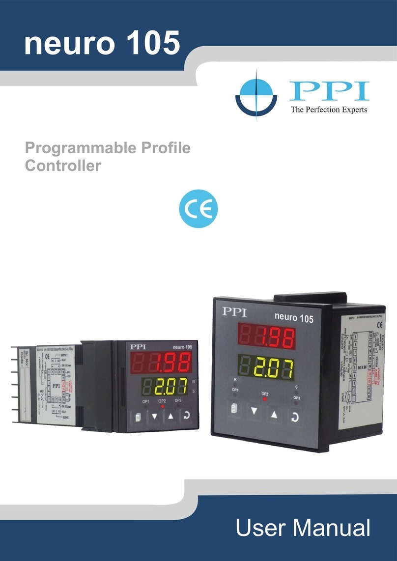
PPI HumiTherm-c Series User manual

(PID)
Composite ‘Temperature + Humidity’
Self Tune PID Controller
Version : Dry-Bulb RTD Pt100, 3-wire
Wet-Bulb RTD Pt100, 3-wire
User Manual
HumiTherm-c
Version : RTD Pt100, 3-wire for Temperature
DC Linear (Voltage) for Humidity

CONTENTS
User Manual
HumiTherm-c
1. FRONT PANEL LAYOUT 1
2. BASIC OPERATION 3
3. PAGES AND PARAMETERS 5
4. TEMPERATURE PARAMETERS 8
5. RELATIVE HUMIDITY PARAMETERS 9
6. SUPERVISORY PARAMETERS 10
7. OP3 FUNCTION PARAMETER 11
8. UTILITY PARAMETERS 12
9. 14COMPRESSOR OPERATION AND POWER INDIC
10. HARDWARE ASSEMBLY & CONFIGURATIONS 15
11. MECHANICAL INSTALLATION 19
12. ELECTRICAL CONNECTIONS 20
1. FRONT PANEL LAYOUT 24
2. BASIC OPERATION 26
3. PAGES AND PARAMETERS 28
4. TEMPERATURE PARAMETERS 31
5. RELATIVE HUMIDITY PARAMETERS 32
6. SUPERVISORY PARAMETERS 33
7. OP3 FUNCTION PARAMETER 34
8. UTILITY PARAMETERS 35
9. 38COMPRESSOR OPERATION AND POWER INDIC
10. HARDWARE ASSEMBLY & CONFIGURATIONS 39
11. MECHANICAL INSTALLATION 43
12. ELECTRICAL CONNECTIONS 44
For Dry-Wet
For Temp+RH

1
Section 1
The controller front panel comprises of digital readouts, LED indicators and tactile keys as shown in Figure 1.1 below.
INDICATORS
There are 5 front panel red LED indicators that show various status. The Table 1.1 below lists each LED indicator (identified by
the front panel legend) and the associated status it indicates.
READOUTS
The Upper Readout is a 4 digit, 7-segment bright red LED display and usually displays the Dry Bulb Temperature Value in °C.
In Program Mode, the Upper Readout displays parameter values.
The Lower Readout is a 4 digit, 7-segment bright green LED display and usually displays Relative Humidity (RH) Value in %.
Upon keeping the UP or DOWN key pressed, the Lower Readout displays Wet Bulb Temperature Value in °C. In Program
Mode, the Lower Readout displays prompts for the parameters.
The indications on the Upper and Lower Readouts, in general, depend on the mode of operation and parameters
configuration. Refer respective sections for more details.
Figure 1.1
Upper Readout
Lower Readout
Alarm-2 Indicator
ENTER Key
UP KeyDOWN Key
PAGE Key
Alarm -1 Indicator
Tune Indicator
Output-1 Indicator
Output-2 Indicator
PPI
HumiTherm-c
AL1 TUN AL2
1
2
°C
%RH
Table 1.1
Indicator Function
Indicates Output-1 (Temperature) control ON/OFF status.
• Glows if the Heater Output is ON.
• Remains OFF if the Heater Output is OFF.
Indicates Output-2 (RH) control ON/OFF status.
• Glows if the Humidification Output is ON.
• Remains OFF if the Humidification Output is OFF.
Indicates Alarm-1 (Alarm for Temperature Loop) status.
• Flashes while the Alarm for Temperature Loop is active.
• Remains OFF while the Alarm for Temperature Loop is inactive.
Indicates Alarm-2 (Alarm for RH Loop) status.
• Flashes while the Alarm for RH Loop is active.
• Remains OFF while the Alarm for RH Loop is inactive.
Indicates Tuning or Compressor ON/OFF status.
• Flashes while the controller is executing the Tuning operation.
• Glows continuously while the Compressor is ON.
• Remains OFF, if not executing the Tuning operation or Compressor is
OFF.
1
2
AL1
AL2
TUN
User Manual
HumiTherm-c (Dry-Wet)
FRONT PANEL LAYOUT

2
KEYS
There are four tactile keys provided on the front panel for configuring the controller and setting-up the parameter values. The
Table 1.2 below lists each key (identified by the front panel symbol) and the associated function.
Table 1.2
Symbol Key Function
Press to enter or exit set-up mode.
DOWN
UP
ENTER Press to store the set parameter value and to scroll to the
next parameter on the PAGE.
Press to increase the parameter value. Pressing once
increases the value by one count; keeping pressed speeds
up the change.
Press to decrease the parameter value. Pressing once
decreases the value by one count; keeping pressed speeds
up the change.
PAGE
User Manual
HumiTherm-c (Dry-Wet)

3
POWER-UP
Upon switching on the power to the controller, all displays and indicators are lit on for approximately 3 seconds during which
time the controller runs through a self-test sequence. This is followed by the indication of the controller model name on
the Upper Readout and the firmware version on the Lower Readout, for approximately 1 second.
MAIN DISPLAY MODE
After the Power-up display sequence, the Upper and Lower Readouts start showing the measured Temperature Value in °C
and the Relative Humidity in %RH, respectively. (The Lower Readout indication may not indicate %RH value if the controller is
configured to operate in ‘Temperature Only’ mode.) This is the MAIN Display Mode and this is the one that shall be used most
often. The MAIN Display Mode is depicted in Figure 2.1 below.
Figure 2.1
Temperature Value
Relative Humidity (RH) Value
PPI
HumiTherm-c
AL1 TUN AL2
1
2
°C
%RH
Upon keeping the UP or DOWN key pressed, the Lower Readout shows the Wet Bulb Temperature in °C.
SETPOINT ADJUSTMENTS
(Refer “Section 3 : Pages & Parameters” for details on Set-up Mode)
For ease of operation, the Temperature and Relative Humidity (% RH) Setpoints (SP) are provided on PAGE-0. The Setpoints
can be adjusted if permitted at supervisory level (PAGE-12). Step through the following sequence to adjust the SP value:
1. Press PAGE key while the controller is in MAIN Display Mode. The Lower Readout shows (PAGE) and the Upper
Readout shows 0.
the Temperature Setpoint, ( .SP), and the Upper
2. Press ENTER key. The Lower Readout shows the prompt for °C
Readout shows the current setpoint value.
Temperature
3. Use UP/DOWN keys to adjust the SP value.
4. Press and release ENTER key. The set value for Temperature Setpoint is registered and stored in the controller’s non-
volatile memory. The Lower Readout shows the prompt for the %RH Setpoint, (rh.SP), and the Upper Readout
shows the current setpoint value.
5. Use UP/DOWN keys to adjust the %RH SP value.
6. Press and release ENTER key. The set value for RH Setpoint is registered and stored in the controller’s non-volatile
memory.
7. Press PAGE key to revert to MAIN Display Mode.
BASIC OPERATIONS
User Manual
HumiTherm-c (Dry-Wet)
Section 2

4
TEMPERATURE-ONLY MODE
The controller can be configured to operate in Temperature-only mode by setting the %RH SP value to 0. In this mode, the
controller controls only the Dry Bulb Temperature at the set value through Heater Control Output-1. The %RH Control Output-
2 is kept off. The Lower Readout in this case can be selected to either display the %RH value (If Wt Bulb RTD sensor is
connected) or the Temperature Unit °C. The parameter (Lower Readout Indication) can be set to ( % R H
indication) or (°C Indication). This selection is available only if %RH SP value is set to 0.
TUNE INDICATION
Upon issuing TUNE command, the controller starts tuning itself to the process under control. While the controller is executing
Tuning operation, the front panel indicator TUN flashes. The user is advised not to disturb the process or alter any parameter
values while the tuning is in progress. The TUN indicator automatically turns OFF upon completion of Tuning Procedure. The
controller reverts to the MAIN Display Mode and starts maintaining the Temperature and RH values (PV) at their respective
Setpoints.
PV ERROR INDICATIONS
The controller indicates the PV error messages for both Temperature and RH Values on Upper and Lower Readout,
respectively, in the following conditions.
Error Indication for Dry Bulb Temperature (Upper Readout)
Figure 2.2 Table 2.1
Message
Over-range
(Dry-Bulb Temp. above Max. Range)
Under-range
(Dry-Bulb Temp. below Min. Range)
Open (Sensor open / broken)
PV Error Type
Error Indication for Relative Humidity (RH) (Lower Readout)
Figure 2.3
Table 2.2
Either Dry Bulb Temp. is below -20.0°C or
above 162.0°C. The error may also occur if
Wet Bulb depression is more then 60.0°C.
Message
Over-range
(Wet-Bulb Temp. above Max. Range)
Under-range
(Wet-Bulb Temp. below Min. Range)
Open (Sensor open / broken)
PV Error Type
User Manual
HumiTherm-c (Dry-Wet)
PPI
HumiTherm-c
AL1 TUN AL2
1
2
°C
%RH
PPI
HumiTherm-c
AL1 TUN AL2
1
2
°C
%RH

5
ORGANIZATION
The controller requires various user settings that determine how the controller will function or operate. These settings are
called Parameters.
The parameters are always presented in a fixed format: The Lower Readout displays the parameter prompt (Identification
Tag) and the Upper Readout displays the set value. The parameters appear in the same sequence as listed in their respective
sections.
For convenience and ease of memorizing, the various parameters have been arranged in different groups depending upon the
functions the parameters represent. Each group is assigned a unique PAGE NUMBER for its access and the parameters
within each group are presented for settings depending upon the function(s) selected.
PROGRAM MODE
The Program Mode allows the user to view or modify the parameter values. The entry from MAIN Display Mode to Program
Mode requires appropriate setting of the PAGE NUMBER. Follow the steps below to open a desired PAGE for setting the
parameter values:
Figure 3.1
PAGES AND PARAMETERS
1. Press and release PAGE key. The Lower Readout shows PAGE and the Upper Readout shows 0. See Figure 3.1.
2. Adjust the Upper Readout to the desired PAGE NUMBER using the UP/DOWN keys.
3. Press and release ENTER key. The Lower Readout shows the prompt for the first parameter listed in the PAGE and the
Upper Readout shows its current value.
Note:
If the entered PAGE NUMBER is invalid (contains no parameter list or any associated function), the controller reverts to the MAIN Display
Mode.
Adjusting Parameter Values
Once a PAGE is accessed, step through the following sequence to adjust the values of the desired parameters:
1. Press and release the ENTER key until the prompt for the desired parameter appears on the Lower Readout. The last
parameter in the list rolls back to the first parameter.
2. Use UP / DOWN keys to adjust the parameter value.
Note that some parameters (examples; ‘Alarm Band’, ‘Proportional Band’, ‘Zero Offset for PV’ etc.) have numeric values
while others (examples; ‘Output-3 Function Selection’, ‘Compressor Control Strategy’, etc.) have a series of options. If
User Manual
HumiTherm-c (Dry-Wet)
Section 3
PPI
HumiTherm-c
AL1 TUN AL2
1
2
°C
%RH

6
adjusting a numeric value; depressing the UP/DOWN key once, increases/decreases the parameter value by one digit.
For parameters having a series of options, depressing the UP/DOWN key once takes you to the next/previous option. In
each case, keeping the UP/DOWN key pressed speeds up the rate. If the value reaches the maximum / minimum settable
value/option, the Upper Readout flashes and the UP (if maximum value is reached) or DOWN (if minimum value is
reached) key has no effect.
3. Press and release the ENTER key. The new value gets stored in the controller’s non-volatile memory and the next
parameter in the list is displayed.
The Figure 3.2 illustrates the example of altering the value for the parameter ‘OP3 Function Selection’.
Figure 3.2
To exit the Program Mode and return to the MAIN Display Mode, press and release PAGE key.
Notes:
If the controller is left in Program Mode for more than 30 seconds without any key operation, the controller automatically exits the Program
Mode and returns to the MAIN Display Mode.
PARAMETER LOCKING
Though access to any PAGE is always permitted, the adjustment of the parameter values, however, can be Locked at the
supervisory level. If the Lock is enabled, the parameter values on each PAGE can only be viewed but can not be adjusted. This
feature facilitates protecting the parameter values from unauthorized tampering or accidental alterations by the operator.
The controller is shipped from the factory in Unlocked condition. The Lock can be enabled once the initial configuration /
installation is done.
For enabling / disabling the Lock, step through the following sequence:
Locking
1. Press and release PAGE key while the controller is in the MAIN Display Mode. The Lower Readout shows PAGE and the
Upper Readout shows 0.
2. Adjust the Upper Readout to the value 123 using UP/DOWN keys.
3. Press and release ENTER key. The controller returns to the MAIN Display Mode with the Lock enabled.
The Figure 3.3 below illustrates the Locking procedure.
Figure 3.3
User Manual
HumiTherm-c (Dry-Wet)
MAIN Display Mode
Return to MAIN
Display Mode

7
Unlocking
1. Press and release PAGE key while the controller is in the MAIN Display Mode. The Lower Readout shows PAGE and the
Upper Readout shows 0.
2. Adjust the Upper Readout to the value 123 using UP/DOWN keys.
3. Press and release ENTER key. The controller returns to the MAIN Display Mode.
4. Repeat steps 1 through 3. This time the controller returns to the MAIN Display Mode with the Lock disabled (Unlocked).
SETTING DEFAULT VALUES
The controller is shipped from the factory with all the parameters set to their default factory set values. If desired, all the
parameters can be reset to default values by following the steps below.
1. Ensure that the controller is Unlocked for parameter adjustments.
2. Press and release PAGE key while the controller is in the MAIN Display Mode. The Lower Readout shows PAGE and the
Upper Readout shows 0.
3. Adjust the Upper Readout to the numeric value 99 using UP/DOWN keys.
4. Press and release ENTER key. The controller resets and restarts from Power-up display sequence with all the parameters
set to their factory set default values.
User Manual
HumiTherm-c (Dry-Wet)

8
The PAGE-10 lists Alarm and Control related parameters for Dry-Bulb Temperature. The Table 4.1 below describes each
parameter.
Table 4.1
TEMPERATURE PARAMETERS
Parameter Description Settings
(Default Value)
(Default : 0.5)
0.3 to 25.0°C
(Default : 0.2)
0.2 to 10.0°C
ALARM-1 BAND
Sets symmetrical positive and negative deviation (offset) limits
from Temperature control setpoint for both High and Low Alarm-1
activation.
Example:
If Band = 0.5°C, then
High Alarm Limit = Setpoint + 0.5°C
Low Alarm Limit = Setpoint - 0.5°C
ALARM-1 HYSTERESIS
Sets differential (dead) band between ON and OFF states of
Alarm-1.
Sets proportional gain (% power per unit error) for temperature
control loop. Defined in same units and resolution as that for PV.
PROPORTIONAL BAND
Sets integral time constant in seconds for temperature control
loop. Setting the value to 0, cuts-off the integral action.
INTEGRAL TIME 0 to 1000 Seconds
(Default : 100)
(Default : 5.0)
0.1 to 999.9°C
(Default : 1.0)
0.5 to 25.0 Seconds
(in steps of 0.5 secs.)
CYCLE TIME
Sets the total ‘On + Off’ time in seconds for time proportional
power output for temperature control loop through Output-1.
DERIVATIVE TIME
Sets derivative time constant in seconds for temperature control
loop. Setting the value to 0, cuts-off the derivative action. (Default : 25)
0 to 250 Seconds
User Manual
HumiTherm-c (Dry-Wet)
Section 4

9
RELATIVE HUMIDITY (% RH) PARAMETERS
The PAGE-11 lists Alarm and Control related parameters for %RH (Wet-Bulb). The Table 5.1 below describes each parameter.
Table 5.1
0 to 1000 Seconds
(Default : 100)
(Default : 10.0)
0.1 to 999.9%
Parameter Description Settings
(Default Value)
0.3 to 25.0%
(Default : 2.0)
0.2 to 10.0%
(Default : 2.0)
ALARM-2 HYSTERESIS
Sets differential (dead) band between ON and OFF states of
Alarm-1.
ALARM-2 BAND
Sets symmetrical positive and negative deviation (offset) limits
from %RH control setpoint for both High and Low Alarm-2
activation.
Example:
If Band = 2.0 % RH, then
High Alarm Limit = SP + 2.0 % RH
Low Alarm Limit = SP - 2.0 % RH
PROPORTIONAL BAND
Sets proportional gain (% power per unit error) for %RH control
loop. Defined in same units and resolution as that for PV.
INTEGRAL TIME
Sets integral time constant in seconds for %RH control loop.
Setting the value to 0, cuts-off the integral action.
(Default : 25)
0 to 250 Seconds
(Default : 1.0)
0.5 to 25.0 Seconds
(in steps of 0.5 secs.)
CYCLE TIME
Sets the total ‘On + Off’ time in seconds for time proportional
power output for %RH control loop through Output-2.
DERIVATIVE TIME
Sets derivative time constant in seconds for %RH control loop.
Setting the value to 0, cuts-off the derivative action.
User Manual
HumiTherm-c (Dry-Wet)
Section 5

10
The Supervisory Parameters provided on PAGE-12 facilitate supervisory control over the operator level. The Table 6.1 below
describes each parameter.
Table 6.1
SUPERVISORY PARAMETERS
BAUD RATE
Communication speed in ‘Bits per Second’. Set the value to match
with the host baud rate.
SP ADJUSTMENT ON PAGE-0
Supervisory permission for Temperature and %RH setpoint
editing on Operator Page (PAGE-0). Set to Enable for permission.
(Default : 1)
1 to 8
(Default : 4800)
ID FOR TEMPERATURE LOOP
Communication ID used by host for temperature value.
(Default : 2)
1 to 8
ID FOR %RH LOOP
Communication ID used by host for %RH value.
(Default : Enable)
Disable
Enable
Parameter Description Settings
(Default Value)
SELF-TUNE COMMAND
Set to ‘Yes’ to initiate a new tuning cycle or set to ‘No’ to abort a
tuning operation in progress. Yes
No
(Default : No)
User Manual
HumiTherm-c (Dry-Wet)
Section 6

11
The OP3 Function Parameters presented on PAGE-13 allow the user to configure the Output-3 (OP3) Function as Alarm or
Compressor Control. The Table 7.1 below describes each parameter.
Table 7.1
OP3 FUNCTION PARAMETERS
Parameter Description Settings
(Default Value)
COMPRESSOR TIME DELAY
(Available if OP3 function is Compressor)
The Time Delay that must elapse before the compressor is
switched ON from OFF state Setting to 0 cuts-off the time delay
function.
COMPRESSOR HYSTERESIS
(Available only if ‘Compressor Control Strategy’ is set to ‘Dry Bulb PV’.)
Sets differential (dead) band between Compressor switching ON
and OFF states. Refer section-8 for details.
(Available only if OP3 function is selected as Compressor)
The setpoint value with which either the Dry Bulb (temperature)
SP or PV is compared for the purpose of switching the compressor
On / Off. Refer section-8 for details.
COMPRESSOR SETPOINT
OUTPUT-3 FUNCTION SELECTION
Select the function / feature to which the OP3 module is to be
logically attached for activation.
0.00 to 10.00 Min. Sec
(in steps of 5 Seconds)
(Default : 00.00)
0.1 to 25.0°C
(Default : 0.2)
(Default : 45.0 or 0.2)
0.0 to 50.0°C or
0.0 to 25.0°C
Alarm
Compressor
(Default : Alarm)
User Manual
HumiTherm-c (Dry-Wet)
Section 7

12
UTILITY PARAMETERS
The Utility Parameters are grouped on PAGE-33 and allow the user to set the Compressor Control Strategy and the Zero-
Offset values for Temperature and the Relative Humidity (RH) values. The Table 8.1 below describes each parameter.
Table 8.1
Dry Bulb SP
Dry Bulb PV
(Default : Dry Bulb SP)
ZERO OFFSET FOR RH VALUE
This value is algebraically added to the measured %RH value to
derive the final PV that is displayed and compared for alarm /
control.
ZERO OFFSET FOR WET BULB
TEMPERATURE VALUE
This value is algebraically added to the measured Wet-Bulb
Temperature value to derive the final PV that is used to compute
the % RH Value.
ZERO OFFSET FOR DRY-BULB
TEMPERATURE VALUE
This value is algebraically added to the measured Dry-Bulb
Temperature value to derive the final PV that is displayed and
compared for alarm / control.
-25.0 to +25.0%
(Default : 0.0)
-25.0 to +25.0°C
(Default : 0.0)
-25.0 to +25.0°C
(Default : 0.0)
Parameter Description Settings
(Default Value)
COMPRESSOR CONTROL STRATEGY
Refer detailed description below.
Compressor Control Strategy
The controller offers two different control algorithms for switching the compressor through Output 3 (OP3) Relay / SSR module
using the parameter ‘Compressor Control Strategy’. The two strategies are explained below. Note that either strategy
operates (switches ON/OFF) the OP3 only if the parameter ‘OP3 Function’ on PAGE-13 is set to ‘Compressor’ and the
‘Compressor Operation Mode ( CP.OP )’ parameter on PAGE-1 is set to ‘Auto’.
1. Dry Bulb SP Strategy
In this strategy, the controller provides two user settable parameters, viz. Compressor Setpoint (CP.SP) & Time Delay
(t.dLY) in PAGE 13 parameter list.
The Compressor ON or OFF state is determined based on the relative position of the Dry Bulb SP (Temperature Setpoint)
with respect to the Compressor Setpoint. If the Dry Bulb SP is below the Compressor Setpoint, the compressor remains ON
and if the Dry Bulb SP is equal or above the Compressor Setpoint, the compressor remains OFF. The following Figures 8.1
and 8.2 illustrate the compressor ON and compressor OFF operation respectively.
User Manual
HumiTherm-c (Dry-Wet)
Section 8

13
Figure 8.1
Compressor ON
Dry Bulb Setpoint (°C.SP)
Compressor Setpoint (CP.SP)
Dry Bulb SP < Compressor SP
Compressor ON
Figure 8.2
Compressor OFF
Dry Bulb Setpoint (°C.SP)
Compressor Setpoint (CP.SP)
Dry Bulb SP ≥ Compressor SP
Compressor OFF
User Manual
HumiTherm-c (Dry-Wet)
This strategy eliminates the dependency on the user for switching off the compressor (for saving valuable electrical energy)
when not required. The Compressor Setpoint for this parameter value is usually set to the maximum expected Ambient
Temperature. It is usually not required to switch-on compressor if the desired Temperature is significantly above the Ambient
Temperature and thus a considerable energy saving can be achieved by keeping the compressor OFF.
2. Dry Bulb PV Strategy
In this strategy, the controller provides three user settable parameters, viz. Compressor Setpoint (CP.SP), Hysteresis
(CP.HY) & Time Delay (t.dLY) in PAGE 13 parameter list. The Compressor ON or OFF state is determined by comparing
the Dry Bulb PV with the Compressor Switch-on Level and the Compressor Switch-off Level. The Compressor Switch-on
and Switch-off levels are determined using Dry Bulb SP (db.SP), Compressor Setpoint (CP.SP) and Hysteresis (CP.HY),
as below.
Switch-on Level = Dry Bulb SP (db.SP) + Compressor SP (CP.SP)
Switch-off Level = Switch-on Level - Hysteresis (CP.HY)
The Hysteresis introduces a dead-band between the Compressor Switch-on Level and Switch-off Level. The following Figure
8.3 illustrates the compressor ON-OFF operation.
Switch-on Level
(Dry Bulb SP + Compressor SP)
Dry Bulb SP
OFF
Hysteresis
ON ON
Switch-off Level
(Switch-on Level - Hysterisis)
Figure 8.3
Examples
1) For Dry Bulb SP = 20.0°C, Compressor SP = 1.0°C & Hysteresis = 1.2°C;
Switch-on Level = 20.0 + 1.0 = 21.0Dry Bulb SP + Compressor SP = °C
Switch-off Level = Switch-on Level - Hysteresis = 21.0 - 1.2 = 19.8°C.
2) For Dry Bulb SP = 20.0°C, Compressor SP = 1.0°C & Hysteresis = 0.8°C;
Switch-on Level = 20.0 + 1.0 = 21.0Dry Bulb SP + Compressor SP = °C
Switch-off Level = Switch-on Level - Hysteresis = 21.0 - 0.8 = 20.2°C.

14
COMPRESSOR OPERATION & POWER INDICATION
The PAGE-1 allows the operator to select the compressor switching as ‘Automatic’ or ‘Manual’, through a parameter
‘Compressor Operation’. This parameter is available and applicable only if the ‘Compressor Control’ is selected for ‘Output-3
(OP3) Function’ in PAGE-13 parameter list. The page also facilitates viewing the PID output powers for both Temperature and
%RH control loops and also Wet-Bulb Setpoint. Refer Table 9.1 below.
Table 9.1
OUTPUT POWER FOR %RH LOOP
OUTPUT POWER FOR
TEMPERATURE LOOP
WET-BULB TEMPERATURE SETPOINT
This value is derived using Dry-Bulb SP & %RH SP.
COMPRESSOR OPERATION MODE
If selected as ‘Auto’, the compressor switching is determined by
the controller based on the setting for the parameter ‘Compressor
Control Strategy’ on PAGE-33.
The ‘Off’ or ‘On’ selection allows the operator to manually switch
the compressor OFF or ON regardless of the ‘Compressor Control
Strategy’. (Default : Auto)
Automatic
Off
On
Parameter Description Settings
(Default Value)
0 to 100.0%
(View Only - Non editable)
0 to 100.0%
(View Only - Non editable)
Within Specified
Temperature Range
(View Only - Non editable)
User Manual
HumiTherm-c (Dry-Wet)
Section 9

15
HARDWARE ASSEMBLY & CONFIGURATIONS
OUTER CASE
The Figure 10.1 above shows the controller outer-case when viewed with controller front label upright. The controller outer
case is a rigid plastic Enclosure into which the electronics assembly fits. The Enclosure in turn fits into the standard DIN size
panel cutout, as described in Section 11 : Mechanical Installation.
Notice the nomenclatures used to identify the various parts as the same are used throughout the sections describing
installation, configuration and electrical connections.
Figure 10.1
UP
UP
Front Label
Pullout Grip
Enclosure
Connection Diagram
Rear Terminals Ventilations
Ratchets
Panel Mounting Clamp
Panel Sealing
Gasket
Bezel
PPI
HumiTherm-c
AL1 TUN AL2
1
2
%RH
°C
HumiTherm
1
2
3
4
5
678910
11
12
13
14
15
16
17
18
+5V
OC2
OC1
OUTPUT 1 & 2
Pt100
IN P U T 1
OUTPUT 3
+
RH SENSOR
SERIAL
COMMS.
+
SSR
RELAY
N/O
N/C
C
PPI
L
N
AC
DC
SUPPLY
-
Ex
INPUT 2
_
ELECTRONIC ASSEMBLY
The electronic assembly can be removed from the plastic Enclosure and placed back as described below and illustrated in
Figure 10.2
Removal
1. Hold the controller with its front label upright.
2. Hold the Bezel with the fingers on the pullout grips provided on the left and right sides of the bezel. Pull the bezel outward.
The assembly comes out with the bezel.
User Manual
HumiTherm-c (Dry-Wet)
Section 10

16
Figure 10.2.
‘UP’ inscribed on topside
UP
UP
Placing Back
Removal
Pullout Grip
Bezel
Front Label
PPI
HumiTherm-c
AL1 TUN AL2
1
2
%RH
°C
HumiTherm
1
2
3
4
5
678910
11
12
13
14
15
16
17
18
+5V
OC2
OC1
OUT P UT 1 & 2
Pt100
IN P UT 1
OUTPU T 3
+
RH S EN SO R
SERIAL
COMMS.
+
SSR
RELAY
N/O
N/C
C
PPI
L
N
AC
DC
SUP PLY
-
Ex
IN P U T 2
_
Placing Back
1. Hold the bezel with the front label upright.
2. Hold the Enclosure such that the UP inscribed on the Enclosure is on the topside. Insert the bezel gently with the boards on
either side sliding into the guides provided inside of the Enclosure.
3. Ensure that the bezel fits in tight on the Enclosure-front to secure the panel-sealing gasket.
The Figure 10.3 below shows the basic electronics assembly of the controller (without plug-in modules). The basic electronics
assembly comprises of 3 Printed Circuit Boards. As shown in the figure, when viewed from the front, the CPU board is to the
right, Power-supply board is to the left and the Display board is behind the bezel.
Figure 10.3
VIEW
PPI
Power Supply Board
CPU Board
Display Board
Bezel
HumiTherm-c
User Manual
HumiTherm-c (Dry-Wet)

17
MOUNTING PLUG-IN MODULES
The controller supports Input-2 (DC Linear Voltage) module which is mandatary for measuring Relative Humidity (%RH) Value
and two optional plug-in modules, viz. Output-3 (Relay/SSR) module and Serial Communication module. These modules are
either pre-fitted while the controller is shipped from the factory (if ordered with the basic configuration) or can be fitted by the
user if ordered separately. Both the optional modules have female connector (socket) mounted on them, which fit into the
respective male connector (plug) provided on Power-supply board
Output-3 Module
The Output-3 module provides jumper selectable Relay contacts or SSR drive as output. The Figure 10.4 below shows the
output module and the jumper arrangement.
Figure 10.4
As shown in above Figure, there are 2 jumper arrangements marked A and B. The selection between Relay and SSR requires
both these jumpers A and B to be set appropriately as shown in Table 10.1 below. The double headed arrows show the
adjoining Pins that require shorting using the Link.
Table 10.1
Output Type Jumper Setting - A Jumper Setting - B
SSR Voltage
Pulses
Relay
(Arrangement
shown in
Figure 10.4)
The Figure 10.5 below illustrates how to mount the plug-in Output-3 module. Notice the orientation of the controller and a few
identifying components shown in figure to help locate the plug for the module. Ensure that the socket snap-fits into the plug
and the 2 Projections of the module board fit into the 2 Slots provided on the Power-supply board for proper electrical contacts
and secured fitting.
User Manual
HumiTherm-c (Dry-Wet)
Jumper Setting-A
Jumper Setting-B

18
Figure 10.5
Mounting Output-3 Module
PPI
Plug & Socket
Connector
Projections
Slots
Output
Module
Power Supply Board
Front Label Upright
HumiTherm-c
For plugging out the module(s), follow the steps below:
1. Gently pull apart the Power-supply board and the CPU board until the projections of the module board come out of the
slots.
2. Pull the module outward to unlock the socket from the plug.
Serial Communication Module
The plug for the Serial Communication module is located on the Power-supply board. The Figure 10.6 below illustrates how to
plug-in the Serial Communication module. To plug (or unplug) the module simply insert (or remove) the socket into (or from)
the plug.
Mounting Serial Communication Module
Figure 10.6
User Manual
HumiTherm-c (Dry-Wet)
P
PI
Plug & Socket
Connectors
Serial Communication
Module
Power Supply Board
Front Label
Upside-down
HumiTherm-c
This manual suits for next models
3
Table of contents
Other PPI Controllers manuals
Popular Controllers manuals by other brands
Xycom
Xycom XVME-202 manual
Abbey
Abbey swampfox SF1 installation guide
ICM Controls
ICM Controls ICM325HNV Installation, operation & application guide
Zennio
Zennio HeatingBOX 230V 4X Technical documentation

Mitsubishi Electric
Mitsubishi Electric Central Controller G-50A Operation manual
Emerson
Emerson M200-01200024A10101AB100 quick start guide
