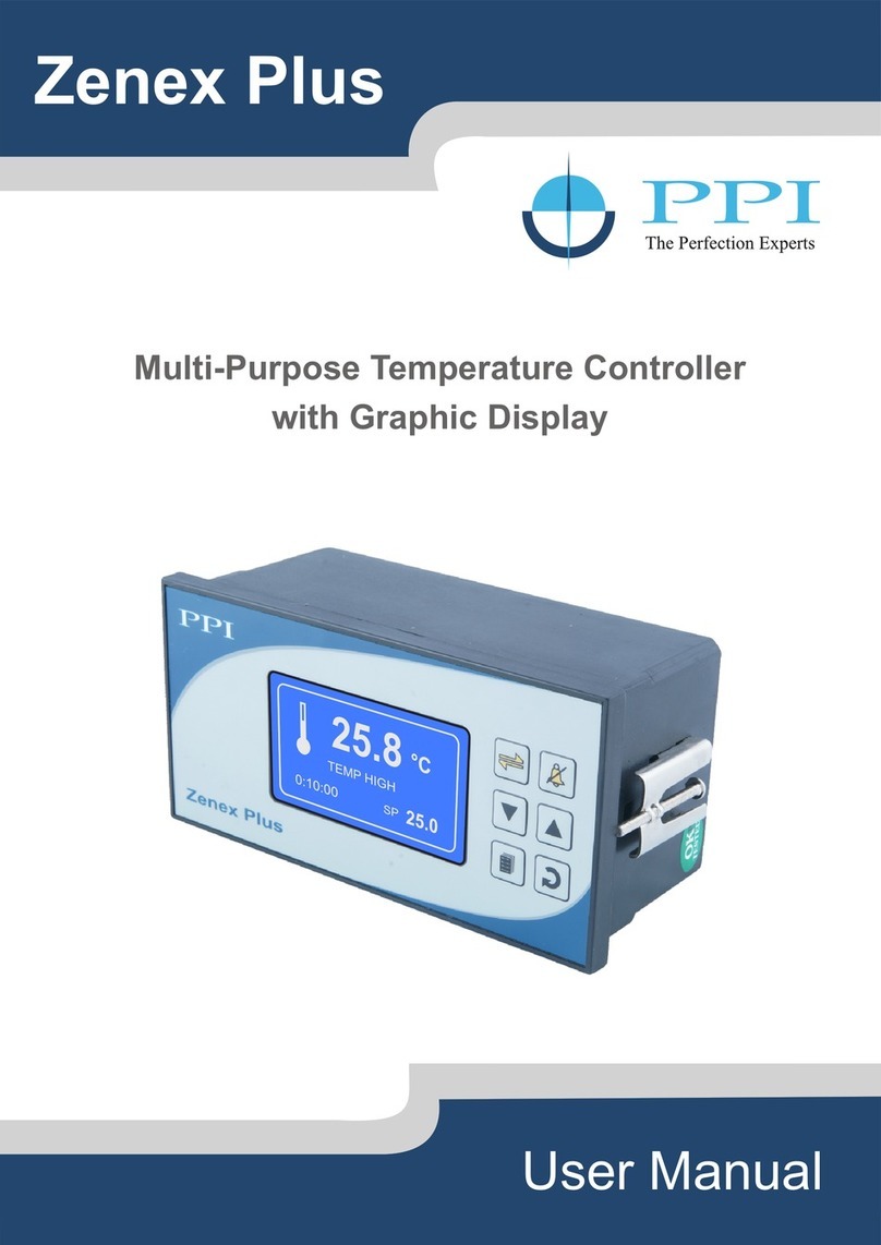
PPI HumiTherm Plus User manual

HumiTherm Plus for PC User Manual
Micro PLC Based Temperature + Humidity (%RH)
Control & Recording System with
21 CFR Part 11 Compliant PC Software
User Manual
3/02/15
10:40:06
°C %RH
25.2 60.3
25.0 60.0
SP SP
HumiTherm Plus
Select Option
Device Wise
Device/Group
HumiLog
Y-Axis Text
Parameter
MIN
MAX
Scale Y Max
Graph Refresh
Interval
2
Set Interval
Channel Name
C
Parameter
Low Alarm
High Alarm
Low Alarm SP
PV
High Alarm SP
Show/Hide
Ledgends
08-05-2015 15:17:59
Parameter Color
PV_C default
default
Close
PV_RH
RH
Control SP
Water Low Level Alarm
Masters Configuration Configuration Online Summary Analysis Report Alarm (4) Data Download User Master Log Out admin
Info Exit
HumiLog
Online Device Comm. Status
Offline Device Comm. Status
Device Comm. Status
1- Humilog - Comm. Success
Device Comm. Status
1- Humilog - IDEAL
History View
x
Online Graph

HumiTherm Plus for PC User Manual
CONTENTS
1. FRONT PANEL LAYOUT 1
2. BASIC OPERATION 2
3. OPERATOR PARAMETERS 5
4. RECORDING PARAMETERS 7
5. FACTORY PARAMETERS 9
6. PANEL MOUNTING AND ELECTRICAL CONNECTIONS 23
APPENDIX-A : DC LINEAR SIGNAL INTERFACE 27

1
HumiTherm Plus for PC User Manual
GRAPHIC READOUT
The Graphic Readout is a 160 X 80 Pixel Monochrome LCD Display. In Normal operation mode the Readout shows measured
Temperature & Relative Humidity (RH) Values besides Date/Time. Other process information like Alarm Status & Control
Status can be viewed using screen scroll feature.
In Set-up Mode, the Readout displays parameter names and values that can be edited using front keys.
KEYS
There are six tactile keys provided on the front panel for configuring the controller and setting-up the parameter values.
The Table 1.1 below lists each key (identified by the front panel symbol) and the associated function.
Section 1
The Controller front panel comprises of Graphic Readout and membrane keys as shown in Figure 1.1 below.
FRONT PANEL LAYOUT
Figure 1.1
Table 1.1
HumiTherm Plus
PPI
°C %RH
3/02/15 10:40:06
25.2 60.3
25.0 60.0
SP SP
Graphic
Readout
Keys
Micro PLC
Symbol
Key Function
DOWN
UP
ENTER
SET-UP Press to enter or exit set-up mode.
Press to store the set parameter value and to scroll to the next
parameter.
Press to increase the parameter value. Pressing once
increases the value by one count; keeping pressed speeds up
the change.
Press to decrease the parameter value. Pressing once
decreases the value by one count; keeping pressed speeds up
the change.
Press to scroll through various Process Information Screens in
Normal Operation Mode.
Scroll
Press to acknowledge and mute (if active) alarm output.
Alarm
Acknowledge

2
HumiTherm Plus for PC User Manual
POWER-UP DISPLAY
BASIC OPERATIONS
Section 2
Upon power-up the controller display shows screen depicted in Figure 2.1(a) for 2 Seconds. The controller runs through a self-
test sequence for checking its Real Time Clock, SD Memory Card, internal Communication Link and Parameter Storage
Memory (EEPROM). The and symbols indicate whether a check is passed or failed, respectively. In case any one or
more checks fail, the controller starts executing its normal operation but ‘Self Checking’ screen is halted until front panel
“Acknowledge” key is pressed. This is followed by screen depicted in Figure 2.1(b) for next 2 Seconds. This screen shows the
controller model name, Hardware Version and Firmware Version.
RUN MODE
After the Power-up display sequence the controller enters into RUN Mode. This is the normal operation mode wherein the
controller starts PV measurements, Alarm monitoring and Control Loop execution. The Display comprises of several screens
described below. The screens appear one-after-the-other upon pressing (Scroll) Key while in RUN Mode.
Main Screen
Figure 2.2
°C %RH
3/02/15 10:40:06
25.2 60.3
25.0 60.0
SP SP
Calendar Date
(Date/Month/Year)
Clock Time
(Hours:Minutes:Seconds)
Measured Humidity
Set Humidity
Alarm / Status Indicator
Measured Temperature
Set Temperature
Figure 2.1 (a)
HumiTherm Plus
H/W Version
F/W Version
01.01
01.01
Figure 2.1 (b)
Self Checking...
SD MEMORY CARD
COMM. LINK
REAL TIME CLOCK
EEPROM
This is the default Run Mode screen that shows Measured Temperature & Humidity Values, Set Temperature & Humidity
Values, Calendar Date, Clock Time and Alarm / Status as illustrated in Figure 2.2 above.
In case of measured value errors for Temperature, the messages listed in Table 2.1 flash in place of process value as
illustrated in Figure 2.3.
°C %RH
3/02/15 10:40:06
OPEN 60.3
25.0 60.0
SP SP
Figure 2.3
Message Error Type Cause
Sensor Open
Under-range
Over-range
Sensor (RTD Pt100) Broken / Open
Temperature above Max. Specified Range
Temperature below Min. Specified Range
OPEN
Table 2.1
OVR
UNR

3
HumiTherm Plus for PC User Manual
In case of measured value errors for %RH (Sensor disconnected or output value below or above specified range), the
measured values are restricted to 0% or 100% depending on signal values.
The ‘Alarm / Status’ space on the screen may show one of the 3 icons listed in Table 2.2 depending upon the existence of
condition. In case of co-existence of multiple conditions, the symbol is indicated based on the associated Indication Priority.
For Example if the controller is operating on Standby Power Source and enters in to Alarm condition, the s y m b o l i s
indicated since it has higher priority over symbol.
Table 2.2
+-
Process Status Screen
Temperature
Alarm Status
Humidity
Alarm Status
Door Status Water Level
Status
°C %RH
PROCESS STATUS
NORMALNORMAL
WTR LVL
NORMAL
DOOR
CLOSE
Figure 2.4
Symbol Indication Priority Condition
Lowest
Normal
Highest The Controller is Self Tuning.
The Controller is operating on Standby
Power Source like battery or inverter.
One or more Alarms are Active.
TUNE
+-
The Process Status Screen is shown upon pressing (Scroll) key from Main Screen or upon acknowledging a new Alarm
by pressing (Acknowledge) key. As depicted in Figure 2.4; the screen shows Temperature Alarm Status, Humidity Alarm
Status, Door Open / Close Status and Water Level Status.
Temperature Alarm Status
The Controller provides programmable Low & High deviation limits around the temperature control setpoint to monitor Alarm
conditions. The screen shows either NORMAL or LOW or HIGH Status, as shown in Figure 2.5 (a) depending upon the
deviation of measured temperature value from the control setpoint and set limits.
°C
NORMAL
Temperature Alarm Status
Within
Limits
Below
Low Limit
Above
High Limit
°C
LOW
°C
HIGH
Humidity Alarm Status
Within
Limits
Below
Low Limit
Above
High Limit
%RH
NORMAL
%RH
LOW
%RH
HIGH
WTR LVL
NORMAL
WTR LVL
LOW
Water Level Status
DOOR
OPEN
DOOR
CLOSE
Door Status
Figure 2.5 (b)Figure 2.5 (a) Figure 2.5 (c)
Figure 2.5 (d)

4
HumiTherm Plus for PC User Manual
Humidity Alarm Status
The Controller provides programmable Low & High deviation limits around the Humidity control setpoint to monitor Alarm
conditions. The screen shows either NORMAL or LOW or HIGH Status, as shown in Figure 2.5 (b) depending upon the
deviation of measured %RH value from the control setpoint and set limits.
Door Status
The Controller provides a Digital Input for interfacing Door switch that senses the door position, Open or Close. The screen
indicates the door status as shown in Figure 2.5 (c).
Water Level Status
The Controller provides a Digital Input for interfacing Float switch that monitors Water for a minimum (Low) Level in steam
generating boiler (humidifier). The screen indicates the water level status as shown in Figure 2.5 (d).
Output Status Screen
Figure 2.6
Heating Humidify
OUTPUT STATUS
5.0%
Compressor
9.0%
ON
Humidity Control
Output Power
Heating Control
Output Power
Compressor
Output Status
The Output Status Screen is shown upon pressing (Scroll) key from Process Status Screen. As depicted in Figure 2.6
above; the screen shows the current value for Air Heater Output (Heating) in %, Steam Boiler Output (Humidify) in % &
Compressor ON / OFF Status.
GSM Status Screen (for GSM Module option only)
GSM STATUS
SimCard
OK
Comm.
OK
Network
OK
Figure 2.7
Comm.
Error
SimCard
Error
The communication link between
the controller & GSM Module is
broken.
The SIM card is either missing or
not inserted properly.
No Network connection.
Network
Error
The GSM Status Screen is shown upon pressing (Scroll) key from Output Status Screen.

5
HumiTherm Plus for PC User Manual
OPERATOR PARAMETERS
The Operator Parameters are accessible under PASSWORD 0. The list includes Parameters for adjusting Control setpoints,
Alarm setpoints & Zero-offset for Temperature & %RH.
The Figure 3.1 shows how to access Operator Parameters. The Example illustrates changing the setpoint value for %RH from
60.0 to 70.0.
Section 3
Parameter Description Settings
(Default Value)
SP Low Limit to
SP High Limit
(Default : 60.0)
%RH SET VALUE >>
Set Value for %RH Control.
Set Value for Temperature Control.
TEMP. SET VALUE >>
Table 3.1
SP Low Limit to
SP High Limit
(Default : 25.0)
The Table 3.1 below described the Operator Parameters in detail.
or
Next Parameter
TEMP. LO DEVIATION >>
2.0
%RH SET VALUE >>
60.0
Desired Parameter
%RH SET VALUE >>
70.0
Desired Value
Press UP/DOWN Keys
to adjust Parameter Value
Press ENTER Key
to store the New Value
& to move to Next Parameter
Figure 3.1
°C %RH
3/02/15 10:40:06
25.2 60.3
25.0 60.0
SP SP
ENTER PASSWORD >>
0
TEMP. SET VALUE >>
25.0
RUN Mode
Main Screen
Default Password
for Operator Parameters
First Parameter
Press SET-UP Key
for Password Entry
Press ENTER Key
To open Operator
Parameter List
Press & Release
ENTER Key until Desired
Parameter appears

6
HumiTherm Plus for PC User Manual
Parameter Description Settings
(Default Value)
0.2 to 99.9
(Default : 2.0)
TEMP. LO DEVIATION >>
This Parameter sets a negative deviation (offset) limit with respect
to the ‘Control Set-point’ for Temperature. The Alarm is activated if
the measured temperature value falls below this limit.
0.2 to 99.9
(Default : 2.0)
TEMP. HI DEVIATION >>
This Parameter sets a negative deviation (offset) limit with respect
to the ‘Control Set-point’ for Temperature. The Alarm is activated if
the measured temperature value exceeds this limit.
0.2 to 99.9
(Default : 2.0)
%RH LO DEVIATION >>
This Parameter sets a negative deviation (offset) limit with respect
to the ‘Control Set-point’ for %RH. The Alarm is activated if the
measured %RH value falls below this limit.
0.2 to 99.9
(Default : 2.0)
%RH HI DEVIATION >>
This Parameter sets a negative deviation (offset) limit with respect
to the ‘Control Set-point’ for %RH. The Alarm is activated if the
measured %RH value exceeds this limit.
CHANGE PASSWORD >>
The Controller is shipped from the factory with a default password
(0) for accessing the parameters reserved for Operator. However,
if required the password can be changed by setting the new value
for this parameter.
(The new password replaces the old password. That is, the old
password is no longer valid. it is user’s responsibility to memorize
the password.)
1 to 100
(Default : )0

7
HumiTherm Plus for PC User Manual
RECORDING PARAMETERS
Section 4
The Recording Parameters are accessible under PASSWORD 123. The list includes Parameters for adjusting Recording
interval, Setting Real Time Clock (RTC), Deleting Records, etc.
The Figure 4.1 shows how to access Recording Parameters. The Example illustrates changing the Recording Interval (first
parameter in the list) from 5 Minutes to 30 Minutes.
ALRM TOGGLE RECORD >>
ENABLE
REC. INTERVAL (MIN)>>
5
First (Desired)
Parameter
REC. INTERVAL (MIN)>>
30
or
Next ParameterDesired Value
Press UP/DOWN Keys
to adjust Parameter Value
Press ENTER Key
to store the New Value
& to move to Next Parameter
Figure 4.1
°C %RH
3/02/15 10:40:06
25.2 60.3
25.0 60.0
SP SP
ENTER PASSWORD >>
0
RUN Mode
Main Screen
Default Password
for Operator Parameters
Press SET-UP Key
for Password Entry
Press UP/DOWN Keys
To adjust Password
Value
Press & Release
ENTER Key for the
First (Desired) Parameter
ENTER PASSWORD >>
123
or
Password for
Recording Parameters
Table 4.1
The Controller generates and stores periodic records at the
interval set by this parameter. The time units are in Minutes.
Setting this parameter value to 0 disables normal recording.
RECORDING INTERVAL (MIN) >>
If this parameter is set to ‘Enable’, the Controller generates and
stores a record each time either the temperature or %RH alarm
toggles the status (On-to-Off or Off-to-On).
ALARM TOGGLE RECORDS >> ENABLE
DISABLE
(Default : ENABLE)
(Default : )5 Min
0 to 250 Min
Parameter Description Settings
(Default Value)
DELETE PC RECORDS >>
This parameter is a command that allows the user to delete all the
records from the controller memory that are meant for uploading
to remote PC. Set the parameter to “YES” to carry out delete
operation.
YES
NO
(Default : NO)

8
HumiTherm Plus for PC User Manual
Parameter Description Settings
(Default Value)
0 to 23 for Hour
0 to 59 for Min
(Default : NA)
RTC TIME >>
Set current clock time in Hrs:Min (24 Hours format).
1 to 31
(Default : NA)
RTC DATE >>
Set current calendar date.
1 to 12
(Default : NA)
RTC MONTH >>
Set current calendar month.
2000 to 2099
(Default : NA)
RTC YEAR >>
Set current calendar year.
1 to 127
(Default : 1)
DEVICE ID >>
(Applicable for Serial Communication)
Unique numeric code assigned to the indicator for identification by
the remote PC. Set the value as required by the remote PC.
1000 to 1999
(Default : 123)
CHANGE PASSWORD >>
The Controller is shipped from the factory with a default password
(123) for accessing the parameters reserved for Supervisor.
However, if required the password can be changed by setting the
new value for this parameter.
(The new password replaces the old password. That is, the old
password is no longer valid. it is user’s responsibility to memorize
the password.)
1 to 128
(Default : 1)
GSM MACHINE ID >>
(Available only if the controller is supplied with GSM Module
Version)
This parameter can be used to assigned a unique ID to the
machine (chamber) to identify the source of SMS alert.
%RH ZERO OFFSET >>
This value is algebraically added to the measured RH Value to
derive the final Value that is displayed and compared for alarm /
control. Use this value to nullify any known constant error.
Final Value = Measured Value + Offset
This value is algebraically added to the measured Temperature
Value to derive the final Value that is displayed and compared for
alarm / control. Use this value to nullify any known constant error.
Final Value = Measured Value + Offset
TEMP. ZERO OFFSET >>
-50.0 to 50.0
(Default : )0.0
-50.0 to 50.0
(Default : )0.0

9
HumiTherm Plus for PC User Manual
Temperature Setting
Alarm Hysteresis, Inhibit
Control
Tune, Set-point Low Limit,
Set-point High Limit,
Proportional Band, Integral
Time, Derivative Time,
Cycle Time
Sensor Input
Input Type, Signal Low,
Signal High, Range Low,
Range High
Compressor Setting Time Delay
Boiler Water Level
Enable/Disable, Water Level
Strategy, Switch - 1 Logic,
Switch - 2 Logic
Humidity Setting
Alarm Hysteresis, Inhibit
Control
Tune, Set-point Low Limit,
Set-point High Limit,
Proportional Band, Integral
Time, Derivative Time,
Cycle Time
Sensor Input
Input Type, Signal Low,
Signal High, Range Low,
Range High
------
------
Door Open
Enable/Disable,
Switch Logic,
Door Alarm Delay
Mains Failure Enable/Disable,
Switch Logic
Factory Default Set to Default Yes/No
Exit Exit Set-up Mode Yes/No
------
------
------
------
FACTORY PARAMETERS
The various parameters have been assembled in groups and sub-groups under the password 321.
Refer Table 5.1 below for a quick summary of parameters under different groups & sub-groups. Each parameter has been
described in subsequent sections.
Section 5
Table 5.1
Sub-Group Parameters
Group
SMS Alert Enable/Disable,
Reset GSM Module
------

10
HumiTherm Plus for PC User Manual
Accessing Group/Sub-group & Parameters
The Figure 5.1 below illustrates how to access the group/sub-group and parameters. The example shows changing the value
for the parameter ‘Proportional Band’ for Humidity Control that is located under group ‘Humidity Settings’ & sub-group
‘Control’.
SELECT >>
ALARM
SELECT GROUP>>
TEMPERATURE SETTING
First Group
or
First Sub-group
Desired Group
Press UP/DOWN
Keys to Select
Desired Group
Press ENTER Key
to Access Sub-group
or Parameters
Figure 5.1
°C %RH
3/02/15 10:40:06
25.2 60.3
25.0 60.0
SP SP
ENTER PASSWORD >>
0
RUN Mode
Main Screen
Default Password
for Operator Parameters
Press SET-UP Key
for Password Entry
Press UP/DOWN Keys
To adjust Password
Value
Press & Release
ENTER Key for the
First Group
ENTER PASSWORD >>
321
or
Desired Password
Desired Sub-group Desired ParameterFirst Parameter in
selected sub-group
SELECT GROUP>>
HUMIDITY SETTING
SELECT >>
CONTROL
TUNE >>
NO
PROPORTIONAL BAND >>
10.0
PROPORTIONAL BAND >>
12.0
or
or or
Press UP/DOWN
Keys to adjust
Parameter Value
First (Desired)
Parameter
Next Parameter
Press UP/DOWN
Keys to Select
Desired Sub-group
Press ENTER Key
to Access Parameters
in selected Sub-group
Press UP/DOWN
Keys to Select
Desired Parameter
Press ENTER Key
to store the Value
and move to Next
Parameter
INTEGRAL TIME >>
100
Notes
1. The Last Parameter in the selected Group or Sub-group rolls back to the ‘SELECT GROUP’ screen again to avoid re-entering the
password in case multiple parameters need to be set under different Group or Sub-group.
2. Select group ‘EXIT’ & set parameter ‘EXIT SET-UP MODE’ to ‘YES’ for returning to Main Display Mode. Alternately use Set-up Key for
instant revert to Main Display Mode.

11
HumiTherm Plus for PC User Manual
For convenience this Temperature Settings group is further divided into 3 sub-groups : Alarm Parameters, Control Parameters
& Sensor Input Parameters.
Parameter Description Settings
(Default Value)
This parameter sets a differential (dead) band between the ON
and OFF Alarm status change. Keep it large enough to avoid
frequent switching of the Alarm Status/Relay.
HYSTERESIS >>
(Default : )0.2
0.1 to 99.9
Yes
The Alarm activation is suppressed until the Temperature value is
within Alarm limits from the time the controller is switched ON. This
allows suppressing the Alarm during the start-up Alarm
conditions.
No
The Alarm is not suppressed during the start-up Alarm conditions.
INHIBIT >>
(Default : )YES
YES
NO
Set ‘Yes’ to activate and ‘No’ to abort the Tuning operation.
Note : The tuning is always performed simultaneously on both
Temperature & Humidity.
TUNE >>
Minimum permissible setpoint value for Temperature control.
SETPOINT LO LIMIT >>
(Default : )10.0
-99.9 to
SETPOINT HI LIMIT
Maximum permissible setpoint value for Temperature control.
SETPOINT HI LIMIT >>
(Default : )NO
YES
NO
(Default : )60.0
For mA/V : SETPOINT LO LIMIT
to 999.9
For RTD : SETPOINT LO LIMIT
to 600.0
Parameter Description Settings
(Default Value)
FACTORY TEMPERATURE ALARM
FACTORY TEMPERATURE CONTROL

12
HumiTherm Plus for PC User Manual
Sets derivative time constant in Seconds for Cool Pre-dominant
zone. Setting the value to 0, cuts-off derivative action.
CZ DERIVATIVE TIME >>
(Default : )16 Sec
0 to 600 Sec
Sets the total ‘On + Off’ time in seconds for time proportional
power output through Relay / SSR.
CYCLE TIME >>
(Default : .0 Sec)10
0.5 to 100.0 Sec
Parameter Description Settings
(Default Value)
Sets proportional gain for Cool Pre-dominant zone.
CZ PROP BAND >>
(Default : )50.0
0.1 to 999.9
Sets integral time constant in Seconds for Cool Pre-dominant
zone. Setting the value to 0, cuts-off integral action.
CZ INTEGRAL TIME >>
(Default : )100 Sec
0 to 3600 Sec
Control Zones : Dual
Sets derivative time constant in Seconds for Heat Pre-dominant
zone. Setting the value to 0, cuts-off derivative action.
HZ DERIVATIVE TIME >>
(Default : )16 Sec
0 to 600 Sec
Sets proportional gain for Heat Pre-dominant zone.
HZ PROP BAND >>
(Default : )50.0
0.1 to 999.9
Sets integral time constant in Seconds for Heat Pre-dominant
zone. Setting the value to 0, cuts-off integral action.
HZ INTEGRAL TIME >>
(Default : )100 Sec
0 to 3600 Sec
Control Zones : Single
Sets derivative time constant in seconds. Setting the value to 0,
cuts-off derivative action.
DERIVATIVE TIME >>
(Default : )16 Sec
0 to 600 Sec
Sets the total ‘On + Off’ time in seconds for time proportional
power output through Relay / SSR.
CYCLE TIME >>
(Default : .0 Sec)10
0.5 to 100.0 Sec
Sets proportional gain (% output power per unit error).
PROPORTIONAL BAND >>
(Default : )50.0
0.1 to 999.9
Sets integral time constant in Seconds. Setting the value to 0,
cuts-off integral action.
INTEGRAL TIME >>
(Default : )100 Sec
0 to 3600 Sec

13
HumiTherm Plus for PC User Manual
FACTORY TEMPERATURE SENSOR INPUT
Parameter Description Settings
(Default Value)
Select Input type in accordance with the type of Temperature
sensor / transmitter connected for measurement.
INPUT TYPE >>
(Available for DC linear V & mA Inputs only)
The transmitter output signal value corresponding to Range Low
process value. Refer Appendix-A : DC Linear Signal Interface for
details.
SIGNAL LO >>
(Available for DC linear V & mA Inputs only)
The transmitter output signal value corresponding to Range High
process value. Refer Appendix-A : DC Linear Signal Interface for
details.
SIGNAL HI >>
(Available for DC linear V & mA Inputs only)
The process value corresponding to the Signal Low value from the
transmitter. Refer Appendix-A : DC Linear Signal Interface for
details.
RANGE LO >>
(Default : 0.0)
-199.9 to RANGE HI
(Available for DC linear V & mA Inputs only)
The process value corresponding to the Signal High value from
the transmitter. Refer Appendix-A : DC Linear Signal Interface for
details.
RANGE HI >>
Input Type Settings Default
0 to 20 mA 0.00 to Signal High 0.00
4 to 20 mA
0 to 5 V
0 to 10 V
1 to 5 V
4.00 to Signal High
0.000 to Signal High
0.00 to Signal High
1.000 to Signal High
4.00
0.000
0.00
1.000
Input Type Settings Default
0 to 20 mA
4 to 20 mA
0 to 5 V
0 to 10 V
1 to 5 V
Signal Low to 20.00 20.00
20.00
5.000
10.00
5.000
Signal Low to 20.00
Signal Low to 5.000
Signal Low to 10.00
Signal Low to 5.000
(Default : 100.0)
RANGE LO to 999.9
(Default : Pt100)RTD
RTD Pt100
0-20mA
4-20mA
0-5V
0-10V
1-5V

14
HumiTherm Plus for PC User Manual
For convenience this Humidity (%RH) Settings group is further divided into 3 sub-groups : Alarm Parameters, Control
Parameters & Sensor Input Parameters.
Parameter Description Settings
(Default Value)
This parameter sets a differential (dead) band between the ON
and OFF Alarm status change. Keep it large enough to avoid
frequent switching of the Alarm Status/Relay.
HYSTERESIS >>
(Default : )0.2
0.1 to 99.9
Yes
The Alarm activation is suppressed until the %RH value is within
Alarm limits from the time the controller is switched ON. This
allows suppressing the Alarm during the start-up Alarm
conditions.
No
The Alarm is not suppressed during the start-up Alarm conditions.
INHIBIT >>
(Default : )YES
YES
NO
Set ‘Yes’ to activate and ‘No’ to abort the Tuning operation.
Note : The tuning is always performed simultaneously on both
Temperature & Humidity.
TUNE >>
Minimum permissible setpoint value for %RH control.
SETPOINT LO LIMIT >>
(Default : )10.0
-99.9 to
SETPOINT HI LIMIT
Maximum permissible setpoint value for %RH control.
SETPOINT HI LIMIT >>
(Default : )NO
YES
NO
(Default : )60.0
For mA/V : SETPOINT LO LIMIT
to 999.9
For RTD : SETPOINT LO LIMIT
to 600.0
Parameter Description Settings
(Default Value)
FACTORY HUMIDITY (%RH) ALARM
FACTORY HUMIDITY (%RH) CONTROL

15
HumiTherm Plus for PC User Manual
Sets derivative time constant in Seconds for Cool Pre-dominant
zone. Setting the value to 0, cuts-off derivative action.
CZ DERIVATIVE TIME >>
(Default : )16 Sec
0 to 600 Sec
Sets the total ‘On + Off’ time in seconds for time proportional
power output through Relay / SSR.
CYCLE TIME >>
(Default : .0 Sec)10
0.5 to 100.0 Sec
Parameter Description Settings
(Default Value)
Sets proportional gain for Cool Pre-dominant zone.
CZ PROP BAND >>
(Default : )50.0
0.1 to 999.9
Sets integral time constant in Seconds for Cool Pre-dominant
zone. Setting the value to 0, cuts-off integral action.
CZ INTEGRAL TIME >>
(Default : )100 Sec
0 to 3600 Sec
Control Zones : Dual
Sets derivative time constant in Seconds for Heat Pre-dominant
zone. Setting the value to 0, cuts-off derivative action.
HZ DERIVATIVE TIME >>
(Default : )16 Sec
0 to 600 Sec
Sets proportional gain for Heat Pre-dominant zone.
HZ PROP BAND >>
(Default : )50.0
0.1 to 999.9
Sets integral time constant in Seconds for Heat Pre-dominant
zone. Setting the value to 0, cuts-off integral action.
HZ INTEGRAL TIME >>
(Default : )100 Sec
0 to 3600 Sec
Control Zones : Single
Sets derivative time constant in seconds. Setting the value to 0,
cuts-off derivative action.
DERIVATIVE TIME >>
(Default : )16 Sec
0 to 600 Sec
Sets the total ‘On + Off’ time in seconds for time proportional
power output through Relay / SSR.
CYCLE TIME >>
(Default : .0 Sec)10
0.5 to 100.0 Sec
Sets proportional gain (% output power per unit error).
PROPORTIONAL BAND >>
(Default : )50.0
0.1 to 999.9
Sets integral time constant in Seconds. Setting the value to 0,
cuts-off integral action.
INTEGRAL TIME >>
(Default : )100 Sec
0 to 3600 Sec

16
HumiTherm Plus for PC User Manual
FACTORY HUMIDITY (%RH) SENSOR INPUT
Parameter Description Settings
(Default Value)
Select Input type in accordance with the type of %RH sensor /
transmitter connected for measurement.
INPUT TYPE >>
(Available for DC linear V & mA Inputs only)
The transmitter output signal value corresponding to Range Low
process value. Refer Appendix-A : DC Linear Signal Interface for
details.
SIGNAL LO >>
(Available for DC linear V & mA Inputs only)
The transmitter output signal value corresponding to Range High
process value. Refer Appendix-A : DC Linear Signal Interface for
details.
SIGNAL HI >>
(Available for DC linear V & mA Inputs only)
The process value corresponding to the Signal Low value from the
transmitter. Refer Appendix-A : DC Linear Signal Interface for
details.
RANGE LO >>
(Default : 0.0)
-199.9 to RANGE HI
(Available for DC linear V & mA Inputs only)
The process value corresponding to the Signal High value from
the transmitter. Refer Appendix-A : DC Linear Signal Interface for
details.
RANGE HI >>
Input Type Settings Default
0 to 20 mA 0.00 to Signal High 0.00
4 to 20 mA
0 to 5 V
0 to 10 V
1 to 5 V
4.00 to Signal High
0.000 to Signal High
0.00 to Signal High
1.000 to Signal High
4.00
0.000
0.00
1.000
Input Type Settings Default
0 to 20 mA
4 to 20 mA
0 to 5 V
0 to 10 V
1 to 5 V
Signal Low to 20.00 20.00
20.00
5.000
10.00
5.000
Signal Low to 20.00
Signal Low to 5.000
Signal Low to 10.00
Signal Low to 5.000
(Default : 100.0)
RANGE LO to 999.9
(Default : 0-5V)
0-20mA
4-20mA
0-5V
0-10V
1-5V

17
HumiTherm Plus for PC User Manual
FACTORY COMPRESSOR
Compressor Switching Strategies
The PPI “Temperature + Humidity” composite controllers offer different programmable strategies for compressor switching to
meet different design approaches by the manufacturers of Humidity Chambers. The various strategies and the
implementations are described here.
1. Compressor Off
The compressor is kept Off. This strategy is usually selected for temperature values significantly above the ambient
temperature.
2. Compressor On
The compressor is kept On regardless of the measured or set temperature value. This strategy is usually selected for
temperature values significantly below the ambient temperature.
3. SP Based Strategy
In this strategy, the chamber temperature range is split in two zones by setting the parameter 'Boundary Set-point' (BSP).
Refer Figure 5.2 below.
The zone at and above the boundary SP ( ) is referred as Heat Pre-dominant zone and that below the boundary SP ( )
is referred as Cool Pre-dominant zone. The controller automatically switches between the two zones depending upon the
Temperature SP. If the Temperature SP is below boundary SP, Cool Pre-dominant zone is active and the compressor is kept
ON. If the Temperature SP is at or above boundary SP, Heat Pre-dominant zone is active and the compressor is kept OFF. This
strategy eliminates the need for the user to manually switch the compressor ON or OFF.
If the parameter Control Zones is set to “Dual”; separate tuning can be performed in the Cool and Heat Pre-dominant zones for
accurate control in each zone. The controller maintains separate sets of Proportional Band, Integral Time & Derivative Time
constants for each zone that are automatically selected and used by the controller depending upon the active zone.
However, if the parameter Control Zones is set to “Single”; the controller uses a single set of Proportional Band, Integral Time
& Derivative Time constants for both zones.
Figure 5.2
70°C
0°C
45°C
30°C
50°C
Temp. Control SP in
Cool Pre-dominant Zone
Temp. Control SP in
Heat Pre-dominant Zone
Compressor Status
Boundary Set-point
ON
OFF

18
HumiTherm Plus for PC User Manual
4. PV Based Strategy
In this strategy, the compressor is switched to cool down the chamber air temperature. The controller switches the
compressor ON or OFF based on the comparison between the chamber temperature value and the Temperature SP.
Refer Figure 5.3 below.
Figure 5.3
The compressor is turned ON if the chamber air temperature value is above the Temperature SP by an amount set by the
parameter 'Compressor Set-point'. That is;
Compressor Switch - ON Level = (Temperature SP) + (Compressor Set-point)
Once the air temperature falls below Compressor Switch-ON Level by an amount set by the parameter 'Compressor
Hysteresis', the compressor is turned OFF. That is;
Compressor Switch - OFF Level = (Compressor Switch-ON Level) – (Compressor Hysteresis)
The hysteresis inserts a dead band between the Compressor Switch-ON Level and Compressor Switch-OFF Level to avoid
frequent switching of the compressor.
Measured Temperature
Temperature SP
Compressor Switch-ON Level
Compressor Switch-OFF Level
Compressor Switch-ON Level = 20.0 + 1.0 = 21.0°C
Temperature SP = 20.0°C
Compressor Set-point = 1.0°C
Compressor Hysteresis = 1.2°C
Compressor Switch-OFF Level = 21.0 - 1.2 = 19.8°C
Compressor Status
OFF
ON
20.0
19.8
21.0
°C
Compressor Time Delay
Once the compressor is switched off, a time delay is desired before it is turned ON again. The time delay prevents the possible
damage due to short cycling. When the compressor switches off, it spins backward as pressure equalizes. If compressor is
energized while it is still spinning backward, it continues to run backward until it trips on internal overloads. This may cause
damage to the compressor.
The time delay cycle is executed every time the compressor is turned off. The compressor turning off may be a result of power
failure or the on-off control algorithm executed by the controller. The controller in “Auto Mode” monitors the Process Value (PV)
against the Set-Point (SP) and attempts to switch the compressor ON or OFF depending upon whether the PV is above or
below the SP.
The time delay starts counting down from the instance the compressor is switched off. The compressor is inhibited from
switching-on until the delay elapses regardless of the difference between the PV and SP. Once the time delay is elapsed, the
control algorithm switches the compressor ON as and when the PV is above SP.
Figure 5.4
PV (Temperature)
SP
Compressor Switch-ON Level
Compressor Switch-OFF Level
Compressor Switch-ON Level = 20.0 + 1.0 = 21.0°C
Temperature SP = 20.0°C
Compressor Set-point = 1.0°C
Compressor Hysteresis = 1.2°C
Compressor Switch-OFF Level = 21.0 - 1.2 = 19.8°C
Compressor Status
OFF
ON
20.0
19.8
21.0
°C
Case 2 Case 3Case 1
Table of contents
Other PPI Controllers manuals

PPI
PPI Neuro 102EX User manual

PPI
PPI claveX Series User manual

PPI
PPI neuro 105 User manual

PPI
PPI Clavex Pro User manual

PPI
PPI neuro 202 User manual

PPI
PPI Epsilon 48 User manual

PPI
PPI neuro 105 User manual

PPI
PPI Zenex Plus User manual

PPI
PPI neuro 102 EX User manual

PPI
PPI HumiTherm-c Series User manual