Quick Start Guide, 61700530F1-13D, April 2014 1
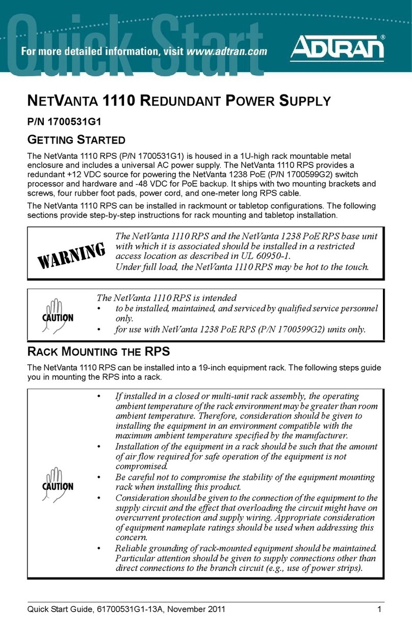
NETVANTA 1131 REDUNDANT/EXTENDED POWER SUPPLY
P/N 1700530F1, 1700532F1 (RPS CABLE), 1700533F1 (EPS CABLE)
4 Copyright © 2014 ADTRAN, Inc. All Rights Reserved.
GETTING STARTED
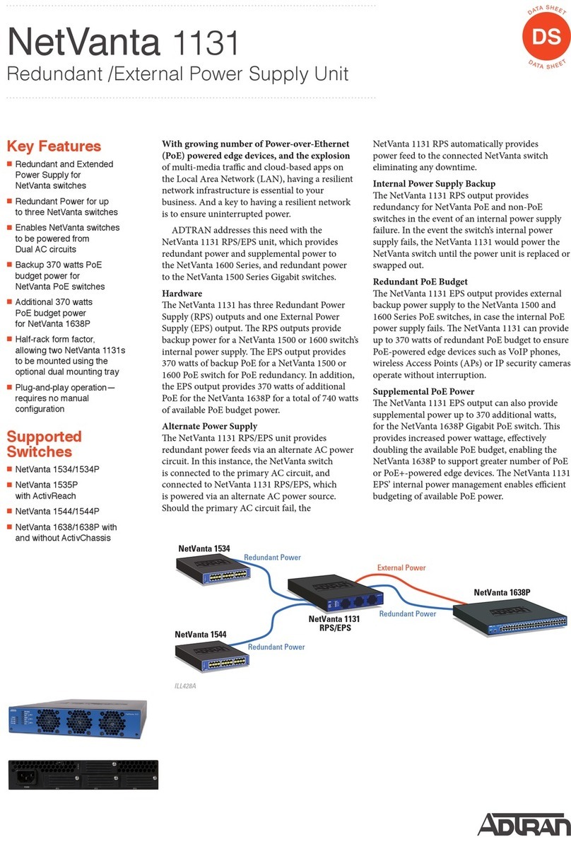
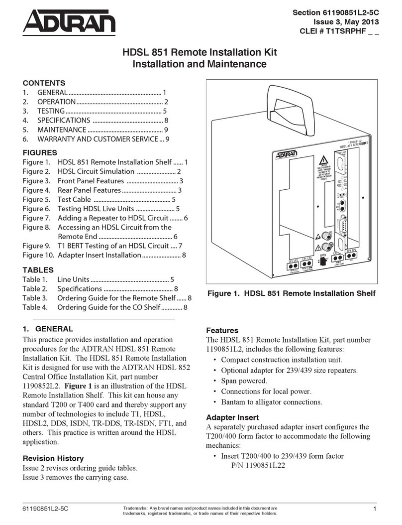
The NetVanta 1131 RPS/EPS has three RPS outputs and one EPS output for use with RPS/EPS
equipped NetVanta switches. Important: Refer to the NetVanta 1131 product on www.adtran.com
for a list of supported switches. The RPS outputs provide redundant or backup power for a
switch’s internal power supply. The EPS output provides backup power for a Power over Ethernet
(PoE) switch’s internal PoE supply, as well as extended or supplemental power to provide full
PoE for 48-port switches (up to 740 W of power).
The NetVanta 1131 does not activate RPS power until a failure is detected on the switch for which
it is providing redundancy. Once RPS power is being supplied to a switch, if a second switch fails,
the power will not transfer to the second switch. In the event that multiple connected switches
lose power simultaneously, RPS power will be supplied to the first failed switch detected.
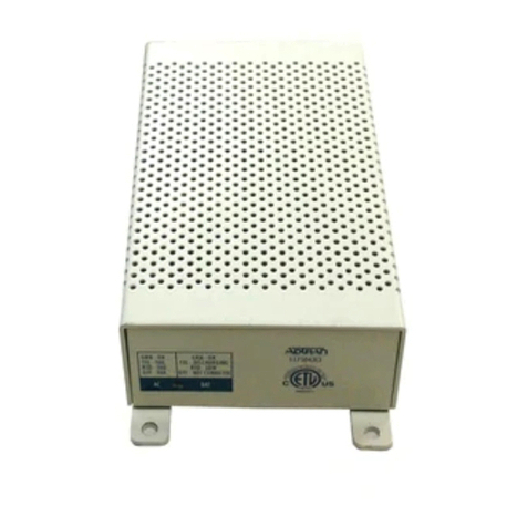
The NetVanta 1131 is housed in a 1U-high, metal enclosure that can be wall mounted, rack
mounted singly using the rackmount brackets, or rack mounted two side by side using the
optional dual mounting tray (P/N 1700534F1).
RACK MOUNTING THE NETVANTA 1131
The NetVanta 1131 can be installed into a 19-inch equipment rack by following these steps:
The NetVanta 1131 and the NetVanta switch with which it is associated
should be installed in a restricted access location as described in
UL 60950-1.
• The NetVanta 1131 is intended to be installed, maintained, and serviced
by qualified service personnel only and is for use with NetVanta
switches only.
• If installed in a closed or multi-unit rack assembly, the operating
ambient temperature of the rack environment may be greater than room
ambient temperature. Therefore, consideration should be given to
installing the equipment in an environment compatible with the
specified 50°C maximum ambient temperature.
• Installation of the equipment in a rack should be such that the amount
of air flow required for safe operation of the equipment is not
compromised.
• Be careful not to compromise the stability of the equipment mounting
rack when installing this product.
• Consideration should be given to the connection of the equipment to the
supply circuit and the effect that overloading the circuit might have on
overcurrent protection and supply wiring. Appropriate consideration
of equipment nameplate ratings should be used when addressing this
concern.
• Reliable grounding of rack-mounted equipment should be maintained.
Particular attention should be given to supply connections other than
direct connections to the branch circuit (e.g., use of power strips).
• This equipment incorporates double pole/neutral fusing. If the neutral
fuse opens and the line fuse does not open, voltage could still be present
in the unit. Line and neutral are provided with fuses for overcurrent
protection.
5. If you plan to use the NetVanta 1131 as an EPS, repeat Steps 1 through 4 using the EPS
cable (P/N 1700533F1 sold separately) and the receptacles labeled EPS located on the rear
panels of the NetVanta 1131 and the NetVanta switch and an EPS cable.
6. To remove an RPS or EPS cable from the unit, pinch the sides of the connector and pull
gently to release it from the receptacle.
7. Proceed to Powering the NetVanta 1131 and the NetVanta Switch.
POWERING THE NETVANTA 1131 AND THE NETVANTA SWITCH
1. Plug the female end NetVanta switch’s power cord (provided with the unit) into the power
receptacle on the rear panel of the unit.
2. Connect the other end (3-prong plug) of the NetVanta switch’s power cord to the proper 110
to 240 VAC grounded receptacle.
3. Plug the female end of the NetVanta 1131 unit’s power cord (provided with the unit) into the
power receptacle labeled Power on the rear panel of the unit.
4. Connect the other end (3-prong plug) of the unit’s power cord to the proper 110 to 240 VAC
grounded receptacle.
LED BEHAVIORS
ADDITIONAL INFORMATION
For additional information about accessing and setting up the NetVanta switch, refer to the
appropriate quick start guide supplied with your unit or online at
https://supportforums.adtran.com.
For additional details on product features, specifications, installation, and safety, refer to
appropriate hardware installation guide available online at https://supportforums.adtran.com.
• This unit shall be installed in accordance with Articles 300 and 400 of
NEC NFPA 70.
• Power to the AC system must be from an appropriately rated and
grounded source.
• Maximum recommended ambient operating temperature is 50oC.
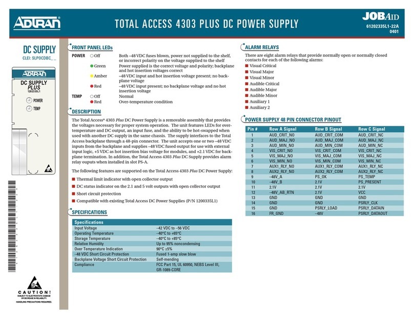
LED Color Indication
Power Off The unit is not receiving power.
Green (solid) The unit is receiving power.
RPS ALM Off The RPS is functioning properly.
Red (solid) The RPS has failed.
EPS ALM Off The EPS is functioning properly.
Red (solid) The EPS has failed.
FAN ALM Off The fans are functioning properly and the system
temperature is acceptable.
Red (solid) The fans have failed.
RPS CONN (1 - 3) Off There is no connection to the switch.
Green (solid) There is a valid connection to the switch.
RPS STAT (1 - 3) Off Power is not being provided to the associated port.
Amber (solid) Power is being provided to the associated port.
Amber (flashing) A fault condition exists on the associated port.
EPS CONN Off There is no connection to the switch.
Green (solid) There is a valid connection to the switch.
