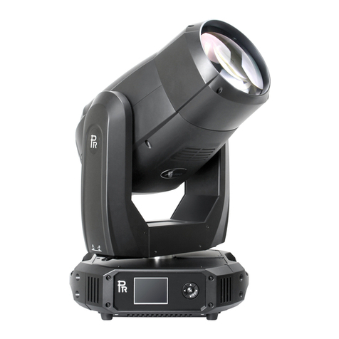
PR Lighting XR580 BWS User manual

2
INDEX
1. SAFETYANDWARNINGS
2. INSTRUCTIONS
●CLEANINGANDMAINTENANCE
●LUBRICATION
●TROUBLESHOOTING
3.APPEARANCE
4.INSTALLATION
●RIGGING
●POWERCONNECTIONS
●DMX CONTROLCONNECTIONS
●DMXTERMINATOR
●ALIGNMENT/INSTALLATION/REPLACEMENTOFALAMP
●GOBO/COLOR FILTERREPLACEMENT
5.SETUPANDCONFIGURATION
●FRONTPANELOPERATION
●DMX STARTADDRESS
●DMXWIRELESS CONTROL
●STAND-ALONEMODE
●MASTER/SLAVEMODE
6.OPERATION MENU
7.DMXPROTOCOL
8.LOGOS
9.ERRORMESSAGES
10.TECHNICALDATA
11.CIRCUITDIAGRAMANDPCB CONNECTIONS
●CIRCUITDIAGRAM
●PCB CONNECTIONS
12.COMPONENTORDER CODES
3
4
4
4
4
5
5
6
6
7
7
8
8
9
9
9
9
10
10
10
15
19
19
20
25
25
26
27
ACCESSORIES
The following itemsare suppliedwith the projectorandplease check:
Name
Quantity
Unit
Remark
Gclamps
2
Pcs
XLR connector
1
Set
Male andfemale
Safetycord
1
Pc
User manual
1
Pc
Ω clamps
2
Pcs
Optional
Please note that as part of our ongoing commitment to continuous product development, specifications are
subject to change without notice. Whilst every care is taken in the preparation of the manual we reserve the
right to change specifications in the course of product improvement. The publishers cannot be held responsible
for the accuracy of the information herein, or any consequence arising from them.
Every unit is tested completely and packed properly by the manufacturer. Please make sure the packing and /
or the unit are in good condition before installation and use. Should there be any damage caused by
transportation, consult your dealer and do not use the unit. Any damage caused by improper use will not be
assumed by the manufacturer and / or dealer.
Note: Forthe products made by GuangzhouPR lighting Ltd, the warranty forthe whole product is one yearstarting from
the delivery date butthe light sourceisnotwithinthewarranty.

3
1. SAFETYANDWARNINGS
NOTE
Before a projector’s installation, power-on, operation and maintenance, please carefully read
thesafety informationhereinafter!
Thefollowingsafetysignsareused inthe usermanual.
Warning
User
Manual
Electrical
shock
Goggles
Protective
Gloves
Flames
High
Temperature
● When unpacking , checkif there is transportationdamage before using the projector. Should there be any
damagecausedbytransportation,consultyourdealeranddonotuseit.
●The manufacture is not responsible for loss caused bythe user not following the manual or changing the projector
ashe/shelikes.
●Pleasebe noted that thedamagecausedbychangingtheprojector at willis notwarranted.
●Do not hesitate to contact the dealer or the manufacturer if any questions or advice.
● Theprojector is forindooruseonly,IP20.
● Use only in drylocations. Keep this unit away from rain and moisture, excessive heat, humidity and dust. Do not
allowcontactwith wateroranyother liquids.
●The projector should be kept away from high temperature, fire, electrical surge, vibration and strong light while
beingoperated.
●The projector is only intended for installation, operation and maintenance by qualified personnel. And the
operationmuststrictlyfollowtheproceduresinthemanual.
●Norepairable partsinthe projector anddo notopencoversformaintenance byyourself.
●Don’t look straightly into the light sources especially for epileptics, otherwise eyes will be burned..
●Donotconnectthisdevicetoanytypeofdimmer pack.
●After lampswitched on,theminimum distancebetweentheprojectorandilluminated surfaceis18 m.
●lensandotheropticalpartsshallbe replacedimmediatelyifthey havedeformedor beendamaged,otherwisethe
lightoutputwill becompromised.
●Before operation, please confirm that all covers(housing) are on and screws tightened. It’s forbidden to use a
projector whilecovers(housing)areoff.
●Keep thelamp cleananddo not touchitwithbarehands.
●Whileoperatingit,wearprotective items.
●Any electricalconnection mustbe carried outbyaqualifiedperson.
●Beforeinstallation,pleaseconfirmthevoltagesupplied matches whatisrequired forthe projector.
●Eachprojector mustbeproperlyearthedand installed asper relatedelectricalstandards.
●Do not use power cord withits insulator damaged and connectthepowercord withothercables.
●If the projector is not used or under cleaning,, please hold the plug and unplugit. Do not unplug it forcefully
orbypullingthe power cable.
●Allpowercordsmustconform torelatedsafetyand regulations.
●Whilebeingoperated,theprojectorshould notbeunderrainsorinhumidity.
●Do not switch on and off the projector constantly in very short intervals, otherwise the light source’s and other
electricalparts’ life will be shortened .

4
●There are safety cord holes at the bottom of the base of a projector. In view of safety, please run the safety
cord supplied throughthe safetycord holesfor safetysupport.
●Before any installation, maintenance and cleaning work, please ensure the projector is disconnected from
powermains.
●After runningfor 30minutes, thetemperature ofthe housingoftheprojector is 45℃.Afterstableoperation ,
its max.temperatureis120℃.
●Whilethelamp isstrickenfor the firsttime,there willbesmokeand strangesmell.It’s normal and does not
meantheprojectorhassome defects.
●Donot mounttheprojector directlyoninflammablesurface.
●Donotproject thebeamstraightlyoncombustibleitems andtheminimumdistancebetweentheprojector
andilluminateditemsis18 m.
●Aprojector should be installed with good ventilationand the minimum distance between the projector and
wallsis50cm.Atthesame time,pleaseensurethe fansandairinletsandoutlets are workable.
2. INSTRUCTIONS
●CLEANINGANDMAINTENANCE
If a projector can’t start. Please check if the fuse is blown up. If it does, replace it with a new fuse with same ratings. And the
projector has over-temperature protective device. If the temperature is too high, the protective device will be triggered to shut the
projector off. When it happens, please check if the fans run normally or fan shield is blocked by dust. After the issue is solved,
restart theprojector.
The accumulationof oil, smoke and dust on the lenswill compromise the light output. Cleaning a projector is verynecessary to
ensure areliable use of it. Cooling fans need to be cleaned every15days. Internal lens, reflectorand hotmirror need to be cleaned
periodically tooptimize lightoutput.
Cleaning frequencyis to be decided by operationsand its environment. Use soft clothand normal detergentfor glassfor cleaning
work. It’s advised external optical system be cleaned every 20days and internal optical systems every 30/60days. Keep lens clean
and do not touchoptical parts with bare hands.
●Beforeanymaintenanceandcleaning, pleaseensuretheprojectisoffthepower.
●Onlyqualifiedperson isallowedtodomaintenance.
●During maintenanceandbeforemaintenance, theprojectormustbeoffpower.
●To avoid internal damage, sun light or other light mustn’t penetrate into the projector via front lens
whetheritrunsor not.
●Do not use alcohol or otherorganic solvent to cleanthe housingto avoid damage.
●Do not use anysolvent withchemical elementsto clean colorfiltersor hot mirror.
●LUBRICATION
To ensure smooth movement of gobos and zoom and focus lens, it’s advised rotators’ bearings and 2 sliding bars for zoom and
focuslens be lubricated every2 months. Highqualityand hightemperature lubricant/grease is advised..
●TROUBLESHOOTING
PROBLEM
ACTION
The projector doesn’t switch on
Checkthe fuseonthe powersocket.
Checkthelamp.
Thelampison but the projector doesn’t respond
tothecontroller
Makesurethatthe fixture’s start address is right
ReplaceorrepairtheXLR signalcable.
Theprojectorfunctionsintermittently
Makesurethefanisworkingwellorfansandtheirshieldsarenotblocked
Beamappearsdim, Low inbrightness
Make sure the lamp is within itslifespan
Removedust or grease fromthelenses.
Theprojectimageappearsto haveahalo
Carefullycleanthelamp, opticallensesandothercomponents.
HeavilyDefectiveBeam
Checkif lensare in good condition(not cracked)
5
Cleandustor greaseonthelens.
3. APPEARANCE
1.FrontLens
2.LensCover
3.HeadCover
4.ArmCover
5.Tilt Lock
6.Lamp Chamber Cover
7.BaseHandle
Whiletransportation, the head should be locked-Tilt Lock(5) and Pan Lock(6) should be at locking positions.
Beforetheuse ofthe projector,unlock both.
RearPanelof theBase
1. PowerSwitch
2. FuseHolder
3. PowerSocket
4. 5-PinXLR Socket(Female)
5. 5-PinXLR Socket(Male)
6. EthernetSocket
7. Wireless Antenna(Only for projector
requestedforwirelesscontrol)
FrontPaneloftheBase
1.TouchScreen
2.Escape /Left Key
3.Upkey
4.Down Key
5.Right Key
Touch Screen
Escape/Left Key
Up key
Down Key
Right Key

6
4. INSTALLATION
●RIGGING
Before moving a projector, Please lock Pan and Tilt. Before its operation, please unlock them. It’s forbidden to run a
projectorwithpowerwhileitislocked.
Take 2 clampsand the safetycord out from the package and mount 2 clampson the undersideoffixture with 2 retainers attached
to each clamp. Hang the fixture on the structure and fasten the screws attached to each clamp. (See the WARNING on the
underside of the base as shown above) To passthe SAFETYCORD throughthe HOLES for safety! Always ensure that the
projector is firmly anchored to avoid vibrationand slippingwhilst functioning. Always ensure thatthe structure thatyouare going
tomounttheprojectorto is secureand strongenoughto supporttheweightofaXR1000 Framing.
WARNING:
●TheprojectorMUSTbelifted orcarriedbytheHANDLESinsteadofclamps.
●.For safety the safety cord should afford 10 times the Projector’s weight.
●POWERCONNECTION
Connect thepower cordas follows:
L(live)=brown
E(earth) =yellow/green
N(neutral)=blue
Before power connection, please ensure the power supplied must match what the nameplate says. It is recommended that each
projector be connectedwith powerseparatelyso thattheymaybeindividuallyswitchedonand off.
●The earth wire(yellow/green) must be connected to the ground. And electrical connection must be in
accordancewiththe standardsconcerned.
●Ifany questionsaboutthe electricalinstallation, donotcontinue butconsultaqualifiedelectrician.
Clamp
Control
Panel
Safety cord
Handle
Warning
Please run the safety cord
through the two safety
cord holes to ensure
safety safety cord holes

7
●DMXCONTROLCONNECTION:
Connection between controller and projector and between one projector and another must be made with a twin-screened cable, with
each wire having at least a 0.5mm in diameter. Connection to and from the projector is via cannon5 pin (which are included with the
projector)or5pinXLRplugsandsockets.TheXLR'sare connected asshownin thefigureabove.
Note: care should be taken to ensure that none of the pins touch the metallic bodyof the plug or each other. XLR plugs and sockets
mustn’t be connected in anywayotherthan mentioned in the abovefigure.TheXR330BWS accepts digitalcontrol signals inprotocol
DMX512(1990).
Connect the controller’s DMX output to the first fixture’s DMX input, and connect the first fixture’s DMX output to the second
fixture’s DMX input and connect the rest fixtures in the same way. Eventually connect the last fixture’s DMX output to a DMX
terminatorasshowninthefigurebelow.
●DMXTERMINATOR
In the Controller mode, at the last fixture in the chain, the DMX output has to be connected with a DMX terminator. This prevents
electricalnoise fromdisturbingandcorruptingthe DMXcontrol signals.
The DMX terminator is simply an XLR connector with a 120(ohm) resistor connected across pins 2 and 3, which is thenplugged
into theoutputsocketonthe lastprojector inthechain.The connectionsareillustratedbelow.
Input Output Input Output Input Output DMX
terminator
DMX
controller
21
3
120
DMX TERMINATOR
CONNECTION
Connect a 120 (OHM) resistor
across pins 2 and 3 in an XLR plug
and insert into the DMX out socket
on the last unit in the chain. PIN 3
PIN 2

8
● ALIGNMENT/INSTALLATION/REPLACEMENTOFALAMP
Lock the yoke before fitting/replacingthe lamp. Just as Shown by Figure 1, after Opening the cover at the rear of the projector by
loosening8 fastfit screws, youcanopenthe head.To adjust the lamp asper Figure2.Take out the lampasper the figure 3.
Beforelamp installation,tighten itspower wires well. Lampinand out are oppositeorders
●Don’t touch the internal surface of the reflector and the burner of the lamp with bare hands so as not to
impairthebeamoutput.While lamp’s installation, do not damage the metalwirearoundtheburner.
●Pleaseread"Instructions" enclosed withthelamp
●Do operate the projector while adjusting the lamp
●GOBO REPLACEMENT
DANGER!
Before replacementofgobos, theprojectormustbeoffthe power.

9
5. SETUPANDCONFIGURATION
●FRONTPANELOPERATION
Theprojectorconfigurationcanbesetconveniently viapushbuttonsandcolortouchscreen.
To browse through or change the projector ’s settings, touch the white area of the touch screen or press OK button for more than
3s(Only powered by the battery, pressing the OK button) to unlock the screen , then press ►key to enter the projector ’s function
menus. Each main menu hasits sub-menus. And each menu stands for special function. For the details, please see the following 6th
point ”Operation Menu”.:
1. At the page to set the fixture’s functions, press ◄,►,▲,▼keysortheir respective iconsto select the functionsdesired.
2. While at 2nd,3rd and 4th level of menus, the◄key is for ESCAPE, but ►key won’t work, and OK key is used for ENTER.
Press OK key to save the changes or enter into the sub menus. Press ▲or ▼keys to change the numbers(minus or plus).
Ortouchtheoptionneeded for change.
Shortcut keys: After the Function Menu is entered into, there are all options for the functions on the top of the screen. On the
rightthereare4shortcutkeyslike ←,→Lamp ControlandEnglish/Chinese.
●DMX STARTADDRESS
Eachprojector mustbe givena DMXstart address so that the correctprojector responds to the correct control signals. ThisDMXstart
address is the channel number from which the projector starts to “listen” to the digital control information being sent out from the
controller. The projector has 3DMX modes. There are standard mode ,short mode and extended mode. For example standard mode
has 31 channels, so set the No. 1 projector’s address 001, No. 2 projector’s address 032, No. 3 projector’s address 063,No. 4
projector’s address 094, and soon.
Switch on the Projector . Press OK key more than 3 seconds to unlockpanel, then press ►key to enter into the fixture’s operation
menus.
Select DMX Address icon and press OK key or touch the icon directly on the display and select DMX address at the 2nd level menu
fortheaddresssetting.
Press▲or ▼keysortouch<、>displayed fortheDMXaddressdesired.
PressOKkeytoconfirm.
Pressthe◄key togobackto the upper levelmenu.
.
●DMXWIRELESSCONTROL
The projector has wirelesscontrol functionwith wirelessreceiver module and antennaforremotecontrol.
The setupofitisbelow:
1. Press OK for more than 3s to unlock the control panel, then press ►key to enter into the operation menu and select
“Config Settings”.
2. Select “Wireless First” or “Wireless Only” from the menu of “Signal Select”.

10
Only after the projector is linked with a transmitter, can it receive wireless signal sent by the transmitter. If unlinking it,
Press “Enter” for the menu of Un-link Wirelessunderthe upperlevel menuof ConfigSettigns , thenthe fixture is unlinked
with the wirelesstransmitter.
●STAND-ALONEMODE
Operate the projector without connecting with a controller, enable the master mode through the operation panel, the
projector will run in Stand-Alone mode automatically.
DMX address can be set at any number within 512.
●MASTER/SLAVEMODE
Many projectors can run synchronously in the Master/Slave mode by linking them with each other. First,
connect the first fixture’s DMX output to the second fixture’s DMX input using XLR-XLR controlcable and then connect the second
fixture’s DMX output to the third fixture’s DMX input, and so on until all projector are connected in this way. Eventually connect the
last fixture’s DMX output to a DMX terminator. Set 1st projector as the master and others are Slaves.
StartAddressesofallSlavesare001;Operationmodeof the Master can be set any mode for a Master’ and Slaves’ operation mode can
besetaccordingly.
After Powered on, the group willrunin Master/Slave Mode
6. OPERATION MENU
1stLEVEL
2ndLEVEL
3rdLEVEL
4thLEVEL
5thLEVEL
Address
DMXAddress
1-481
IP Address
DefaultIPAddress
2.X.X.X/10.X.X.X
CustomIPAddress
X.X.X.X
SubNet Mask
X.X.X.X
ArtNetUniverse
0-255
Reset
Total Reset
ReallyReset?
ConfirmorCancel
Pan&TiltReset
ReallyReset?
ConfirmorCancel
ColourSystemReset
ReallyReset?
ConfirmorCancel
GoboReset
ReallyReset?
ConfirmorCancel
Input Output Input Output Input Output DMX
terminator
DMX
controller
Slave Slave
Master

11
Dimmer/Shutterreset
ReallyReset?
ConfirmorCancel
Fo.Fr. Pr.Reset
ReallyReset?
ConfirmorCancel
ConfigSettings
DMXChannelMode
Short Mode
StandardMode
ExtendedMode
ViewSelected Mode
.
LampControl
LampControl
OFF/ ON
On ByPower On
OFF/ ON
Control By DMX
OFF/ ON
EcoPower
OFF/ ON
SignalSelect
XLROnly
XLRFirst
WirelessOnly
WirelessFirst
WirelessIn/XLROut
ARTNETOnly
ARTNETIn/XLROut
LossofDMX
Normaltimeout
Hold LastValue
DisplayConfig
DisplayMode
OffAfterDelay
OnAlways
DisplayInvert
Invert OFF
Invert ON
InvertAuto
LanguageSetting
English\Chinese

12
TemperatureUnit
CelsiusDegree
Fahrenheit Degree
Un-LinkWireless
ReallyUn-Link?
ConfirmorCancel
FactoryDefaults
RestoreDefaults?
ConfirmorCancel
Option Settings
Pan/TiltSettings
PanDMXInvert
OFF/ ON
TiltDMXInvert
OFF/ ON
PanTiltSwap
OFF/ ON
XYFeedback
OFF/ ON
Pan/Tilt mode
Speed/Time
Invert Settings
DimmerInvert
OFF/ ON
CYMInvert
OFF/ ON
Information
ViewDMX Values
Channel Value
Strobe XXX
Dimmer XXX
DimmerFine XXX
CYMMacro XXX
Cyan XXX
Yellow XXX
Magenta XXX
CTO XXX
Color Wheel XXX
Color WheelFine XXX
Fixed Gobo WheelXXX
Rot. GoboWheel XXX
Rot. GoboRotation XXX
Rot. GoboRotation F.XXX
Effect XXX
EffectRotation XXX
Prism1 XXX
Prism1Rotation XXX
Prism2 XXX
Prism2Rotation XXX
Frost XXX
Focus XXX
FocusFine XXX
Zoom XXX
ZoomFine XXX
Pan XXX
Tilt XXX
Pan/TiltSpeed &TimeXXX
Power/SpecialFun. XXX
LampHours
XXX H
Reset Lamp Hours
Total Hours
××××H
Temperature
DisplayBoard=×××C
Pan&Tiltboard=×××C
DriverBoard1=×××C
DriverBoard2=×××C

13
DriverBoard3=×××C
FanDriverBoard=XXXC
HeadSensor=×××C
SoftwareVersion
PCB Sys Boot
DisplayBoard xxx xxx
Pan&Tiltboard xxx xxx
DriverBoard1 xxx xxx
DriverBoard2 xxx xxx
DriverBoard3 xxx xxx
FanDriverBoard=XXXC
ElectronicSN
XXXXXX
RDMDeviceLabel
XR580 BWS
ANSIE1.20RDM
Fan Status
Fan Speed Status
LampFan xxx on/off
LampFan2 xxx on/off
Lamp TFan xxx on/off
LampRFan2 xxx on/off
Head Fan xxx on/off
HeadFan2 xxxon/off
CYM Fanxxx on/off
Gobo Fan xxxon/off
Basic Fan xxx on/off
FanError
Fan Count
LampFan1 xxx
LampFan2 xxx
LampTFan xxx
LampRFan xxx
HeadFan xxx
HeadFan2 xxx
CYM Fanxxx
GoboFan xxx
BasicFan xxx
AccelerationSensor
X Axis:XXX
YAxis:XXX
ZAxis:XXX
Position:XXX
Service
ManualEffectControl
StrobeXXX
DimmerXXX
DimmerFineXXX
CYMMacro XXX
CyanXXX
CyanFine XXX
YellowXXX
YellowFine XXX
Magenta XXX
Magenta FineXXX
CTO XXX
CTOFineXXX
ColorWheelXXX
ColorWheelFineXXX
Fixed GoboWheel XXX
Rot. GoboWheel XXX
Rot. Gobo Rotation XXX
Rot. GoboRotation F.XXX
Effect XXX
Effect Rotation XXX
Prism1 XXX
Prism1 RotationXXX
Prism2XXX
Prism2 RotationXXX

14
Frost XXX
FocusXXX
FocusFineXXX
ZoomXXX
ZoomFineXXX
Pan XXX
Pan FineXXX
TiltXXX
TiltFineXXX
Pan &TiltSpeed &Time
XXX
FactoryMode
…
Operation
Mode
DMXMode
ChangeOperation Mode?
ConfirmorCancel
MasterMode
Preset Memory
ChangeOperation Mode?
ConfirmorCancel
User Memory1
ChangeOperation Mode?
ConfirmorCancel
User Memory2
ChangeOperation Mode?
ConfirmorCancel
Stand-AloneMode
Preset Memory
ChangeOperation Mode?
ConfirmorCancel
User Memory1
ChangeOperation Mode?
ConfirmorCancel
User Memory2
ChangeOperation Mode?
ConfirmorCancel
Static Scene
ChangeOperation Mode?
ConfirmorCancel
DiffFrost
User
Memories
EditUser Memory
EditUser Memory1
/
EditUser Memory2
(1~200Scenes)
SceneXX
(1~200Scenes)
StrobeXXX
DimmerXXX
DimmerFineXXX
CYMMacroXXX
CyanXXX
CyanFine XXX
YellowXXX
YellowFine XXX
MagentaXXX
MagentaFineXXX
CTO XXX
CTOFineXXX
ColorWheelXXX
ColorWheelFineXXX
Fixed GoboWheel XXX
Rot.GoboWheelXXX
Rot. Gobo Rotation XXX
Rot. GoboRotation F.XXX
Effect XXX
Effect RotationXXX
Prism1XXX
Prism1RotationXXX
Prism2XXX
Prism2RotationXXX
Frost XXX
FocusXXX
FocusFineXXX
ZoomXXX
ZoomFineXXX
Pan XXX
PanFineXXX
TiltXXX
TiltFineXXX
Pan &TiltSpeed &Time

15
XXX
FadeTimeXXX
HoldTimeXXX
DelayUnitXXX
LinktoStepXXX
EditStatic Scene
StrobeXXX
DimmerXXX
DimmerFineXXX
CYMMacro XXX
CyanXXX
CyanFine XXX
YellowXXX
YellowFine XXX
Magenta XXX
Magenta FineXXX
CTO XXX
CTOFineXXX
ColorWheelXXX
ColorWheelFineXXX
Fixed GoboWheel XXX
Rot.GoboWheel XXX
Rot. Gobo Rotation XXX
Rot. GoboRotation F.XXX
Effect XXX
Effect Rotation XXX
Prism1 XXX
Prism1 RotationXXX
Prism2XXX
Prism2 RotationXXX
Frost XXX
FocusXXX
FocusFineXXX
ZoomXXX
ZoomFineXXX
Pan XXX
Pan FineXXX
TiltXXX
TiltFineXXX
Pan &TiltSpeed &TimeXXX
FadeTimeXXX
HoldTimeXXX
DelayUnitXXX
LinktoStepXXX
Init User Memory
Reset User Memory1
Reset User Memory?
ConfirmorCancel
Reset User Memory2
Reset User Memory?
ConfirmorCancel
Reset Static Scene
Reset StaticScene?
ConfirmorCancel
7. DMXPROTOCOL
Short
mode
Standard
mode
Extended
Mode
FUNCTION
DMX
DESCRIPTION
1
1
1
Strobe
000-010
Close
011-025
Open
026-225
Strobespeed fromslowto fast
226-246
Randomstrobefrom slowto fast
247-255
Open
2
2
2
Dimmer
000-009
Close
010-255
Lineardimming(0-100%)
3
3
DimmerFine
000-255
Dimmerin16 bit

16
3
4
4
CYMMacro
000-016
White
017-035
Yellow+Magenta=Red
036-054
Yellow
055-073
Yellow+Cyan=Green
074-092
Cyan
093-111
Cyan +Magenta=purple
112-128
Magenta
129-255
CYM color mixingfromslowto fast
4
5
5
Cyan
000-255
Cyan (linear0~100%)
6
Cyan Fine
000-255
Cyan in16Bit
5
6
7
Yellow
000-255
Yellow(linear0~100%)
8
YellowFine
000-255
Yellowin16Bit
6
7
9
Magenta
000-255
Magenta (linear0~100%)
10
Magenta Fine
000-255
Magenta in16Bit
7
8
11
CTO
000-005
No
006-024
Diffuser
025-255
LinearCTO
12
CTOFine
000-255
CTOin16bit
8
9
13
ColorWheel
000-063
Indexing(0-360degrees)
064-068
Color1(Red)
069-073
Color2( LightGreen)
074-078
Color3(Blue)
079-083
Color4(Cyan)
084-088
Color5(Yellow)
089-093
Color6(Magenta)
094-098
Color7(Orange)
099-103
Color8(Green)
104-108
Color9(DeepBlue)
109-113
Color10(UV)
114-118
Color11(LightYellow)
119-123
Color12(DeepYellow)
124-127
White
128-191
Rotation,Clockwisefromslowtofast
192-255
Rotation,Anti-clockwisefromfasttoslow
10
14
ColorWheelFine
0000-255
ColorWheelin16Bit
9
11
15
Fixed Gobo
Wheel
0-19
White
20-25
Gobo1
26-31
Gobo2
32-37
Gobo3
38-43
Gobo4
44-50
Gobo5
51-57
Gobo6
58-64
Gobo7
65-71
Gobo8

17
72-78
Gobo9
79-85
Gobo10
86-92
Gobo11
93-99
Gobo12
100-106
Gobo13
107-113
Gobo14
114-120
Gobo15
121-127
Gobo16
128-157
Clockwiserotation fromslow tofast
158-187
AntiClockwiserotation fromslowtofast
188-191
Shakeeffect 1fromslowtofast
192-195
Shakeeffect 2fromslowtofast
196-199
Shakeeffect 3fromslowtofast
200-203
Shakeeffect 4fromslowtofast
204-207
Shakeeffect 5fromslowtofast
208-211
Shakeeffect 6fromslowtofast
212-215
Shakeeffect 7fromslowtofast
216-219
Shakeeffect 8fromslowtofast
220-223
Shakeeffect 9fromslowtofast
224-227
Shakeeffect 10fromslowtofast
228-231
Shakeeffect 11fromslowtofast
232-235
Shakeeffect 12fromslowtofast
236-239
Shakeeffect 3fromslowtofast
240-243
Shakeeffect14 fromslowto fast
244-247
Shakeeffect 15fromslowtofast
248-251
Shakeeffect 16fromslowtofast
251-255
Shakeeffect 17fromslowtofast
10
12
16
Rotating Gobo
Wheell
000-015
White
016-031
Gobo1
032-047
Gobo2
048-063
Gobo3
064-079
Gobo4
080-095
Gobo5
096-111
Gobo6
112-127
Gobo7
128-156
Rotation (clockwiseFromslowto Fast)
157-185
Reverse Rotation(anti-clockwise From slow to
Fast)
186-195
ShakeofGobo 1fromslow tofast
196-205
ShakeofGobo 2fromslow tofast
206-215
ShakeofGobo 3fromslow tofast
216-225
ShakeofGobo4fromslow to fast
226-235
ShakeofGobo 5fromslow tofast
236-245
ShakeofGobo 6fromslow tofast

18
246-255
ShakeofGobo 7fromslow tofast
11
13
17
Gobo Rotation
000-128
GoboIndexing(0~540degrees)
129-188
Rotation (Clockwise Fromslowto Fast)
189-195
Stop
196-255
Rotation (Anti-ClockwiseFromslowtoFast)
14
18
Gobo Rotation
Fine
000-255
GoboRotation in16Bit
12
15
19
EffectWheel
000-020
No
021-255
EffectWheelIn
13
16
20
EffectWheel
Rotation
000
No
001-127
Rotation (Clockwise Fromslowto Fast)
128-255
Rotation (Anti-ClockwiseFromslowtoFast)
14
17
21
Prism1
000-016
Open
017-127
Prism1
128-255
Prism2
15
18
22
Prism1 Rotation
000-128
Prism Indexing
129-191
Rotation(Clockwisefromslowtofast)
192
Stop
193-255
Rotation(Anti-Clockwisefromslowtofast)
16
19
23
Prism2
000-016
White
017-255
Prism3
17
20
24
Prism2 Rotation
0-130
Prism2 Indexing
131-191
Rotation(Clockwisefromslowtofast)
192-194
Stop
195-255
Rotation(Anti-Clockwisefromslowtofast)
18
21
25
Frost
000-09
No
010-255
FrostIn
19
22
26
Focus
000-255
LinearFocus
23
27
FocusFine
000-255
Focusin16bit precision
20
24
28
Zoom
000-255
LinearZoom
25
29
ZoomFine
000-255
Zoomin16bitprecision
21
26
30
Pan
000-255
Pan(0°~540°)
22
27
31
PanFine
000-255
Panin16bit
23
28
32
Tilt
000-255
Tilt(0°~270°)
24
29
33
TiltFine
000-255
Tiltin16bit
30
34
Pan&TiltSpeeds
000-255
Pan&TiltSpeed fromFastto Slow
25
31
35
Control
000-019
Reserved
Keep in the DMX range for more than 5S to activate the following
functions.Ifpower-off, the following areinvalid.
020-024
Graphic DisplayOn
025-029
GraphicDisplayOff
030-034
Reserved
035-039
Lamp ECOPower
040-044
Lamp FullPower

19
045-089
Reserved
090-094
Pan&TiltSpeed Mode
095-099
Pan&TiltTimeMode
100-129
Reserved
130-139
Lamp On
140-149
Pan&TiltReset
150-159
Color SystemReset
160-169
GoboWheelReset
170-179
Dimmer/Shutter Reset
180-189
Zoom/Frost/Focus/PrismReset
190-199
Reserved
200-209
TotalReset
210-229
Reserved
230-239
Lamp Off
240-255
Reserved
1. The projector can’t be turned on within 1 minute after the lamp-off.
2.Fanerrorcancauselamp-off.
8.Logos
LampControl
OptionSettings
Chinese/English
Information
ErrorMessages
Service
Address
OperationMode
Reset
UserMemories
ConfigSettings
9.Errormessages
Thesystemcandetectsomeerrorsduring thereset,if displayed,touch to viewtheerror.
Theerror messagesare asfollows:
Name
Type
Correction
Pan
Timeout/magnetSensor/Encoder
Checkifwiring,positioningpartsand motors arenormal
Tilt
Timeout/magnetSensor/Encoder
Check ifwiring,positioning parts and motors are normal
Cyan
Timeout
Checkifwiring,positioningpartsand motors arenormal
Yellow
Timeout
Check ifwiring,positioning parts and motors are normal

20
Magenta
Timeout
Checkifwiring,positioningpartsand motors arenormal
CTO
Timeout
Checkifwiring,positioningpartsand motors arenormal
ColorWheel
Timeout
Checkifwiring,positioningpartsand motors arenormal
Fixedgobo wheel
Timeout
Check ifwiring,positioning parts and motors are normal
Rot. GoboWheel1
Timeout
Checkifwiring,positioningpartsand motors arenormal
Rot. Gobo1Rotation
Timeout
Check ifwiring,positioning parts and motors are normal
Dimmer
Timeout
Checkifwiring,positioningpartsand motors arenormal
Prism1
Timeout
Check ifwiring,positioning parts and motors are normal
Prism1Rotation
Timeout
Checkifwiring,positioningpartsand motors arenormal
Prism2
Timeout
Check ifwiring,positioning parts and motors are normal
Prism2Rotation
Timeout
Checkifwiring,positioningpartsand motors arenormal
Focus
Timeout
Checkif wiring, positioningpartsand motors arenormal
Zoom
Timeout
Check ifwiring,positioning parts and motors are normal
LampFan1
Checkiffanand itswiringarenormal
LampFan2
Check iffanand itswiringarenormal
CeramicFan
Error
Checkiffanand itswiringarenormal
CMYFan
Error
Check iffanand itswiringarenormal
HeadFan
Error
Checkiffanand itswiringarenormal
GoboFan
Error
Check iffanand itswiringarenormal
BasicFan
Error
Checkif fan and itswiringarenormal
PanandTiltBoard
Error
Checksignalwire
DriverBoard1
Error
Checksignalwire
DriverBoard2
Error
Checksignalwire
DriverBoard3
Error
Checksignalwire
FanBoard
Error
Checksignalwire
AccelerationSensor
Error
Checksignalwire
Lampon
Timeout
Checkifhelamp isdamaged
LampLife
TimeoutWarning
Lamp Off[Fan
Error]
Error
Checkifallfans arenormal
LapsedTime
Timeout
Time IC
Error
Lapsedtime
Xdays
UsehoursSetting
successfully
10.TECHNICALDATA
ELECTRICPARAMETERS
Inputvoltages100V~240VAC,50/60Hz
InputPower800W@220V
Current at Maximum 8A
This manual suits for next models
1
Table of contents
Other PR Lighting Floodlight manuals

PR Lighting
PR Lighting XLED 1037 PR-8120 User manual

PR Lighting
PR Lighting XRLED PR-8177A User manual

PR Lighting
PR Lighting AQUA LED 1800-W SPOT User manual

PR Lighting
PR Lighting XR 1000 BEAM PR-2723 User manual

PR Lighting
PR Lighting XL 700 User manual

PR Lighting
PR Lighting PR-2935M User manual

PR Lighting
PR Lighting XR 230 SPOT PR-2200 User manual

PR Lighting
PR Lighting PILOT WASH User manual

PR Lighting
PR Lighting AQUA LED 1500-W FRAMING User manual

PR Lighting
PR Lighting PRO STAGE ZOOM PR-3057 User manual