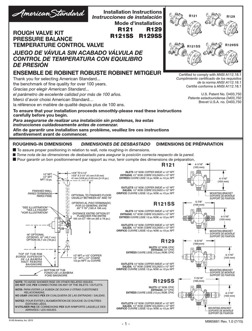
American Standard BAYSPEK047A Assembly instructions
Other American Standard Control Unit manuals

American Standard
American Standard 6047.8 Series User manual

American Standard
American Standard SELECTRONIC 605XTMV1070 User manual
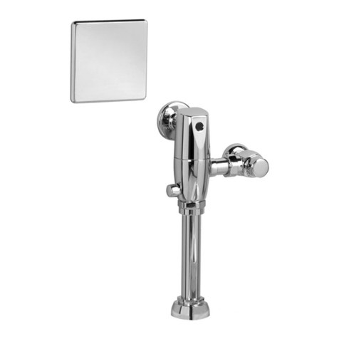
American Standard
American Standard SELECTRONIC 6067.111 User manual
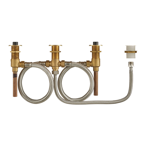
American Standard
American Standard R910 Flash User manual
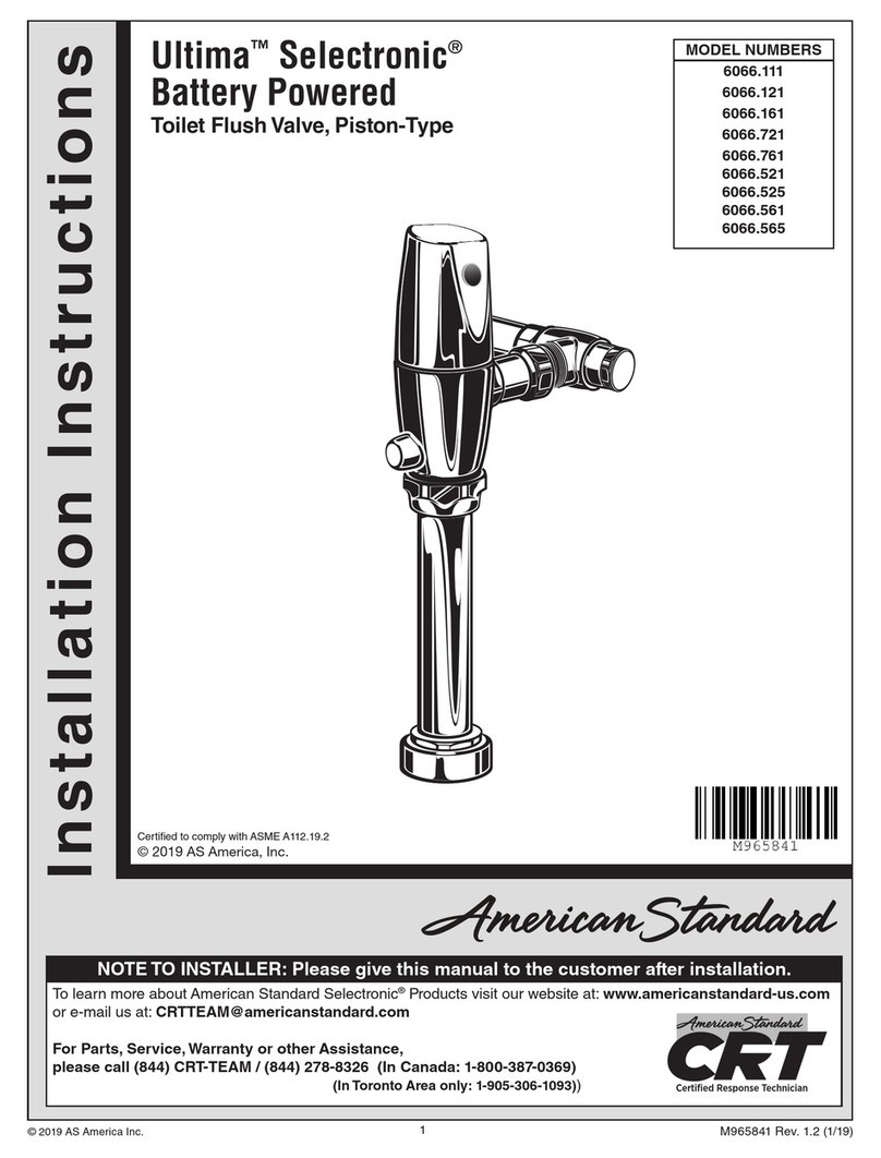
American Standard
American Standard SELECTRONIC 6066.111 User manual
American Standard
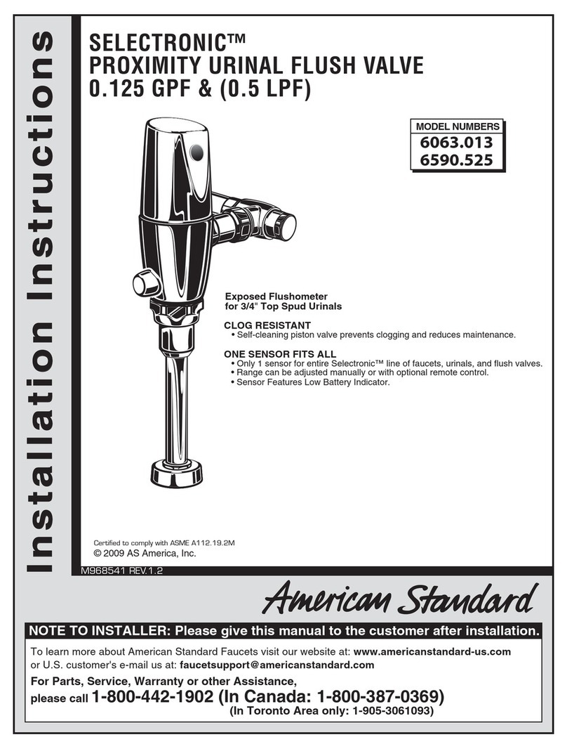
American Standard SELECTRONIC 6590.525 User manual
American Standard
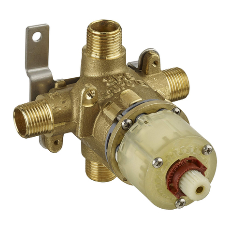
American Standard R111 User manual
American Standard
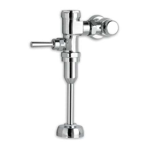
American Standard 6045.101 User manual

American Standard
American Standard ACONT401AN21MA User manual
American Standard
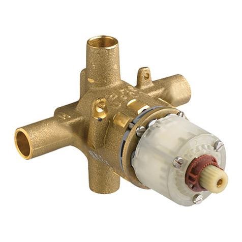
American Standard R110 User manual
American Standard
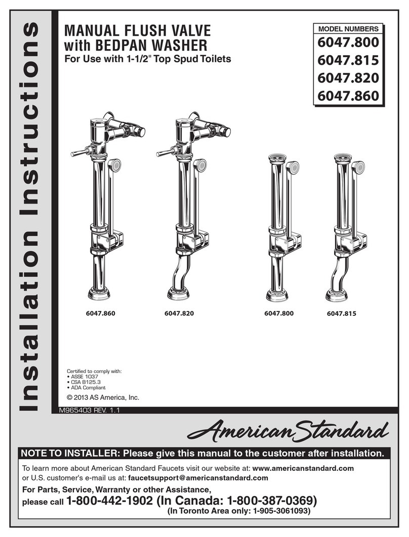
American Standard 6047.800 User manual
American Standard
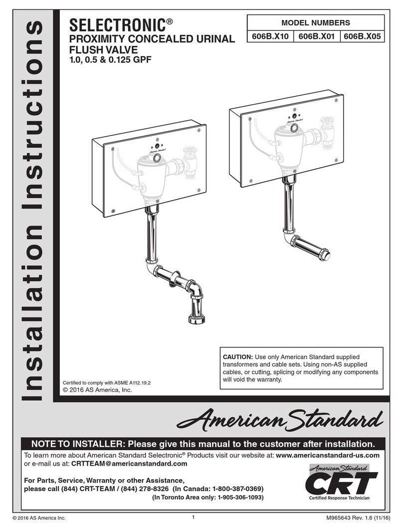
American Standard Selectronic 606B.X10 User manual

American Standard
American Standard Ultima 6147SM User manual

American Standard
American Standard BORNEO User manual
American Standard
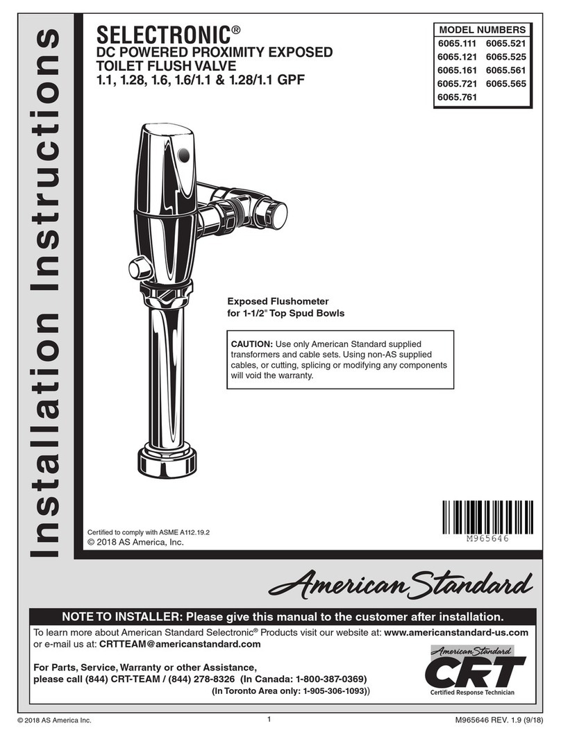
American Standard SELECTRONIC 6065.521 User manual
American Standard
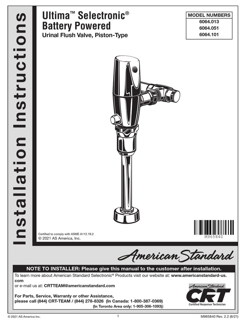
American Standard Ultima Selectronic 6064.013 User manual

American Standard
American Standard R127 User manual
American Standard
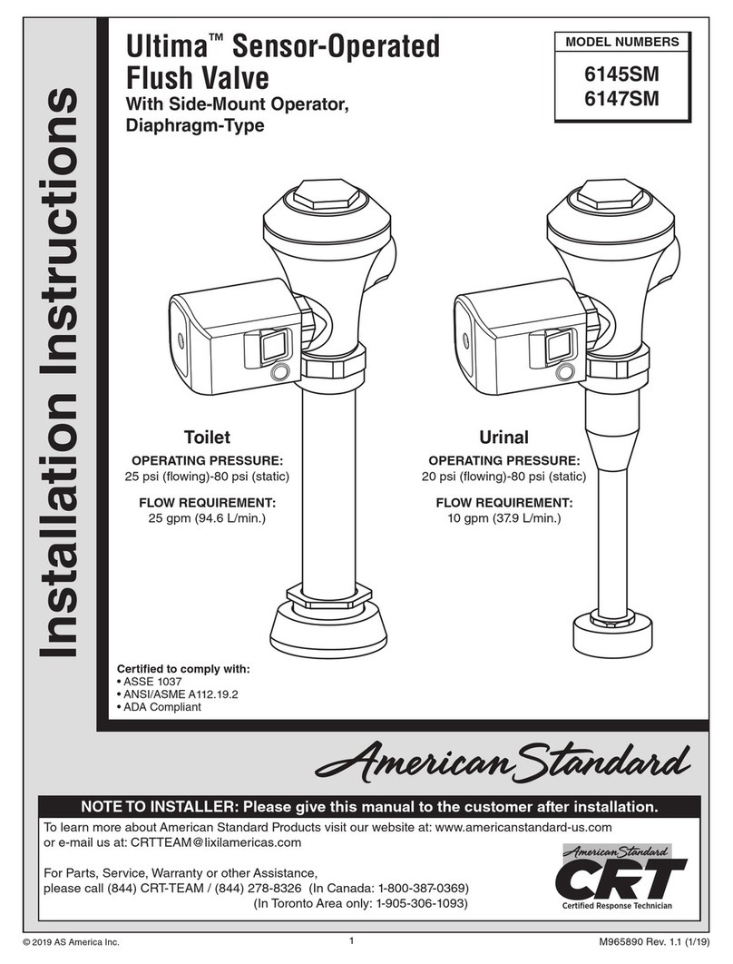
American Standard Ultima 6145SM User manual
American Standard
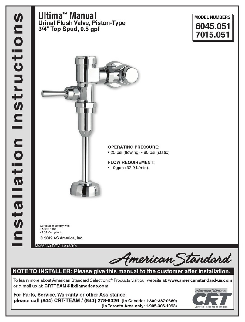
American Standard Ultima 6045.051 User manual
American Standard
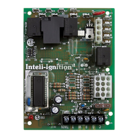
American Standard 50A65-475 User manual
Popular Control Unit manuals by other brands

Festo
Festo Compact Performance CP-FB6-E Brief description

Elo TouchSystems
Elo TouchSystems DMS-SA19P-EXTME Quick installation guide

JS Automation
JS Automation MPC3034A user manual

JAUDT
JAUDT SW GII 6406 Series Translation of the original operating instructions

Spektrum
Spektrum Air Module System manual

BOC Edwards
BOC Edwards Q Series instruction manual

KHADAS
KHADAS BT Magic quick start

Etherma
Etherma eNEXHO-IL Assembly and operating instructions

PMFoundations
PMFoundations Attenuverter Assembly guide

GEA
GEA VARIVENT Operating instruction

Walther Systemtechnik
Walther Systemtechnik VMS-05 Assembly instructions

Altronix
Altronix LINQ8PD Installation and programming manual

