Preferred TG-EL-D4B Series User manual

Instruction Manual SDI-TG-EL-D4B-xx-x-0 page 1 of 38 Revised 3/8/22
Preferred Utilities Manufacturing Corporation Firmware 1.06
FUEL SENTRY TANK GAUGE AND
LEAK DETECTION SYSTEM
Model TG-EL-D4B-xx-0-0
The TG-EL-D4B Tank Gauge/Fuel Management System with
Leak Detection System monitors one or two tanks. The D4B
tracks fuel deliveries and daily/weekly fuel consumption. It is a
powerful accounting tool. The leak-detection system is designed for
use with double wall tanks, vaulted tanks, single wall tanks with spill
basins, and double wall piping. The TG-EL-D4B is designed for use
with all fuel oils (No. 2 – No. 6), diesel, kerosene, jet fuel, and most
other petroleum products.
Features include:
Easy-to-read bar-graph touchscreen display
Printer option with automatic report printing
Automatic delivery report and data logging
Daily/weekly usage report and data logging
Daily HD-A2-C automatic leak sensor testing
Overfill alarm
Idle tank theft alarm
Eight Intrinsically Safe (I.S.) sensor inputs
RS485 and Ethernet Modbus
Fully field-configurable
D4B_Edit PC based configuration via USB
4-20 mA Xmtrs or switch sensors:
TG-EL-WF-x-C 4-20 mA wire float level sensor
TG-EL-HLT-x-C 4-20 mA head level sensor
Most other 4-20 mA level, head, bubbler, ultrasonic, or
magnetostrictive level sensors
HD-A2-C 4-20 mA discriminating leak sensor
RBS or PS-LDS float leak switch
Most other contact closure leak sensors
Table of Contents
SAFETY .................................................................................... 2
Specifications ............................................................................ 3
Ordering Information ................................................................. 3
Features .................................................................................... 4
Alarms & Status’s: ..................................................................... 5
Printer:....................................................................................... 6
Operation .................................................................................. 7
Menu Layout ............................................................................. 9
I/O Configuration Worksheet ................................................... 11
Physical Installation................................................................. 14
Wiring ...................................................................................... 15
Level Sensor Type Setup & "Stick Depth".............................. 20
Tank Dimensions and Stick Chart Types ................................ 22
Delivery Detection Setup ......................................................... 24
Theft Alarm Setup ................................................................... 25
Alarms and Status Functions Setup ........................................ 25
Printer ...................................................................................... 26
Troubleshooting & VIEW I/O ................................................. 26
Password ................................................................................ 28
Modbus ................................................................................... 29
Configuration Record .............................................................. 30
Panel Cutout Template ........................................................... 38

Instruction Manual SDI-TG-EL-D4B-xx-x-0 page 2 of 38 Revised 3/8/22
Preferred Utilities Manufacturing Corporation Firmware 1.06
SAFETY
WARNING
This product is intended for use in Commercial and Industrial installations,
it is NOT intended for Residential use.
This product is intended to be used by Trained Operators.
Installation, start-up, and troubleshooting is intended to be done by
Experienced Technicians familiar with Industrial Safety Codes
and installing devices in Hazardous Locations.
DANGER
Failure to comply with Control drawing 190789, and the instruction manuals of all Intrinsically
Safe sensors connected to the TG-EL-D4B, voids the Intrinsically Safe design and creates an
explosion risk in the hazardous area.
NOTE:
Do NOT begin to install or wire the TG-EL-D4B or the sensors unless the
TG-EL-D4B I/O Channel Configuration Worksheet has been completed and
all of the Intrinsic Safety wiring and physical installation notes have been read.
DANGER
Electric Shock Hazard
Multiple power sources may be present.
Disconnect all electric power sources, local and remote, before servicing

Instruction Manual SDI-TG-EL-D4B-xx-x-0 page 3 of 38 Revised 3/8/22
Preferred Utilities Manufacturing Corporation Firmware 1.06
Specifications
Inputs (15 total)
Analog: (8) 4-20 mA or contact closure
Each channel field-configured
Intrinsically Safe: Class 1, Zone 0, Group CD
Voc = 29.9, Isc= 99.5mA, Po= 0.75W
Resolution: 0.007%
Accuracy: 0.1%
Discrete: (2) 120 VAC, 13 mA
(5) 24 VDC, sinking, internal pull-up
Outputs (14 total)
Analog: (2) 4-20mA, 16 bit
650 ohms max, volume or depth
Relays: (4) SPST NO, 1.5A pilot, 120Vac
(2) SPDT, 10A 250Vac
Discrete: (6) 24 Vdc, 200mA, Sinking
Requires external power supply
Instrument
Input power: 120 VAC +/-15%, 50/60 Hz, 26 VA
Enclosure: Nema 12 Faceplate
Bezel: 3 7/8 w x 8 h x 1 d
Rear Case: 3 1/2 w x 7 9/16 h x 4 7/8 d
Panel Cutout: 3.61 w x 7.65 h
Ambient temp.: 32° to 131° F (0-55° C)
Display: Color Touch Screen
Communications
RS485: Modbus RTU, 4800-57600 baud
Ethernet: Modbus TCP
USB: for D4B_Edit config. Read/Write
Printer
Input power: 120 VAC +/-15%, 50/60 Hz, 20 VA
Size: 4.6"H x 4"W x 2.8"D
Enclosure: Nema 1
Ambient temp.: 32° to 122° F
Paper: 2.25" W, thermal, 30 columns
Ordering Information
Tank gauge
TG
-
EL
-
D4B
-
___
-
___
-
0
No enclosure, no printer 00
Wall-mount enclosure, no printer E0
Wall-mount enclosure, with printer EP
RS485 Modbus
0
Magnetostrictive Level Sensor…………..…………TG-EL-MSxx
Single Float, (1) 4-20mA
Magnetostrictive Level Sensor……………..TG-EL-MSxx-D420
Dual Floats, Fluid and Water levels, (2) 4-20mA
Wire float level sensor, 4-20 mA
(See TG-EL-WF for dimensional information.)
7-ft. max. depth ............................................. TG-EL-WF-7-C
12-ft. max. depth ........................................... TG-EL-WF-12-C
Submersible head level sensor, 4-20 mA
7-ft. max. depth, #2 oil and diesel ................ TG-EL-HLT-7-C
15-ft. max. depth, #2 oil and diesel .............. TG-EL-HLT-15-C
Leak sensor, dry/water/oil, 4-20mA
25-ft. sensor .......................................................... HD-A2-C
8-ft. sensor ......................................................... HD-A2-C-8
Sensor guard for HD-A2-C for sumps, vault floors,
bright areas ................................................................... HD-HSG
Leak sensor, float actuated, day tank, double wall pipe ...... RBS
Leak sensor, pump set leak float switch ........................ PS-LDS
Two-wire direct burial cable .............................................. 92612
(For use with TG-EL-WF-x-C, RBS, HLS.)
Four-wire vented direct burial cable .................................. 26000
(For use with TG-EL-HLT-x-C.)
Fil-A-Larm Station (120 V)………………A-AV-xD3-SS
Printer for panel mounting ....................... TG-EL-D4x-PRINTER
(Shipped loose for TG-EL-D4B-00-x-0 or TG-EL-D4B-E0-x-0.)
Windows configuration software (not equired)………..D4B_Edit

Instruction Manual SDI-TG-EL-D4B-xx-x-0 page 4 of 38 Revised 3/8/22
Preferred Utilities Manufacturing Corporation Firmware 1.06
Features
The TG-EL-D4B can monitor tank volume (gallons or liters) and tank leak detectors for one or two tanks via
8 Intrinsically Safe inputs.
Fully field-configurable: The TG-EL-D4B can be completely configured in the field from its touchscreen menus.
A laptop with D4B_Edit software can also be used to configure the D4B via the USB port.
Gallons (or liters) volume calculation based on:
a) One of five standard tank shapes with user-entered tank dimensions (inches or centimeters), or
b) A user-entered volume-vs.-depth stick chart (up to 51 points), typically from tank mfg. stick chart data.
The D4B can print a stick chart for either dimension-based or manual stick chart-based calculations.
Delivery detection and Data Logging: The TG-EL-D4B automatically detects a delivery and stores the delivered volume in a
time/date-stamped data-logger nonvolatile memory. The most recent 50 Deliveries are saved.
The printer can be configured to automatically print a time/date-stamped “Volume Delivered” report after each delivery that can be used
to verify the invoice before payment. The complete delivery history can also be viewed from the TG-EL-D4B screen, or read via USB into
D4B_Edit.
Usage monitoring and Data Logging: Every day at midnight, the TG-EL-D4B computes the usage for the previous day based on: tank
volume at the previous midnight, the sum of all deliveries during the day, and the tank volume at the current midnight. Usage less than
(0.1% of Full Tank volume) or (Idle Tank Volume Change Theft SP) is considered to be 0 usage for the day. This prevents nuisance
usage due to fluid thermal expansion/contraction.
The resulting daily usage is date-stamped and stored in the data-logger nonvolatile memory. Every Sunday at midnight, the previous
seven days are added together and stored as the weekly usage. The oldest data are overwritten by newer data. Usage data can be
printed, viewed via the touchscreen menus, or read by Modbus.
For a single-tank system, the D4B stores the last 70 days and the last 52 weeks usage for the tank.
For a dual-tank system, the D4B stores 70 total usage records, so typically 35 days and 26 weeks for each tank.
On Demand HD-A2-C Leak Detector Test: The user, or an inspector, can initiate an HD-A2-C test from the display menu. If the printer
option is installed a time/date stamped pass/fail report will be printed.
Daily Automatic HD-A2-C Leak Detector Testing and Data Logging: Every Day at midnight, all HD-A2-C Leak Detectors are
automatically tested. If any Fail, the Manual Reset Leak Alarm is activated. The last 70 pass/fail results for each HD-A2-C, and the
channel(s) that failed is stored in the data logger.
Flexible, multipurpose Intrinsically Safe (I.S.) inputs: Each of the eight I.S. input channels can be connected to either a two-wire 4-20
mA transmitter or a contact closure. A wide variety of ullage, depth, head, discriminating leak, leak switch, fill alarm level switch, fill alarm
silence PB switches and sensors can be field-configured from the TG-EL-D4B menus to be connected to any one of the eight I.S. input
channels.
Selection of a standard Preferred Utilities sensor also configures the 4-20mA engineering units. Other I.S. 4-20 mA transmitters can also
be used with manually entered 4-20mA engineering units.
RS485 and Ethernet Modbus: The current depths, volumes, alarms, and statuses can be read via Modbus. The previous day delivery
and usage data can be read via Modbus. See the table at the end of the manual for Modbus addresses.
Custom Names: The touchscreen allows the user to enter a 12 character Name for each of the 15 Inputs. Each Tank also has a user
entered Name. These Custom Names appear on all Operator screens, Alarms, and Alarm History screens.
However, the Configuration/Setup menus used during installation the TG-EL-D4B refer to “Tank A” and “Tank B”.

Instruction Manual SDI-TG-EL-D4B-xx-x-0 page 5 of 38 Revised 3/8/22
Preferred Utilities Manufacturing Corporation Firmware 1.06
Alarms & Status’s:
The TG-EL-D4B can be configured to generate a wide variety of alarms. Alarms are time and date-stamped and then stored in the
data-logger nonvolatile memory. The alarm history can be printed, viewed on the touchscreen, or read into D4B_Edit PC software. The
TG-EL-D4B stores the last 50 alarms and events.
Over Fill alarms (FILALM x and OFIL-LK C): Typically an outdoor bell and light (FA-AV-xD3, or equal) are installed near the tank fill
pipe to warn the driver to stop filling the tank before it overfills.
For each tank, any, or all, of these signals/sensors can affect the outdoor bell:
Level Sensor HI Volume Setpoint (HI SP) TG-EL-WF, TG-EL-HLT, or other 4-20mA level sensor
Level Sensor HIHI Volume Setpoint (HIHI SP) TG-EL-WF, TG-EL-HLT, or other 4-20mA level sensor
Tank high level float switch (FILALM LS) HLS, PLS, or other float switch
Vent Pipe float switch (VENT LS) RBS, or other float switch
Leak Sensor (LK HD-A2, LK CONTAC) HD-A2-C, RBS, HLS, PS-LDS, or other
The FILALM x output rings the outdoor bell when: HIHI SP is exceeded, or FILALM LS or VENT LS is active.
The OFIL-LK C output rings the outdoor bell when: HI SP or HIHI SP is exceeded, or FILALM LS, VENT LS, or any Leak Sensor
(HD-A2-C or LK CONTAC) is active for either tank.
The outdoor FilAlarm bell can be silenced by the driver if an outdoor pushbutton is wired to an FILALM AS input, or it will automatically
silence after 60 seconds (adj. 10-120 sec.). Before filling the tank, the driver can test the fill alarm by pressing and holding the outdoor
alarm silence button for more than five seconds.
The FilAlarm output (bell) will re-activate every time any of the related signals activates.
FILALM x output example: Volume > HIHI SP, bell sounds, bell silences (Driver or Auto Silence), tank keeps filling, FILALM LS tank level
switch activates, bell sounds, bell silences, tank keeps filling, VENT LS vent pipe switch activates, bell sounds. The OFIL-LK output
responds similarly, but for more sensors.
The Outdoor light is typically activated by the HIHI x ST output, which energizes if Volume > HIHI SP, FILALM LS, or VENT LS is active.
For dual-tank systems, individual (or common) lights, bells, alarm silence buttons and/or bells can be used, provided enough outputs are
available.
Overfill Alarms do not trigger the D4B local alarm beeper or ALARM COM output, and are not recorded in the Alarm History. However, HI
and HIHI Volume alarms are data logged.
Theft alarm: Thefts are monitored in two ways: idle tank volume change and high usage rate.
Idle tank: An idle tank will trigger a theft alarm if the volume drops an adjustable amount below the volume saved at the time the tank
became idle. This mode requires a contact closure input that indicates when the tank is idle. This could be a manual valve auxiliary
switch, a pump starter auxiliary switch, a flow switch, a diesel generator “not running” contact, or other means.
High usage: The D4B monitors the tank volume every few minutes and calculates a short-term usage rate. If this rate is higher than a
user-adjustable theft rate, a theft alarm will be triggered. This strategy assumes that the normal peak flow rate is known and that the theft
is caused by a high flow rate removal of oil by a pump.

Instruction Manual SDI-TG-EL-D4B-xx-x-0 page 6 of 38 Revised 3/8/22
Preferred Utilities Manufacturing Corporation Firmware 1.06
Other Alarm and status functions: In addition to the fill alarm, theft alarm, and leak alarms discussed above, each tank has four
volume-based alarm functions, four volume-based status functions, and two volume-based control functions.
Alarm and status functions are very similar. Status functions do not trigger the alarm outputs.
Almost all alarms reset/silence automatically when the condition clears. A Leak alarm will stay in alarm until the the Leak signal returns
to normal and is then Reset by the Operator. The Low-Low level alarm can be configured as either manual reset or auto reset. The
ALARM COM output can be silenced either from the faceplate Alarm Silence button, or from a COMMON AS input from an external
pushbutton.
There are four user-adjustable volume setpoints for each Tank (total of eight), and one alarm delay seconds parameter:
HIGH-HIGH, HIGH, LOW, LOW-LOW
Each setpoint is used by both an alarm function and a status function, and sometimes by other functions.
The setpoint name describes the logic, examples:
HIGH-HIGH setpoint: If the volume is higher than the HIGH-HIGH setpoint for more than the alarm delay seconds, outputs configured as
either HIHI x AL or HIHI x ST are triggered.
LOW setpoint: If the volume is lower than the LOW setpoint, LO x AL and LO x ST outputs are triggered.
Other setpoint uses:
The HIGH-HIGH setpoint triggers the Fill Alarm function described above.
FILL function: If volume < LOW setpoint, FILL turns ON. If volume > HIGH setpoint, FILL turns OFF.
If both conditions are true, FILL turns OFF.
DRAIN function: If volume > HIGH setpoint, DRAIN turns ON. If volume < LOW setpoint, DRAIN turns OFF.
If both conditions are true, DRAIN turns ON.
Any Alarm or Status can energize any output. The user configures each output to respond to the desired Alarm or Status. Multiple
outputs can be configured to respond to the same Alarm or Status. See the ROUT/DOUT CONFIG menu.
Printer:
The TG-EL-D4B-EP-0-0 includes a printer and is pre-mounted in a wall mount enclosure.
The TG-EL-00-0-0 and TG-EL-E0-0-0 does not include a printer. The TG-EL-D4A-PRINTER can be purchased separately, mounted in a
user provided enclosure.
The following printed reports are provided:
Short report includes for each tank: current depth and volume; previous day’s usage; last delivery and the
most recent HD-A2 test result; and the last 10 alarms.
Long report includes everything on the short report, plus: the 10 latest deliveries for each tank, the last 8 daily consumptions for
each tank, and the last 5 weekly consumptions for each tank.
Stick Chart report shows the volume at various depth intervals, one tank per report (maximum of 50 evenly spaced depths, plus the
full volume and depth).
Any of the above reports can be printed at any time by the operator via the touchscreen PRINT button if the printer option is enabled.
In addition, reports can be configured to automatically print based on the following events:
Every Midnight: Disable, Short Report, Long Report
Every Sunday Midnight: Disable, Long Report
After Any Alarm: Disable, Short Report
After a Delivery: Disable, Long Report
If the printer is not installed, all data logged data can also be extracted with the D4B_Edit Windows PC App for viewing and saved in a
.csv format for easy integration into a spreadsheet.

Instruction Manual SDI-TG-EL-D4B-xx-x-0 page 7 of 38 Revised 3/8/22
Preferred Utilities Manufacturing Corporation Firmware 1.06
Operation
The main screen displays the tank volume and fluid depth
(gallons and inches, or liters and centimeters). With volume being
displayed above the depth measurement.
There are three Home screens: Tank A only, Tank B only, Tank A & B.
If the TG-EL-D4B is configured to monitor 2 tanks, press the right or left
arrow button to change main screens.
Tick marks on right hand side of the bargraph indicate level alarm
setpoints.
If a dual float level xmtr is installed the water depth in the bottom of the tank
is displayed to the left of the bargraph.
When an alarm occurs, the bargraph(s) will blink, and the Silence button
will blink. Depending on how the D4B is configured in the field, an alarm
can cause an external alarm bell or horn to activate.
Press the Silence button to stop the blinking and silence the external
bell/horn.
After Silencing, if any Alarms are still active, the Alarms button appears.
Press the Alarms button to display the Active Alarms screen.
The Reset button appears if any alarms require a Manual Reset. Reset will
only reset an alarm if if has Cleared (ie returned to normal).
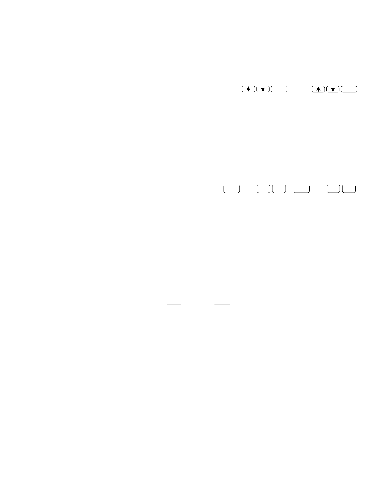
Press History to display the History screen.
The History screen displays the Time/Date of the most recent 50 Alarms
and Events.
Touch the Up or Down arrow to advance to the next page of History. Touch
Date to enter a time/date in order to jump to the nearest History record.
The Hide Events and Show Events removes or displays Events.
The History memory is retained when powered down. The History can be
extracted via the USB port using the free D4B_Edit Windows App.
Reset
Silence Menu
History
Alarms
Home
Tank 2 High High Alarm
4608 Gallons ALARM 02:23:59
12/15
Tank 2 High Alarm
3991 Gallons ALARM 02:23:48
12/15
Tank 1 Low Low Alarm
2431 Gallons RESET REQ’d 02:22:57
12/15
Tank 1 Low Alarm
2860 Gallons ALARM 02:22:36
12/15
CH2 Leak Alarm
RESET REQ’d 02:19:06
12/15
Active Alarms
CH2 Leak Alarm
CLEAR 02:45:51
12/15
CH2 Leak Alarm
ALARM 02:45:51
12/15
CH2 Leak Alarm
CLEAR 02:45:46
12/15
Tank 1 Low Low Alarm
3683 Gallons CLEAR 02:41:26
12/15
Tank 2 High Alarm
4293 Gallons CLEAR 02:41:25
12/15
Tank 2 High High Alarm
4609 Gallons CLEAR 02:41:21
12/15
SILENCE
History Date
BackAlarms Home
Hide
Events
Show
Events
SILENCE MENU
Tank 1 Delivery In Progress
0.0
Full:
8000.0
Tank 1 Volume IN-GALLON
5615
HISTORY
ALARMS
49.7
0.0
Tank 2 Volume IN-GALLON
4121
36.5
Full:
8000.0
Water
3.6
Water
1.4
SILENCE MENU
Tank 1 Delivery In Progress
0.0
Full:
8000.0
Tank 1 Volume IN-GALLON
5615
HISTORY
ALARMS
49.7
Water
3.6
Instruction Manual SDI-TG-EL-D4B-xx-x-0 page 8 of 38 Revised 3/8/22
Preferred Utilities Manufacturing Corporation Firmware 1.06
History, HD-A2 leak test, and setting the clock:
The main menu is used to display these features.
See the complete menu layout in the next section for other features and information.
Menu operation:
From the operator home screens, press MENU.
This will bring up the Main Menu options.
History: Daily usage, weekly usage, deliveries, and alarms
From the main screen:
Press MENU.
TANK MAIN MENU appears.
Press Usage/Deliv. History
HISTORY submenu appears.
Daily Usage, Weekly Usage, and Delivery Histories can be selected.
A specific datsa can be entered and searched in any of the history screens.
Power outages can affect usage data:
Daily and weekly usage data are calculated at midnight. Power outage
scenarios include:
After power is restored: Usage is calculated from when power came back
ON until the next midnight.
Power off at midnight: Usage is not calculated, and 0 is recorded in all
“missed” days upon power up.
Power off Sunday midnight: Weekly usage is not calculated.
TEST HD-A2 (leak sensors):
The TG-EL-D4B tests all installed HD-A2 leak sensors that are not in alarm every midnight. Selecting the TEST HD-A2s item in the main
menu starts an HD-A2 test sequence and allows the user to witness the test.
Setting the clock time and date:
If the power is off for more than 10 days, or when the Daylight Saving Time shift occurs, the user will have to manually adjust the time,
date, and day of week for the clock.
From the main menu, select Utilities > Set Clock. Time is set in 24-hour format.
Use the Utilites Menu to access the touch calibration and cleaning screens, as well as the screen settings.
CAUTION: Changing the date can cause the data-logger usage memory to be erased in some circumstances. It will not affect any of the
TG-EL-D4B configuration parameters.
Password:
The TG-EL-D4B has an optional password system. Passwords are disabled when the TG-EL-D4B is shipped. To enable a password
press “Change Tech Password” on the Password Menu Screen. This allows the user to enter the desired password. Valid passwords are
numeric only and can be anything between -32768 to +32768. Once a password is set, the user must be logged in to change the
password again. Setting the password to 9999 disables the password system on the controller.
When the password system is activated and the D4B is logged out:
Reports can be printed.
The main display tank can be selected.
Alarms can be silenced.
All submenus and menu items can be displayed.
The clock can be set.
An HD-A2 test can be started.
No other items can be changed within the menu system.
When a password is entered, it automatically logs out after one hour.
Daily Usage History
Tank 2
12/22 1218
Tank 1
12/22 2725
Tank 2
12/21 471
Tank 1
12/21 757
Tank 2
12/20 0
Tank 1
12/20 0
SILENCE
Date
BackAlarms Home
Delivery History
Tank 1
1/26 08:17:07 1306
Tank 2
1/23 13:22:13 2803
Tank 1
1/23 13:22:45 1311
Tank 1
1/14 17:39:16 5109
Tank 1
12/30 17:38:02 1985
Tank 2
12/23 00:15:19 1604
SILENCE
Date
BackAlarms Home

Instruction Manual SDI-TG-EL-D4B-xx-x-0 page 9 of 38 Revised 3/8/22
Preferred Utilities Manufacturing Corporation Firmware 1.06
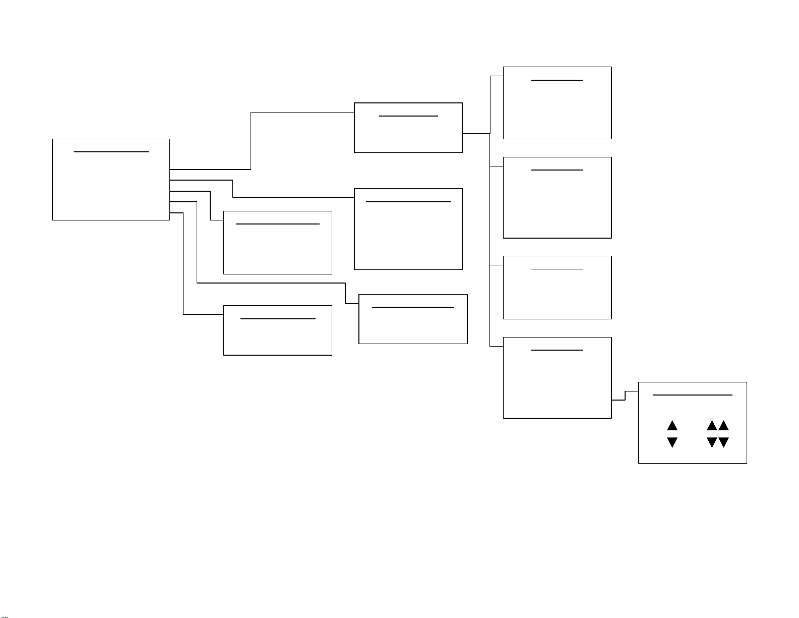
Menu Layout
Main Menu
Usage/Deliv. History
Test HDA2's
Utilities
Password
Configure/Setup
Communication Setup
View I/O
Ch. x AOUT
Function
Ch. x ROUT/DOUT
Function
Ch. x DIN
DIN CH Tank Select
DIN Name
DIN Sensor Type
NO / NC
Ch. x I.S. AIN
AIN CH Tank Select
AIN Name
AIN Sensor Type
Input at 4 mA
Input at 20mA
Depth Adjust
NO / NC
Configure I/O
Ch. 1-8 I.S. AIN
Ch. 9-15 DIN
Ch. 1-12 ROUT/DOUT
Ch. 1-2 AOUT
Alarm Delays
Alarm Delay Seconds
FillAlarm Auto Silence
Printer
Printer Option
Print at Midnight
Print After Delivery
Print After Alarm
Print Sunday Week Rpt
Communication Setup
Modbus RTU RS485
Modbus TCP Ethernet
Utilities
Set Clock
Calibrate Touch
Clean Screen
Screen Settings
Firmware Version
Startup History
Pasword
Enter
Change
Logout
Screen Settings
Brightness
Touch Buzzer
Alarm Buzzer
Tank A & B Configuration
Menus on Next Page
Configure/Setup
System Setup
Inputs/Outputs
Tank A
Tank B
Alarm Time Delays
Printer
System Setup
Unit Name
Location Name
Number of Tanks
Tank Units
Usage/Delivery History
Daily Usage
Weekly Usage
Deliveries
View I/O
Discrete I/O
Analog I/O
Instruction Manual SDI-TG-EL-D4B-xx-x-0 page 10 of 38 Revised 3/8/22
Preferred Utilities Manufacturing Corporation Firmware 1.06
Configure Tank A
Tank Name
Tank Shape and Size
High Alarms
Low Alarms
Theft Alarm
Deliveries Tank A Low Alarms
Low-Low Setpoint
Low-Low Mode
Low Setpoint
Low Enable
Tank A Theft Alarm
Theft Alarm Enable
Idle Volume Change SP
gpm / lpm Theft SP
Flat Horiz or
Dished End
H Obround or
V Obround
LinVert
Manual
Stick Chart
Tank A Stick Chart
Full Depth
Full Volume
Depth
Gallons
Tank A Data
Full Depth
Full Volume
Specific Gravity
Striker Plate Thickness
Tank A Data
Obround Width
Overall Length
Obround Height
Specific Gravity
Parallel Tank Qty
Striker Plate Thickness
Tank A Data
Tank Diameter
Overall Length
Straight Length
Specific Gravity
Striker Plate Thickness
Tank A Data
Full Depth
Full Volume
Specific Gravity
Depth Interval
Edit Stick Chart
Striker Plate Thickness
Tank A High Alarms
High-High Setpoint
High-High Enable
High Setpoint
High Enable
High Water Setpoint
High Water Enable
Tank A Deliveries
Tank A Delivery-Usage
Tank A Delivery Start Vol
Tank A Settling Seconds
Tank A Sizing
Stick Chart Type
Tank Data
Computed Full Volume

Instruction Manual SDI-TG-EL-D4B-xx-x-0 page 11 of 38 Revised 3/8/22
Preferred Utilities Manufacturing Corporation Firmware 1.06
I/O Configuration Worksheet
For each input channel, the user must enter: sensor name, sensor type, the tank the sensor is associated with, the sensor option, and possibly the sensor calibration data. Functions must
be assigned to the 4-20 outputs and the output outputs. Read all feature descriptions before completing.
The table and notes below detail the allowable configuration settings and the restrictions for each sensor type.
Allowable INPUT CONFIG settings for each SENSOR TYPE:
SENSOR TYPE
Description
Allowed
qty. per
tank
Allowed
tanks
Allowed
INPUT
CHANNELS
Contact NO / NC
Default
20 mA Cal.
Default
4 mA Cal.
LVL WF7
Level sensor, 7 ft., TG
-
EL
-
WF
-
7
-
C
note 1
A
,
B
IS AIN
1
-
8
84.0 ullage
0.0
LVL WF12
Level sensor, 12 ft., TG
-
EL
-
WF
-
12
-
C
note 1
A,B
IS AIN 1
-
8
144.0 ullage
0.0
LVL UL18
Level sensor, 18 ft, TG
-
EL
-
ULT
-
18
-
C
note 1
A,B
IS AIN 1
-
8
216.0 ullage
0.0
LVL OTHER
Level sensor, other 4
-
20 mA
note 1
A,B
IS AIN 1
-
8
100.0 depth
0.0
HEAD HL7
Head level sensor, 7 ft.,TG
-
EL
-
HLT
-
7
-
C
note 1
A,B
IS AIN 1
-
8
80.0" of water
n/a
HEAD HL15
Head level sensor, 15 ft.,TG
-
EL
-
HLT
-
15
-
C
note 1
A,B
IS AIN 1
-
8
160.0" of water
n/a
HEADOTHER
Head level sensor, other 4
-
20 mA
note 1
A,B
IS AIN 1
-
8
100.0" of water
n/a
LK HD
-
A2
Leak sensor, HD
-
A2
-
C, dry/oil/water discriminating
6
A,B,C
IS
AIN 1
-
8
n/a
n/a
LK CONTAC
Leak sensor, switch contact
6
A,B,C
IS AIN 1
-
8
N.C. or N.O.
n/a
n/a
FILALM LS
Tank Overfill alarm high
-
high level switch
1
A,B
IS AIN 1
-
8
N.C. or N.O.
n/a
n/a
VENT LS
Vent Pipe Overfill alarm high
-
high level switch
1
A,B
IS AIN 1
-
8
N.C. or N.O.
n/a
n/a
FILALM AS
Fill alarm remote alarm silence
1
A,B,C
IS AIN 1
-
8
N.C. or N.O.
n/a
n/a
FILALM AS
Fill alarm remote alarm silence
1, note 1
A,B,C
xx DIN 1
-
5
N.C. or N.O.
n/a
n/a
IDLE TANK
Idle tank theft alarm enable
1
A,B
xx DIN 1
-
5
N.C. or N.O.
n/a
n/a
COMMON AS
Common alarm, alarm silence contact
note 1
C
xx DIN 1
-
5
N.C. or N.O.
n/a
n/a
Notes: 1) Allowed qty. per tank:
FILALM AS: Either one per tank or one common, but not all three.
COMMON AS: Only one per system.
2) Allowed tanks: A = Tank A; B = Tank B; C = common area or piping (not related to a specific tank).
3) Contact input SENSOR OPTION:
N.C.: Normally closed contact. Contact opens when sensor activates.
N.O.: Normally open contact. Contact closes when sensor activates.

Instruction Manual SDI-TG-EL-D4B-xx-x-0 page 12 of 38 Revised 3/8/22
Preferred Utilities Manufacturing Corporation Firmware 1.06
TG-EL-D4B I/O Configuration Worksheet (continued)
Intrinsically Safe Analog Inputs (IS AIN)
Discrete (On/Off) Inputs (AC DIN and DC DIN)

Instruction Manual SDI-TG-EL-D4B-xx-x-0 page 13 of 38 Revised 3/8/22
Preferred Utilities Manufacturing Corporation Firmware 1.06
TG-EL-D4B I/O Channel Configuration Worksheet (continued)
4-20 mA Outputs AOUT Configuration: 4-20 mA Output Functions: X = A or B (Tank A or Tank B)
DISABLED Not used
TX VOL Tank X volume 20 mA = full volume
TX LVL Tank X level (fluid depth) 20 mA = tank diameter/full height/full depth
Relay Outputs ROUT Configuration: Relay and Discrete Output Functions: or Common to Both Tanks)
Discrete Outputs DOUT Configuration:
Ch. NO C NC Function
1123
2456
39 13
410 13
511 13
612 13
Terminals
Name:
Tank
Description:
Reset:
ALARM COM
Common alarm, with alarm local or remote alarm silence
Auto
LEAK COM
Combined Tank A or B or common
-
area leak alarm
Manual
LEAK
X
A,B
Tank
X
leak alarm
Manual
LEAK OTHR
Common
-
area leak alarm
Manual
FILLALM
X
A,B,C
OverFill alarm, Tank
X
(HIHI SP or FILALM LS or VENT LS
Auto
THEFT
X
A,B
Tank
X
theft alarm
Manual
HIHI
X
AL
A,B
Tank
X
high
-
high
-
volume alarm
Auto
HI
X
AL
A,B
Tank
X
high
-
volume alarm
Auto
LO
X
AL
A,B,C
Tank
X
low
-
volume alarm
Auto
LOLO
X
AL
A,B,C
Tank
X
low
-
low
-
volume alarm
Auto or
Manual
HIHI
X
ST
A,B
Tank
X
high
-
high
-
volume status.
Auto
HI
X
ST
A,B
Tank
X
high
-
volume status.
Auto
LO
X
ST
A,B
Tank
X
low
-
volume status
Auto
LOLO
X
ST
A,B
Tank
X
low
-
low
-
volume status
Auto
FILL X A,B Tank X fill valve/pump
Activates when volume drops below "Low" setpoint
Deactivates when volume rises above "High" setpoint
Auto
DRAIN
X
A,B
Tank
X
drain valve/pump
Activates when volume rises above "High" setpoint
Deactivates when volume drops below "Low" setpoint
Auto
OFIL
-
LK C
C
Combined FILLALM or HI SP or any Leak Alarm
Auto
Ch. +
-Function
140
39
242
41
Terminals
Instruction Manual SDI-TG-EL-D4B-xx-x-0 page 14 of 38 Revised 3/8/22
Preferred Utilities Manufacturing Corporation Firmware 1.06
Physical Installation
WARNING
Failure to comply with Control drawing 190789, and the instruction
manuals of all Intrinsically Safe sensors connected to the TG-EL-D4B,
voids the Intrinsically Safe design and creates an explosion risk in
the hazardous area.
TG-EL-D4B-00-x-x is designed for flush mounting in an enclosure.
TG-EL-D4B-Ex-x-x is pre-mounted in an enclosure.
The TG-EL-D4B should be mounted in a non-hazardous, indoor, NEMA 12
location that is free from excessive vibration. It is rated for continuous operation
over the 32º F-122º F (0º C-50º C) range.
The optional printer is rated NEMA 1 and should not be exposed to mists or
sprays.
Read all of the Intrinsic Safety (I.S.) requirements on drawing 190789 and in the
Wiring section before mounting the TG-EL-D4B.
The Intrinsically Safe wiring must remain physically separated from all other
non-Intrinsically Safe wiring by means of conduit, raceways, partitions, or tie-downs.
Tie-downs are acceptable if a 2" minimum separation is permanently maintained.
The I.S.-vs.-non-I.S. separation must be maintained both inside the panel that the
TG-EL-D4B is mounted in and outside the panel, all the way to the tank sensors.
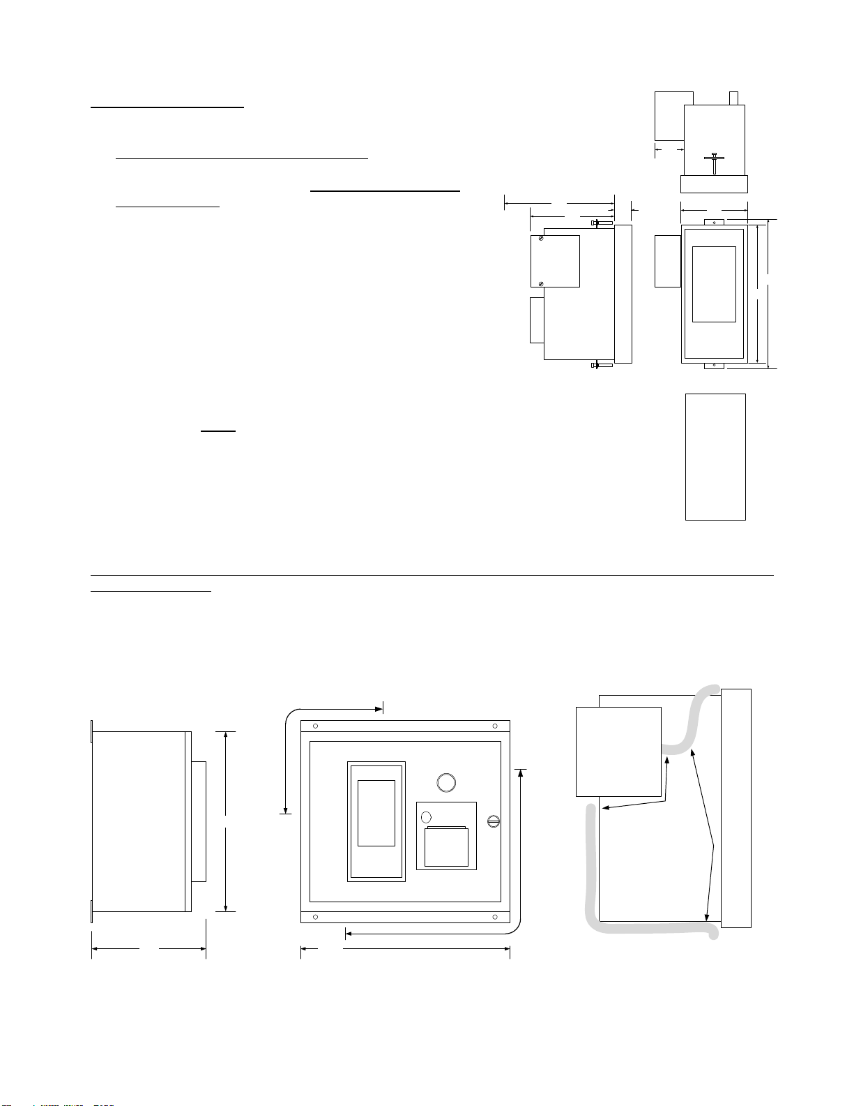
See the sketches below for conduit entry locations and internal wire routing paths that will maintain the 2" minimum separation between
I.S. and Non-I.S. wiring.
TG-EL-D4B-EP-x-x Dimensions
Conduit Entry
Internal Field Wiring
Locations Routing
3.88
8.00
Touch
Screen 8.74
1.70
Plug-in Terminals
Removable Cover
for
Intrinsically Safe
Terminals
1.00
4.88
6.38
Clearance If an Ethernet Cable is used
Panel Cutout
3.61 x 7.62
Non-Intrinsically Safe
Wiring Routing
Intrinsically Safe (I.S.)
Wiring Routing
Removable
Cover for
Intrinsically Safe
Terminals
Maintain at least 2"
separation between all
I.S and all non-I.S. wiring.
Use tie-wraps, hold downs,
or wiring duct to prevent
movement of wires.
Touch
Screen
Intrinsically Safe
Conduit Locations
Non - Intrinsically Safe
Conduit Locations
14.00
12.00
7.65

Instruction Manual SDI-TG-EL-D4B-xx-x-0 page 15 of 38 Revised 3/8/22
Preferred Utilities Manufacturing Corporation Firmware 1.06
Wiring
NOTE:
Do NOT begin to wire the TG-EL-D4B or the sensors unless the
TG-EL-D4B I/O Channel Configuration Worksheet has been completed and
all of the Intrinsic Safety wiring and physical installation notes have been read.
WARNING
Failure to comply with Control drawing 190789, and the instruction manuals of all Intrinsically
Safe sensors connected to the TG-EL-D4B, voids the Intrinsically Safe design and creates an
explosion risk in the hazardous area.
Intrinsically Safe wiring notes:
What is “Intrinsic Safety”? "Intrinsically Safe" (I.S.) means that when the TG-EL-D4B-xx-x-x tank gauge and compatible sensors are
properly installed, the sensors and the field wiring in the hazardous area will be incapable of releasing sufficient energy to cause ignition
of a Group C or D hazardous atmosphere.
The installation must comply with the requirements of the TG-EL-D4B Control Drawing 190789 (next page) and all requirements on the
control drawings of all associated apparatus in the hazardous location that is wired to the TG-EL-D4B terminals 21, 22, 51 through 70.
The Intrinsically Safe wiring must remain physically separated from all other non-Intrinsically Safe wiring by means of conduit, raceways,
partitions, or tie-downs. Tie-downs are acceptable if a 2" minimum separation is permanently maintained.
The ground wires connected to terminals 21 and 22 are an essential part of the Intrinsic Safety design of the TG-EL-D4B. Two
separate, independent, I.S. ground wires must be run from terminals 21 and 22 back to the grounding point of the AC power-supply
system with less than a 1-ohm resistance. This wiring can NOT be electrically combined with any other AC ground wiring. Splices are not
recommended. Follow all NEC and CSA codes for installation and marking of Intrinsically Safe wiring and grounding.
The capacitance and inductance of the field wiring cable affects the Intrinsically Safe design as noted on Control Drawing 190789.
Preferred p/n 92612 and 26000 cables are rated at less than 0.00005 uF/ft. and 0.0002 mH/ft.
1000-ft. cable runs, or less, of either 92612 or 26000 cable satisfies drawing 190789 I.S. capacitance and inductance requirements when
wired from from any TG-EL-D4B-xx-x I.S. input channel to any of the following: TG-EL-WF-7-C, TG-EL-WF-12-C, TG-EL-HLT-7-C, TG-
EL-HLT-15-C, TG-EL-ULT-18-C, HD-A2-C, or any simple switch.
"Simple switches" are inherently Intrinsically Safe and do not require UL, FM, CSA, or other approvals to be used in a hazardous location
when connected to an Intrinsically Safe associated apparatus (the TG-EL-D4B).
A "simple switch" is a mechanically actuated electrical contact that does not have any other electrical components (especially no added
capacitance and no added inductance). A simple switch does not store or discharge any electrical energy. All electrical energy is
provided by, and limited by, the I.S. design of the
TG-EL-D4B.
Non-Intrinsically Safe wiring notes:
Do not run low-voltage DC wiring bundled with, or in the same conduit as, AC wiring.
Ground DC shielded cables only where shown.
Insulate exposed shields to prevent connections to ground.
WARNING
Connecting Non-Intrinsically Safe devices to any Intrinsically Safe terminal voids the Intrinsically Safe
design and creates an explosion risk in the hazardous area

Instruction Manual SDI-TG-EL-D4B-xx-x-0 page 16 of 38 Revised 3/8/22
Preferred Utilities Manufacturing Corporation Firmware 1.06
HAZARDOUS LOCATION NON-HAZARDOUS LOCATION
Class I, Div 1, Groups C or D
Class I, Zone 0, Groups IIA or IIB
Ex ia IIB T4
Vmax (or Ui ) > 29.9V
Imax (or Ii ) > 99.5mA
Pmax (or Pi ) > 0.75W
Ci + Ccable < 0.25 uF
Li + Lcable < 1.5mH
Uo or Voc = 29.9V
Io or Isc = 99.5mA
Po = 0.75W
Co or Ca = 0.25 uF
Lo or La = 1.5mH
Um = 250Vac/dc
Ta = 0 - 50C
INTRINSICALLY SAFE
APPARATUS
ENTITY PARAMETERS
TG-EL-D4B-xx-x-x
ASSOCIATED APPARATUS
ENTITY PARAMETERS
TG-EL-D4B-xx-x-x
INTRINSICALLY
SAFE
ASSOCIATED
APPARATUS
(see manual for
channels 3 thru 8)
P2 54
C2 56
IS G 22
Power
Source
Less Than
250 Vac
NOTES:
1. ‘Electric Code’ means: ANSI/NFPA 70 National Electrical Code, or Canadian Electrical Code, or Local installation Codes, as applicable.
2. Control equipment connected to the TG-EL-D4B-xx-x-x must not use or generate more than 250 Vac or Vdc with respect to earth.
3. The Capacitance and Inductance of the field wiring cable from the TG-EL-D4B to the Intrinsically Safe Apparatus must be calculated and
included in the calculations in Note 4. Ccable = Cable Capacitance for the installed length, Ci = Intrinsically Safe Apparatus Internal
Capacitance (marked on the device), Ca = TG-EL-D4B Max Allowed Connected Capacitance (see above). The same descriptions apply
for inductance: Lcabl e , Li , and La . If the cable capacitance and inductance per foot is not known, use: Ccable = 0.00006 uF/foot and
Lcable = 0.0002 mH/foot.
4. Third Party Listed, Entity Rated, Intrinsically Safe Apparatus can be connected to TG-EL-D4B terminals 51 - 70 IF it is suitable for the
application AND it is installed in accordance with the manufacturers instructions AND all wiring is in accordance with the
TG-EL-D4B-xx-x-x instructions AND it satisfies ALL of the following relationships:
Intrinsically Safe Apparatus Associated Apparatus (TG-EL-D4B-xx-x-x)
Vmax ( or Ui ) > Voc ( or Vt or Uo )
Imax ( or Ii ) > Isc ( or It or Io )
Pmax ( or Pi ) > Po
Ci + Ccable < Ca ( or Co )
Li + Lcable < La ( or Lo )
5. A Switch (with no added capacitance or inductance) is a Simple Apparatus and does not require Third Party Approval in order to be
connected to the TG-EL-D4B. See the Electric Code and ANSI/NFPA article 504.
6. The TG-EL-D4B-xx-x-x MUST be connected to a suitable ground electrode per the Electric Code. Resistance from the TG-EL-D4B-xx-x-x
Intrinsically Safe Ground terminals 21 and 22 to the AC Power Source Ground Electrode must be less than 1 ohm.
Two independent I.S. Ground wires (14 ga. Min.) must be run from the TG-EL-D4B to Ground (one to terminal 21, one to terminal 22).
7. Intrinsically Safe wiring from the TG-EL-D4B to the Intrinsically Safe Apparatus must remain physically separated from non-Intrinsically Safe
wiring by means of conduit, raceways, partitions, or tie-downs which permanently maintain at least 2" separation.
See the Electric Code and ANSI/NFPA article 504.
8. Multiple Intrinsically Safe circuits may be run in the same conduit or raceway IF the total insulation thickness separating conductors of
different circuits is at least 0.020" (0.50mm). See ANSI/NFPA 70 article 504.
9. Special Note for Model TG-EL-D4B-00-0-0:
The TG-EL-D4B-00-0-0 must be installed in an enclosure suitable for the application in accordance with the NEC.
10. WARNING: No User serviceable Parts. Return to factory for all repairs.
IS G 21
P1 53
C1 55
S 51
only 2 of 8
circuits are
shown.
Simple Switch. (No
added Capacitance
or Inductance)
2 wire
4-20mA
xmtr
+
-
Preferred Utilities
31-35 South St., Danbury, CT
TG-EL-D4B-xx-x-x
Intrinsically Safe Entity Parameters
Control Drawing
190789
DRAWN: PL 4/16/21
SCAL E: none
REV. DATE BY
PROPRIETARY INFO RMATION NOTICE
THIS DOCUMENT CONTAINS PROPRIETARY
INFORMATION OF PREFERRED UTILITIES AND IS
SUBMITTED IN CONFIDENCE SOLE Y FOR THE
PURPOSE OF USE BY THE SELLER/PURCHASER
IN CONSIDERING THE M ERITS OF THE
DOCUMENT. NO OTHER USE, DIRE CT OR
INDIRECT, OF THE DOCUMENT OR INFO RMATION
DERIVED THERFROM IS AUTHORIZED.
. . .
. . .
. . .
. . .
. . .
. . .
. . .
Note: This drawing is part of the Intrinsic Safety Design and Approval. Do not implement any changes without the approval of the Preferred Eng Mgr and the Approval Agency.
DESCRIPTI ON
.
.
.
.
.
.
.

Instruction Manual SDI-TG-EL-D4B-xx-x-0 page 17 of 38 Revised 3/8/22
Preferred Utilities Manufacturing Corporation Firmware 1.06
TG-EL-D4B-xx-x-0 Field Wiring Terminals
(This is NOT the physical terminal arrangement)
53
55
54
56
57
59
52
58
60
61
63
69
62
64
22
44
46
71
73
75
78
L1
N
Ch.1 +22Vdc Out
Ch.1 mA Input
Shield / Ground
I.S. Ground
Shield / Ground
Ch.2 +22Vdc Out
Ch.2 mA Input
Ch.3 +22Vdc Out
Ch.3 mA Input
Ch.4 +22Vdc Out
Ch.4 mA Input
Ch.5 +22Vdc Out
Ch.5 mA Input
Ch.6 +22Vdc Out
Ch.6 mA Input
120 Vac Supply
50/60 Hz, 26 VA
WARNING: Intrinsically Safe Wiring to I.S. Devices ONLY See I.S. Control Drawing 190789)
Terminals 21, 22 , 51-70
are under the I.S. cover
65
67
70
66
68
Shield / Ground
Ch.7 +22Vdc Out
Ch.7 mA Input
Ch.8 +22Vdc Out
Ch.8 mA Input
9
11
12
13
10
Ch. 3 ROUT
Ch. 4 ROUT
Ch. 5 ROUT
Ch. 6 ROUT
120 Vac, 1.5A, PILOT
1
2
3
4
5
6
Ch. 1 ROUT
Ch. 2 ROUT
120 Vac, 8 FLA, 1/2 HP
Ch. 9 24V DC DIN
7Ch. 14 120V AC DIN
8Ch. 15 120V AC DIN
Ch. 10 24V DC DIN
Ch. 11 24V DC DIN
Ch. 12 24V DC DIN
Ch. 13 24V DC DIN
24V DC
-
43 24V DC
-
WARNING
Failure to comply with Control
drawing 190789, and the instruction
manuals of all Intrinsically Safe
sensors connected to the TG-EL-D4B,
voids the Intrinsically Safe design and
creates an explosion risk in the
hazardous area.
40
39
42
41
Ch.1
4-20mA
Output
+
-
+
-
Ch.2
4-20mA
Output
48
50
77
79
81
83
Ethernet
86
DOUT DC -
80
82
Tx
Rx
84
DC-
Printer
RS232
45
47
A+
B-
49
Common
RS485
Modbus
Ch. 7 DOUT
Ch. 8 DOUT
Ch. 9 DOUT
Ch. 10 DOUT
Ch. 11 DOUT
Ch. 12 DOUT
I.S. Ground
21
51 Shield / Ground
86
DOUT DC +

Instruction Manual SDI-TG-EL-D4B-xx-x-0 page 18 of 38 Revised 3/8/22
Preferred Utilities Manufacturing Corporation Firmware 1.06
TG-EL-D4B-00-0-0
Field Wiring Terminal Block Arrangement (Rear View)
See the worksheets on pages 12 - 13 for I/O channel terminal numbers
74
76
78
80
82
84
86
72
73
75
77
79
81
83
85
71
USB (Main)
Ethernet
LED
1
2
3
4
(Aux) USB
Remote
I/O
LED 1
2
Fuse
3.15A
SLO-BLO
70
68
54
56
58
60
62
64
66
52
69
67
53
55
57
59
61
63
65
51
22
21 Intrinsic
Safety
Terminals
Cover
DC -
C8 -
C2 +
C2 -
C4 +
C4 -
C6 +
C6 -
C8 +
DC -
DC -
C7 -
C1 +
C1 -
C3 +
C3 -
C5 +
C5 -
C7 +
DC -
IS Gnd (DC -)
IS Gnd (DC -)
50
48
34
36
38
40
42
44
46
32
DO8
DO7
AO1+
AO2+
DI9
DI10
485C
485-
DC -
DC -
DC -
DC -
485+
49
47
33
35
37
39
41
43
45
31
DI15
DI14
R2 NC
R2 C
R2 NO
R1 NC
R1 C
R1 NO
L1
L1
N
N
8
7
6
5
4
3
2
1
13
12
11
10
9
R3-6 C
R6 NO
R5 NO
R4 NO
R3 NO
DC -
PR T
PR R
DC-
DO -
DI12
DI13
DO9
DO10
DO11
DO12
DO +
DI11
Terminal Number Notes:
L1, N, 7, 8 are 120Vac circuits
1-5, 9-13 are relay dry contacts.
Can be a mixture of 120Vac
and Low Voltage DC circuits
31-50, 71-86 are low voltage DC
circuits
21-22, 51-70 are Intrinsically Safe (IS)
circuits. IS wiring must be kept at
least 2" away from all other wiring

Instruction Manual SDI-TG-EL-D4B-xx-x-0 page 19 of 38 Revised 3/8/22
Preferred Utilities Manufacturing Corporation Firmware 1.06
The following partial schematics are included as an aid to troubleshooting.
AIN ch. 1-8: 4-20mA Xmtr Intrinsically Safe
Total Loop Ohms = Field Wiring Ohms + 442 Internal Ohms
53
55
51
392
50.0
ohms
+ 24 V
to A/D conv.
(20mA = 1.333V)
+
-
2 Wire
4-20mA
Xmtr
Inputs 1-8 Schematic Overview
( I.S. Barrier parts not shown)
22.5-27.5 mA
Limiter
AIN ch 1
terminals shown
AIN ch. 1-8: Contact Closure Sensor Intrinsically Safe
22.5-27.5 mA when
Contact is Closed
57
59
51
392
50.0
ohms
to A/D conv.
(20mA = 1.000V)
Inputs 1-8 Schematic Overview
( I.S. Barrier parts not shown)
22.5-27.5 mA
Limiter + 24 V
AIN ch 3
terminals shown
AC DIN ch. 14-15: Contact Closure Sensor Non-Intrinsically Safe
7
to CPU
+V
TG-EL-D4B “N”
AC DIN ch 14
terminals shown
TG-EL-D4B
120V “L1” 11 mA when
Contact is Closed
DC DIN ch. 9-13: Sinking Contact Closure Input Non-Intrinsically Safe
46
+24V
43
to CPU
DC DIN ch 10
terminals shown
1 mA when
Contact is Closed
DC DOUT ch. 7-12: Sinking Outputs Non-Intrinsically Safe
77
86
CPU
External
12-36 Vdc
power
supply
+
-
Install clamp diode
directly onto relay
or solenoid coil
DOUT -
85
DOUT +
DOUT ch. 9
Terminals 85 & 85 are common to all DOUT channels

Instruction Manual SDI-TG-EL-D4B-xx-x-0 page 20 of 38 Revised 3/8/22
Preferred Utilities Manufacturing Corporation Firmware 1.06
Level Sensor Type Setup &
"Stick Depth"
The TG-EL-D4B accommodates three different methods to determine the fluid depth: ullage, depth, and head.
This section discusses each method, the calibration data, and “depth adjust.”
The SENSOR TYPE determines the
measurement type and default calibration.
SENSOR TYPE
Description
Measurement
Type
Default
20 mA Cal.
Default
4 mA Cal.
CM-LITER
20 mA Cal.
LVL WF7
Level sensor, 7 ft., TG
-
EL
-
WF
-
7
-
C
Ullage
84.0 ullage
0.0
213.4
LVL WF12
Level sensor, 12 ft.,
TG
-
EL
-
WF
-
12
-
C
Ullage
144.0 ullage
0.0
365.8
LVL UL18
Level sensor, 18 ft., TG
-
EL
-
UL
-
18
-
C
Ullage
216.0 ullage
0.0
548.7
LVL OTHER
Level sensor, other 4
-
20 mA
Depth
100.0 depth
0.0
254.0
HEAD HL7
Head level sensor, 7 ft., TG
-
EL
-
HLT
-
7
-
C
Head
80.0" of
water
n/a
203.2 cm WC
HEAD HL15
Head level sensor, 15 ft.,TG
-
EL
-
HLT
-
15
-
C
Head
160.0" of water
n/a
406.4 cm WC
HEADOTHER
Head level sensor, other 4
-
20 mA
Head
100.0" of water
n/a
254.0 cm WC
When the SENSOR TYPE is changed, the calibration is changed automatically to the above defaults.
The default calibration data for sensors LVL OTHER, HEADOTHER, and LVL UL18 must be changed by the user to reflect the
calibration of the sensor being used.
The calibration data for SENSOR TYPES: LVL WF7, LVL WF12, HEAD HL7, and HEAD HL15 should not be changed and must be set
to the above default values.
The default units are: IN-GALLON (inches-gallons). Units can be changed to CM-LITER (centimeters-liters) via the UNITS selection in
CONFIGURE MENU. If CM-LITER units are used, the 20 mA calibration must be changed manually to the equivalent cm values in the
table above via the INPUT X SENSOR CONFIG menu.
Fluid depth methods
Ullage is the distance from the top of the tank down to the top of the fluid.
Actual depth = (tank full height – ullage) + depth adj.
Depth is the distance from the top of the fluid down to the bottom of the
tank.
Actual depth = xmtr depth + depth adj.
Head is the pressure at the bottom of the tank caused by the weight of the
fluid above it. Head sensors measure this pressure in "Inches of Water
Column" or in "Centimeters of Water Column" units.
Actual depth = ("WC x Specific Gravity) + Depth Adj.
The specific gravity is entered via the TANK x SIZING menu.
(continued on next page)
TG-EL-WF-7-C
4-20mA
Ullage
Signal:
Fluid Level
71.5"
Depth
Ullage
84" (7 ft)
0" Ullage
4.00 mA
71.5" Ullage
17.62 mA
84" Ullage
20.00 mA
Vent
'Head' sensor inside tank
measures:
Inches of Water Column
This manual suits for next models
1
Table of contents
Other Preferred Measuring Instrument manuals


Popular Measuring Instrument manuals by other brands


IDEAL
IDEAL 61-732 instruction manual

NARDA
NARDA SRM-3006 Command reference guide

Zenner
Zenner IUW Series Installation and operating instructions

INFLUX MEASUREMENTS
INFLUX MEASUREMENTS FIRESURE FIREGROOVE GUIDE TO THE INSTALLATION, OPERATION AND MAINTENANCE

AFLOWT
AFLOWT BUF Operation manual

H2flow
H2flow FlowVis DN50 operating manual