Preiffer TM 700 EC User manual
OPERATING INSTRUCTIONS
EN
Translation of the Original
TM 700 EC
Electronic drive unit

Dear Customer,
Thank you for choosing a Pfeiffer Vacuum product. Your new electronic drive unit is designed
to support you in your individual applications with maximum performance and without
malfunctions. The name Pfeiffer Vacuum stands for high-quality vacuum technology, a
comprehensive and complete range of top-quality products and first-class service. With this
expertise, we have acquired a multitude of skills contributing to an efficient and secure
implementation of our product.
Knowing that our product must not interfere with your actual work, we are convinced that our
product offers you the solution that supports you in the effective and trouble-free execution of
your individual application.
Please read these operating instructions before putting your product into operation for the
first time. If you have any questions or suggestions, please feel free to contact info@pfeiffer-
vacuum.de.
Further operating instructions from Pfeiffer Vacuum can be found in the Download Center on
our website.
Disclaimer of liability
These operating instructions describe all models and variants of your product. Note that your
product may not be equipped with all features described in this document. Pfeiffer Vacuum
constantly adapts its products to the latest state of the art without prior notice. Please take
into account that online operating instructions can deviate from the printed operating
instructions supplied with your product.
Furthermore, Pfeiffer Vacuum assumes no responsibility or liability for damage resulting from
the use of the product that contradicts its proper use or is explicitly defined as foreseeable
misuse.
Copyright
This document is the intellectual property of Pfeiffer Vacuum and all contents of this
document are protected by copyright. They may not be copied, altered, reproduced or
published without the prior written permission of Pfeiffer Vacuum.
We reserve the right to make changes to the technical data and information in this document.
2/56

Table of contents
1 About this manual 7
1.1 Validity 7
1.2 Applicable documents 7
1.3 Target group 7
1.4 Conventions 7
1.4.1 Instructions in the text 7
1.4.2 Pictographs 7
1.4.3 Stickers on the product 8
1.4.4 Abbreviations 8
1.5 Trademark proof 8
2 Safety 9
2.1 General safety information 9
2.2 Safety instructions 9
2.3 Safety precautions 10
2.4 Limits of use of the product 11
2.5 Proper use 11
2.6 Foreseeable misuse 11
3 Product description 12
3.1 Identifying the product 12
3.2 Product features 12
3.3 Function 12
3.4 Scope of delivery 12
3.5 Connections 13
4 Installation 14
4.1 Connection diagram 14
4.2 EtherCAT® connector 15
4.2.1 Device identification 16
4.2.2 Operating mode display via LED 17
4.2.3 Process Data 17
4.2.4 Service Data 18
5 Interfaces 27
5.1 Interface RS-485 27
5.1.1 Connection options 27
5.1.2 Cross-linked via the RS-485 connection 28
5.2 Pfeiffer Vacuum protocol for RS-485 interface 28
5.2.1 Telegram frame 28
5.2.2 Telegram description 29
5.2.3 Telegram example 1 29
5.2.4 Telegram example 2 29
5.2.5 Data types 30
6 Parameter set 31
6.1 General 31
6.2 Control commands 31
6.3 Status requests 34
6.4 Set value settings 35
6.5 Additional parameters for the control unit 36
7 Operation 37
7.1 Configuring the connections with the Pfeiffer Vacuum parameter set 37
7.1.1 Configuring the accessory connections 37
7.1.2 Select interfaces 37
7.2 Operating modes 38
Table of contents
3/56

7.2.1 Gas type-dependent operation 38
7.2.2 Set value power consumption 39
7.2.3 Run-up time 39
7.2.4 Rotation speed switch points 39
7.2.5 Rotation speed setting mode 40
7.2.6 Standby 41
7.2.7 Confirming the speed specification 41
7.2.8 Backing pump operating modes 41
7.2.9 Backing pump standby mode 42
7.2.10Electric brake 43
7.2.11Operation with accessories 43
7.2.12Venting modes 43
7.2.13Safety bearing wear 44
7.2.14Balance 44
7.3 Switching on the turbopump 44
7.4 Switching off the Turbopump 44
7.5 Operation monitoring 45
7.5.1 Operating mode display via LED 45
7.5.2 Temperature monitoring 45
8 Recycling and disposal 46
8.1 General disposal information 46
8.2 Dispose of electronic drive unit 46
9 Malfunctions 47
9.1 General 47
9.2 Error codes 47
9.3 Warning and malfunction messages when operating with control units 50
10 Service solutions by Pfeiffer Vacuum 51
EC Declaration of Conformity 53
UK Declaration of Conformity 54
Table of contents
4/56

List of tables
Tbl. 1: Abbreviations used in this document 8
Tbl. 2: Permissible ambient conditions 11
Tbl. 3: Features of the device variants 12
Tbl. 4: Connection description of the electronic drive unit 13
Tbl. 5: EtherCAT interface, connection assignment 16
Tbl. 6: Behavior and meaning of the LEDS of the EtherCAT interface 17
Tbl. 7: Process output data 17
Tbl. 8: Process input data 18
Tbl. 9: Example for a process data configuration 18
Tbl. 10: Data types of the service data 19
Tbl. 11: Administrative data (information about the device, communication) 20
Tbl. 12: Input data (TM 700 EC --> Control) 22
Tbl. 13: Output data (control -> TM 700 EC) 23
Tbl. 14: Configuration data (control -> TM 700 EC) 26
Tbl. 15: Features of the RS-485 interface 27
Tbl. 16: Terminal layout of the RS-485 connecting socket M12 27
Tbl. 17: Explanation and meaning of the parameters 31
Tbl. 18: Control commands 34
Tbl. 19: Status requests 35
Tbl. 20: Set value settings 36
Tbl. 21: Parameters for control unit functions 36
Tbl. 22: Accessory connections 37
Tbl. 23: Parameter [P:060] 37
Tbl. 24: Parameter [P:061] 38
Tbl. 25: Characteristic nominal rotation speeds of the turbopumps 41
Tbl. 26: Backing pump operating modes 41
Tbl. 27: Behavior and meaning of the LEDs on the electronic drive unit 45
Tbl. 28: Error messages of the electronic drive unit 49
Tbl. 29: Warning messages of the electronic drive unit 50
Tbl. 30: Warning and malfunction messages 50
List of tables
5/56

List of figures
Fig. 1: TM 700 EtherCAT connection panel 12
Fig. 2: Connection diagram for TM 700 EC 15
Fig. 3: Example for an EtherCAT cable connection 16
Fig. 4: Hexadecimal coding switch 16
Fig. 5: Connection options via interface RS-485 27
Fig. 6: Networking of Turbopumps with integrated electronic drive unit via interface
RS-485
28
Fig. 7: Schematic diagram of power characteristics, example of heavy gases
[P:027] = 0
38
Fig. 8: Rotation speed switch point 1 active 39
Fig. 9: Rotation speed switch points 1 & 2 active, [P:701] > [P:719] 40
Fig. 10: Rotation speed switch points 1 & 2 active, [P:701] < [P:719] 40
List of figures
6/56

1 About this manual
IMPORTANT
Read carefully before use.
Keep the manual for future consultation.
1.1 Validity
This operating instructions is a customer document of Pfeiffer Vacuum. The operating instructions de-
scribe the functions of the named product and provide the most important information for the safe use of
the device. The description is written in accordance with the valid directives. The information in this op-
erating instructions refers to the product's current development status. The document shall remain valid
provided that the customer does not make any changes to the product.
1.2 Applicable documents
TM 700 EC Operating instructions
Declaration of conformity A component of these instructions
You can find this document in the Pfeiffer Vacuum Download Center.
1.3 Target group
These operating instructions are aimed at all persons performing the following activities on the product:
●Transportation
●Setup (Installation)
●Usage and operation
●Decommissioning
●Maintenance and cleaning
●Storage or disposal
The work described in this document is only permitted to be performed by persons with the appropriate
technical qualifications (expert personnel) or who have received the relevant training from Pfeiffer Vac-
uum.
1.4 Conventions
1.4.1 Instructions in the text
Usage instructions in the document follow a general structure that is complete in itself. The required ac-
tion is indicated by an individual step or multi-part action steps.
Individual action step
A horizontal, solid triangle indicates the only step in an action.
►This is an individual action step.
Sequence of multi-part action steps
The numerical list indicates an action with multiple necessary steps.
1. Step 1
2. Step 2
3. ...
1.4.2 Pictographs
Pictographs used in the document indicate useful information.
About this manual
7/56
Note
Tip
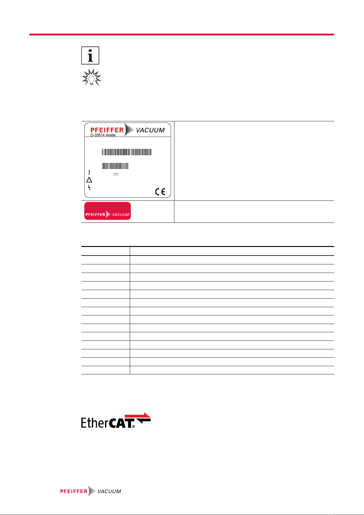
1.4.3 Stickers on the product
This section describes all the stickers on the product along with their meaning.
TM 700 EC
Made in Germany
Input:
Output:
Ser.-No.: 12345678
Mod.:
M.-No.:
48 V ± 10% DC 8.4 A
PM C01 854
0 - 48 V 9 A 0 - 1000 Hz
2018/01
Rating plate
The rating plate is located on the side of the electronic drive
unit.
warranty seal
Closure seal
The product is sealed ex-factory. Damaging or removing a clo-
sure seal results in loss of the warranty.
1.4.4 Abbreviations
Abbreviation Meaning in this document
AI / AO Analog Input / Analog Output
DCU Display Control Unit
DI / DO Digital Input / Digital Output
EC EtherCAT® interface
fRotation speed value of a vacuum pump (frequency, in rpm or Hz)
FE Functional earth
HPU Handheld Programming Unit
LED Light emitting diode
PPower
[P:xxx] Electronic drive unit parameter with number
PE Protective earth (earthed conductor)
tTime
TM Drive and magnetic bearing controller of the Turbopump
TPS Voltage supply (turbo power supply)
Tbl. 1: Abbreviations used in this document
1.5 Trademark proof
●EtherCAT® is a trademark and patented technology, licensed by Beckhoff Automation GmbH,
Germany.
About this manual
8/56
2 Safety
2.1 General safety information
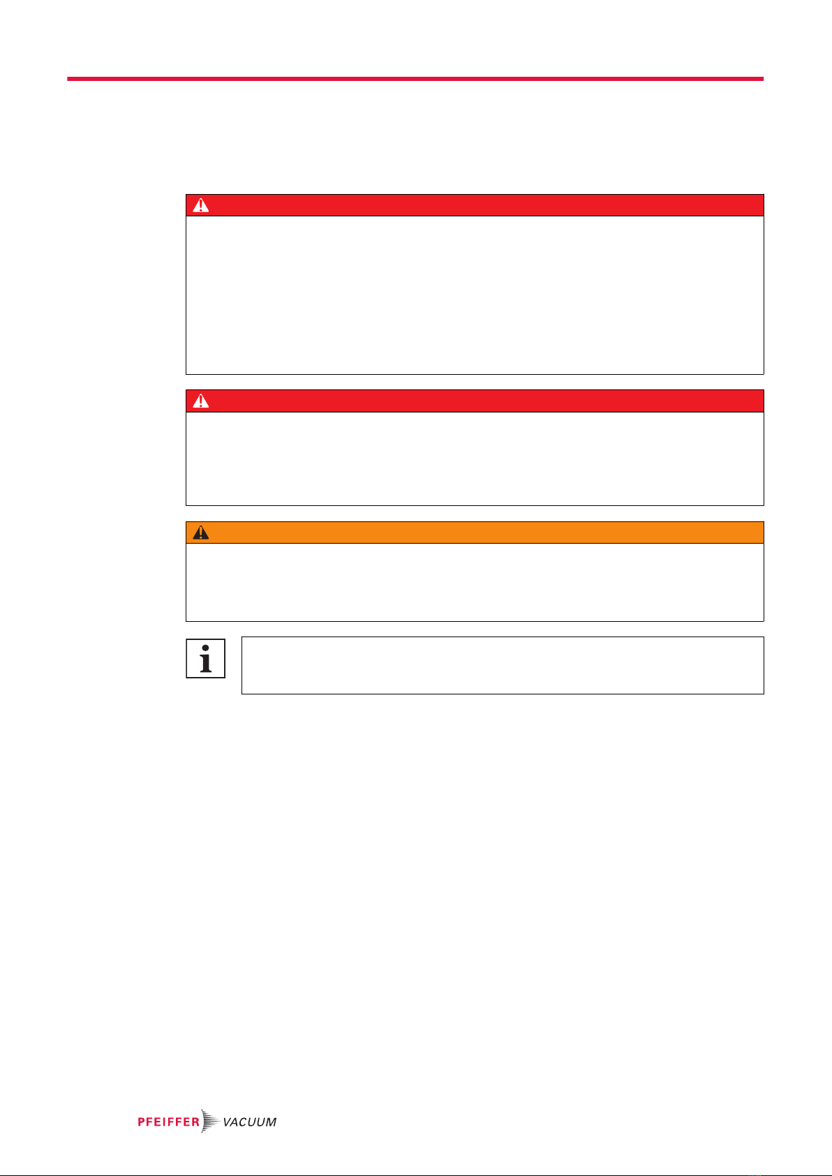
The following 4 risk levels and 1 information level are taken into account in this document.
DANGER
Immediately pending danger
Indicates an immediately pending danger that will result in death or serious injury if not observed.
►Instructions to avoid the danger situation
WARNING
Potential pending danger
Indicates a pending danger that could result in death or serious injury if not observed.
►Instructions to avoid the danger situation
CAUTION
Potential pending danger
Indicates a pending danger that could result in minor injuries if not observed.
►Instructions to avoid the danger situation
NOTICE
Danger of damage to property
Is used to highlight actions that are not associated with personal injury.
►Instructions to avoid damage to property
Notes, tips or examples indicate important information about the product or about this docu-
ment.
2.2 Safety instructions
All safety instructions in this document are based on the results of the risk assessment carried out in
accordance with Low Voltage Directive 2014/35/EU. Where applicable, all life cycle phases of the prod-
uct were taken into account.
Risks during installation
DANGER
Danger to life from electric shock
When establishing the voltages that exceed the specified safety extra-low voltage (according to IEC
60449 and VDE 0100), the insulating measures will be destroyed. There is a danger to life from elec-
tric shock at the communication interfaces.
►Connect only suitable devices to the bus system.
Safety
9/56

DANGER
Danger to life from electric shock
Power supply packs that are not specified or are not approved will lead to severe injury to death.
►Make sure that the power supply pack meets the requirements for double isolation between
mains input voltage and output voltage, in accordance with IEC 61010-1 IEC 60950-1 and
IEC 62368-1.
►Make sure that the power supply pack meets the requirements in accordance with IEC 61010-1
IEC 60950-1 and IEC 62368-1.
►Where possible, use original power supply packs or only power supply packs that correspond
with the applicable safety regulations.
WARNING
Risk of injury due to incorrect installation
Dangerous situations may arise from unsafe or incorrect installation.
►Do not carry out your own conversions or modifications on the unit.
►Ensure the integration into an Emergency Off safety circuit.
Risks during operation
NOTICE
Turbopump destruction due to gases with too high molecular masses
The pumping of gases with impermissible high molecular masses leads to the destruction of the tur-
bopump.
►Make sure that the gas mode is set correctly by [P:027] in the electronic drive unit.
►Consult Pfeiffer Vacuum before you use gases with higher molecular masses (> 80).
NOTICE
Property damage due to bearing wear after switching off incorrectly
Active magnetic bearings require a constant power supply. The motor acts as a generator and sup-
plies the drive electronics in the event of a power failure. Below a rotation speed of approx. 6,500
rpm, the kinetic energy of the rotor is no longer sufficient for supplying the magnetic bearing. The
electronic drive unit switches off. The rotor will run down audibly in the safety bearings.
►Do not switch off the pump by disconnecting the mains power supply.
►Always use the electric brake function after switching off the Turbopump.
2.3 Safety precautions
Duty to provide information on potential dangers
The product holder or user is obliged to make all operating personnel aware of dangers
posed by this product.
Every person who is involved in the installation, operation or maintenance of the product
must read, understand and adhere to the safety-related parts of this document.
Infringement of conformity due to modifications to the product
The Declaration of Conformity from the manufacturer is no longer valid if the operator
changes the original product or installs additional equipment.
●Following the installation into a system, the operator is required to check and re-evalu-
ate the conformity of the overall system in the context of the relevant European Direc-
tives, before commissioning that system.
General safety precautions when handling the product
►Use only power supply packs that comply with the applicable safety regulations.
►Observe all applicable safety and accident prevention regulations.
►Check that all safety measures are observed at regular intervals.
Safety
10/56

►Recommendation: Establish a secure connection to the earthed conductor (PE); protection class
III.
►Never disconnect plug connections during operation.
►Keep lines and cables away from hot surfaces (> 70 °C).
►Do not carry out your own conversions or modifications on the unit.
►Observe the unit protection class prior to installation or operation in other environments.
►Observe the protection class by ensuring the correct seating of the present sealing plugs.
►Disconnect the electronic drive unit only once everything has come to a complete standstill and
when the mains power supply of the turbopump is interrupted.
2.4 Limits of use of the product
Installation location weatherproof (internal space)
Air pressure 750 hPa to 1060 hPa
Installation altitude max. 2000 m
Rel. air humidity max. 80%, at T <31°C,
up to max. 50% at T <40°C
Protection class III
Overvoltage category II
Permissible protection class IP54
Degree of contamination 2
Ambient temperature +5°C to +40°C (with air cooling up to max. +35°C)
Tbl. 2: Permissible ambient conditions
Notes on ambient conditions
The specified permissible ambient temperatures apply to operation of the turbopump at
maximum permissible backing pressure or at maximum gas throughput, depending on the
cooling type. The turbopump is intrinsically safe thanks to redundant temperature monitor-
ing.
●The reduction in backing pressure or gas throughput permits operation of the turbo-
pump at higher ambient temperatures.
●If the maximum permissible operating temperature of the turbopump is exceeded, the
electronic drive unit first reduces the drive output and then switches it off where neces-
sary.
2.5 Proper use
●The electronic drive unit is used exclusively for the operation of Pfeiffer Vacuum turbopumps and
their accessories.
2.6 Foreseeable misuse
Misuse of the product invalidates all warranty and liability claims. Any use that is counter to the purpose
of the product, whether intentional or unintentional, is regarded as misuse, in particular:
●Operation with excessively high radiated heat output
●Use in areas with ionizing radiation
●Operation in potentially explosive atmospheres
●Use of accessories or spare parts that are not listed in these instructions
Safety
11/56
3 Product description
3.1 Identifying the product
►To ensure clear identification of the product when communicating with Pfeiffer Vacuum, always
keep all of the information on the rating plate to hand.
►Learn about certifications through test seals on the product or at www.certipedia.com with compa-
ny ID no. 000021320.
3.2 Product features
The electronic drive unit of type TM 700 EC represents a fixed component of the Turbopump. The pur-
pose of the electronic drive unit is to drive, monitor and control the entire pump.
Feature TM 700 EC
Supply voltage TM 48 V DC ±10 %
Connection panel EtherCAT®
Turbopumpe HiPace 300 M, 400 M, 700 M, 800 M
Tbl. 3: Features of the device variants
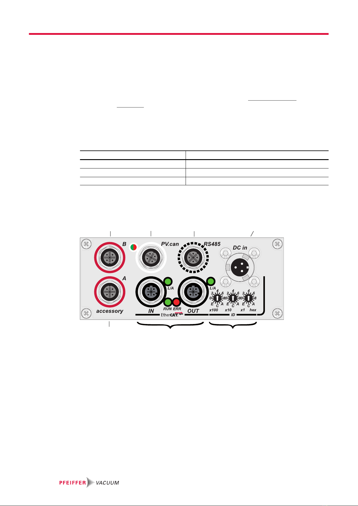
3.3 Function
2
1
5
6
34
7
Fig. 1: TM 700 EtherCAT connection panel
1 “accessory B” connector 5 “EtherCAT” coding switch device address
2 “PV.can” service connection 6 “EtherCAT” connectors
3 "RS-485" connector 7 “accessory A” connector
4 Connection "DC in"
3.4 Scope of delivery
●TM 700 EC
●Operating instructions
Product description
12/56
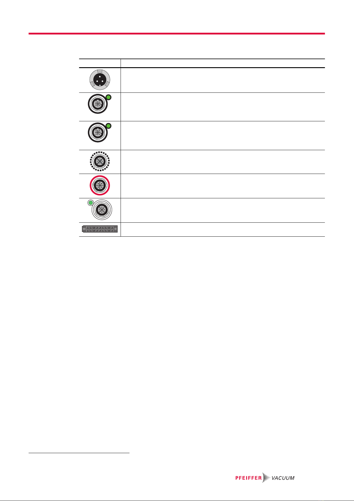
3.5 Connections
Connection Description
DC in
Housing connector with bayonet lock for the voltage supply between Pfeiffer Vac-
uum power supply packs and the electronic drive unit.
IN
L/A
EtherCAT IN
M12 socket (D coded) with threaded coupling and L/A-LED for connecting an in-
coming EtherCAT cable.
OUT
L/A
EtherCAT OUT
M12 socket (D coded) with threaded coupling and L/A-LED for connecting an Ether-
CAT cable to the next device.
RS-485
M12 socket with screw lock for the connection of Pfeiffer Vacuum control panels or
PC. The use of a Y-connector permits the integration into a bus system.
accessory1)
M12 socket with screw lock for the connection of Pfeiffer Vacuum accessories. The
use of a Y-connector permits the double pinout of a connector.
PV.can
M12 socket with screw lock and LED for the connection of an integrated pressure
measurement and for Pfeiffer Vacuum service purposes.
Device socket on the rear side of the electronic drive unit for the connection of the
turbopump.
Tbl. 4: Connection description of the electronic drive unit
1) The “accessory” connector is specified in the operating instructions for the pump.
Product description
13/56
4 Installation
4.1 Connection diagram
DANGER
Danger to life from electric shock
Power supply packs that are not specified or are not approved will lead to severe injury to death.
►Make sure that the power supply pack meets the requirements for double isolation between
mains input voltage and output voltage, in accordance with IEC 61010-1 IEC 60950-1 and
IEC 62368-1.
►Make sure that the power supply pack meets the requirements in accordance with IEC 61010-1
IEC 60950-1 and IEC 62368-1.
►Where possible, use original power supply packs or only power supply packs that correspond
with the applicable safety regulations.
DANGER
Danger to life from electric shock
When establishing the voltages that exceed the specified safety extra-low voltage (according to IEC
60449 and VDE 0100), the insulating measures will be destroyed. There is a danger to life from elec-
tric shock at the communication interfaces.
►Connect only suitable devices to the bus system.
WARNING
Risk of injury due to incorrect installation
Dangerous situations may arise from unsafe or incorrect installation.
►Do not carry out your own conversions or modifications on the unit.
►Ensure the integration into an Emergency Off safety circuit.
Contact load for the accessory connections to "accessory"
1. Maintain the maximum contact load of 200 mA per connection.
2. However, do not exceed the total sum of the load of all connections of 450 mA.
Installation
14/56
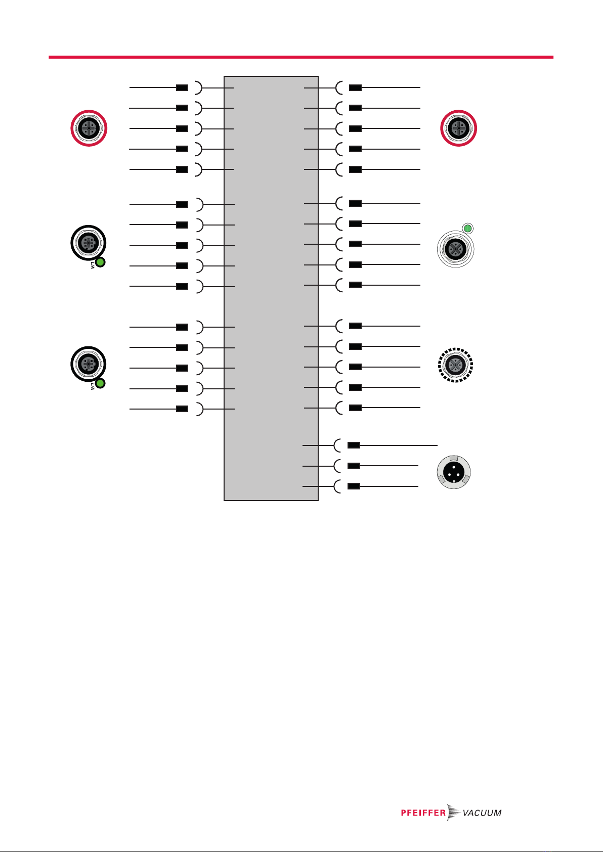
A C
B
4 1
5
23
32
5
1 4
13
4
2
4 1
23
4 1
23
A
B
C
DC in
1
2
3
4
5
1
2
3
4
5
1
2
3
4
5
1
2
3
4
5
1
2
3
4
5
1
2
3
4
5
accessory AEtherCAT INEtherCAT OUT
accessory BPV.canRS-485
24 V DC* out
RS 485 D +
RS 485 D -
n.c .
GND*
CAN-H
GND***
CAN-L
24 V DC***
FE
24 V DC**
FE
n.c.
24 V DC**
FE
n.c.
Tx+
Tx-
Rx-
n.c .
Rx+
Tx+
Tx-
Rx-
n.c .
Rx+
+ UB(+48 VDC ± 10 %)
FE
GND
B1
B2
A1
A2
Fig. 2: Connection diagram for TM 700 EC
4.2 EtherCAT® connector
You can use the “EtherCAT” connectors (2x 5-pin sockets, M12, D-coded) to connect the turbopump to
an EtherCAT bus system. The interface is galvanically safe and is isolated from the maximum supply
voltage for the electronic drive unit.
Installation
15/56
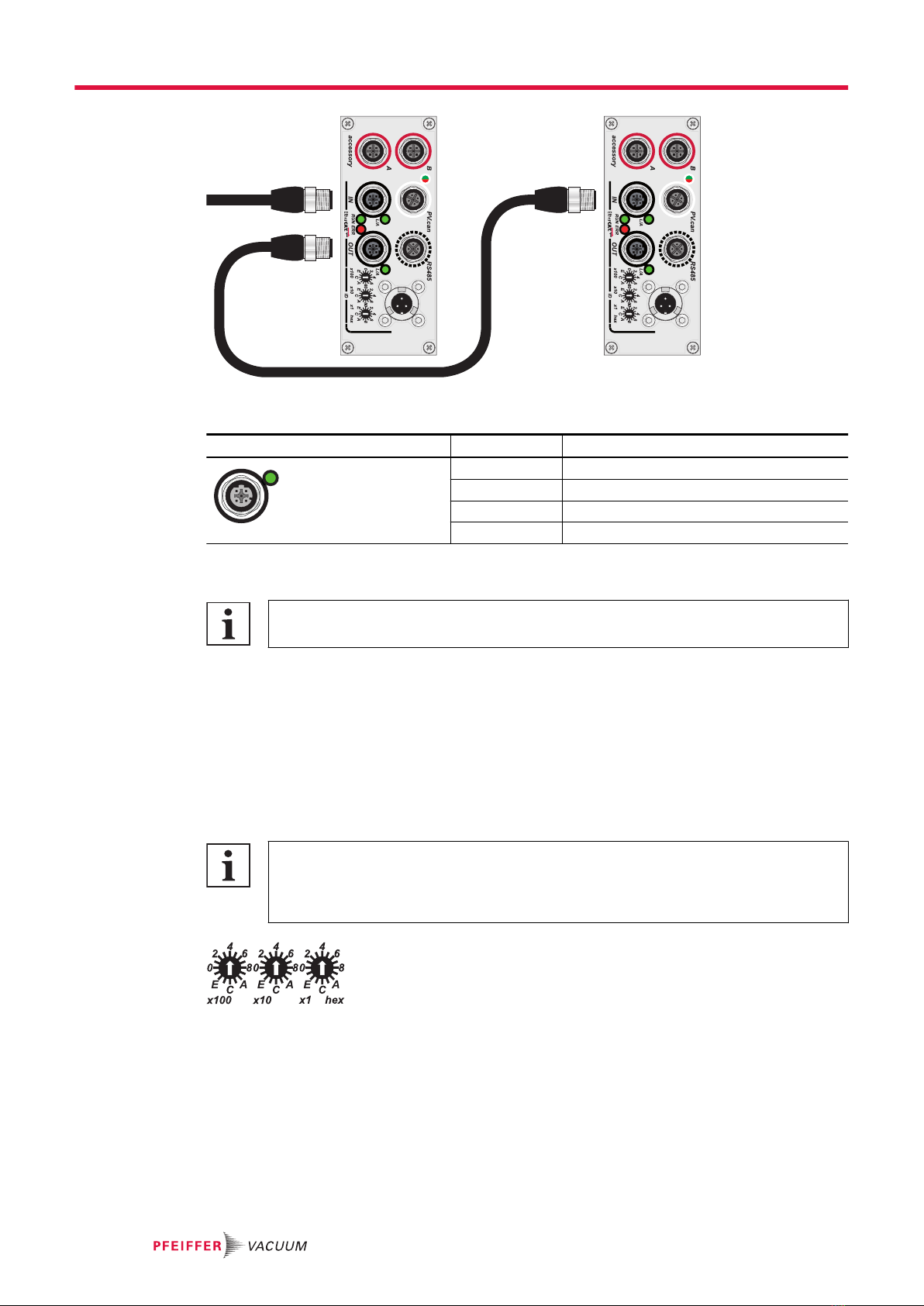
► IN ► IN
◄ OUT
Fig. 3: Example for an EtherCAT cable connection
Pin Assignment
L/A
1 2
4 3
1 Tx+
2 Rx+
3 Tx-
4 Rx-
Tbl. 5: EtherCAT interface, connection assignment
EtherCAT specification
The use of Ethernet switches and hubs is not supported.
Establish the cable connection
1. Connect the incoming cable from the control to EtherCAT IN.
2. Establish a bus connection to other devices via EtherCAT OUT.
3. Use the valid ESI file from Pfeiffer Vacuum for configuration.
4.2.1 Device identification
EtherCAT devices are always addressed using their position in the bus. There is no need to make con-
ventional address settings.
Additional identification in the bus
Under certain conditions, it may be beneficial to perform additional (manual) identification,
e.g., if there is a risk of mixing up multiple similar devices through incorrect cabling. Various
configuration options exist for this.
Fig. 4: Hexadecimal coding switch
Explicit device identification
Recommended method as no additional configuration programs are required.
1. Take the rubber plug off the address selector switches.
2. Select this identification in the projection.
3. Set the device ID to the projected value.
–Hexadecimal 001h to FFFh corresponds to decimal 1 to 4095.
–The new value is transferred from "Voltage on/off".
Installation
16/56
4. After replacing a device, use the ID of the older device.
5. Position the rubber plugs straight and as deep as possible to achieve the stated protection de-
gree.
Station alias
A suitable configuration program must be used as a prerequisite.
1. Select this identification in the projection.
2. Allocate the device online "Station alias".
–This new value applies after a "Reset".
3. Repeat this procedure after replacing a device.
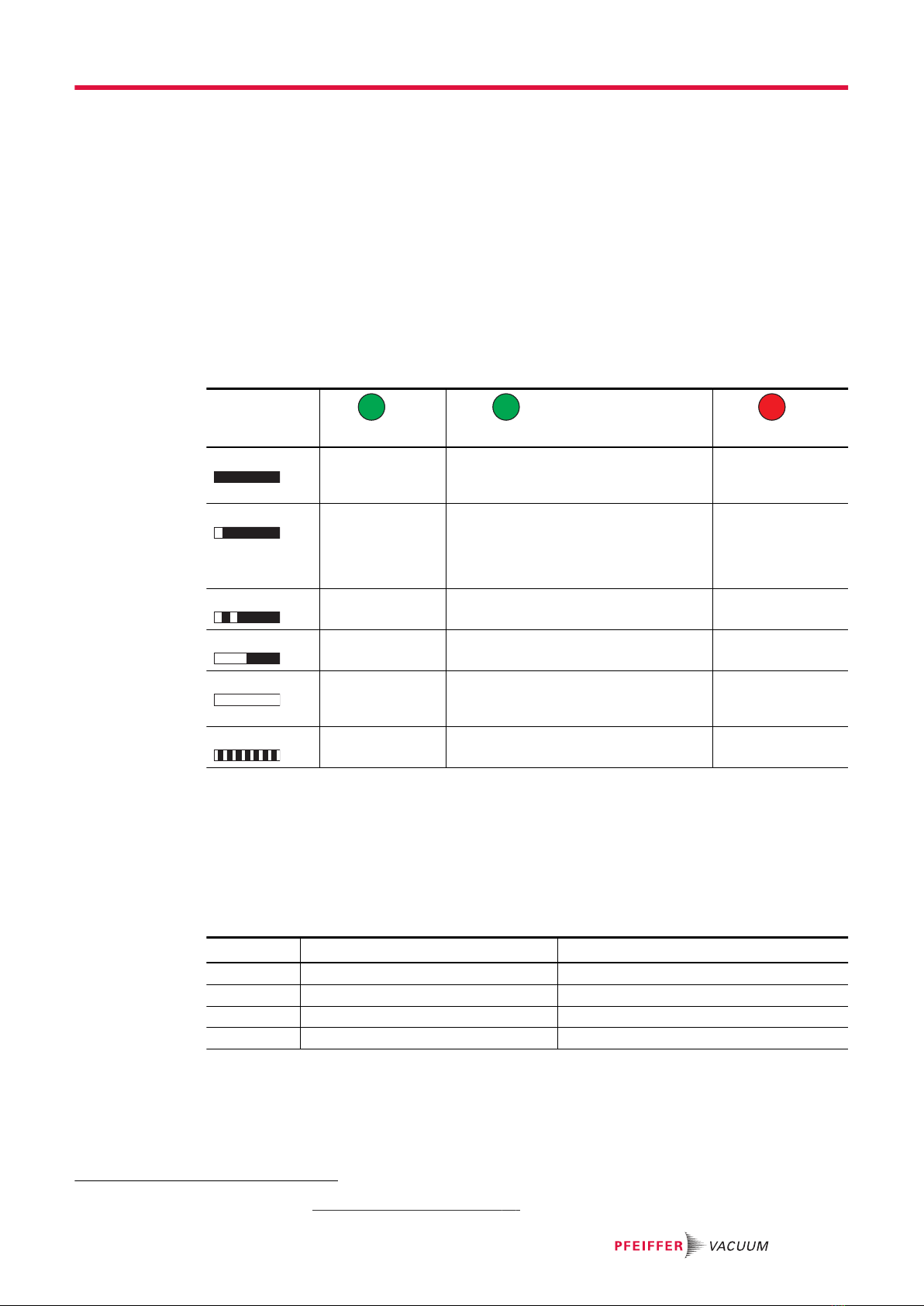
4.2.2 Operating mode display via LED
LEDs on the electronic drive unit show fundamental operating states of the Turbopump. A differentiated
malfunction and warning display is possible only for operation with control unit.
Display
L/A (green)
Connection
RUN (green)
EtherCAT status
ERR (red)
EtherCAT error
Off No connection "INIT":
● Initialization, no process or service
data
No error
Rapid flashing – "SAFE OPERATIONAL":
● Process input data (unit --> control)
is valid
● Output data (control --> unit) in a
safe state
Spontaneous sta-
tus change
Flashing 2x – – Connection lost
Flashing – "PRE_OPERATIONAL":
● Service data only, no process data
Invalid configura-
tion
Permanently on Connection to
next device, no
activity
"OPERATIONAL":
● Process input and output data is
valid
Bootstrap
Flickering Connection active "BOOTSTRAP" Booting error
Tbl. 6: Behavior and meaning of the LEDS of the EtherCAT interface
4.2.3 Process Data
Process output data
Process output data are:
●Default RxPDO (Control --> TM 700 EC, "output"), CoE 1600h.1 – 4 (1 Byte)
Byte.Bit CoE2) Meaning
0.0 7000.01 Turbo Start Stop Pumping station (0: off, 1: on)
0.1 7000.02 Turbo Reset Alarm 0 --> 1: Fault acknowledgement
0.2 7000.03 Turbo Low Speed Stand-by (0: off, 1: on)
0.3 – 7. Reserved
Tbl. 7: Process output data
Process input data
Process input data are:
●Default TxPDO (TM 700 EC --> Control, "input"), CoE 1A00h.1 – 11 (7 Byte)
2) Hexadecimal (see chapter “Service Data”, page 18)
Installation
17/56
Byte.Bit CoE3) Meaning
0.0 6000.01 Rotation Pump rotates > 60 min-1(0: no, 1: yes)
0.1 6000.02 Normal Normal operation (0: no, 1: yes)
0.2 6000.03 Acceleration Pump accelerates (0: no, 1: yes)
0.3 6000.04 Deceleration Pump decelerates (0: no, 1: yes)
0.4 6000.05 Remote / Local Control via EtherCAT (0: yes, 1: no)
0.5 6000.07 Turbo Low Speed Stand-by (0: off, 1: on)
0.6 6000.09 Alarm 0: no
1: yes
0.7 6000.0A Warning 0: no
1: yes
1. – 2. 6000.11 Turbo Speed 0.1 % of rated speed
3. – 4. 6000.12 Turbo Current 0.1 A
5. – 6. 6000.13 Turbo Pump Temperature °C
Tbl. 8: Process input data
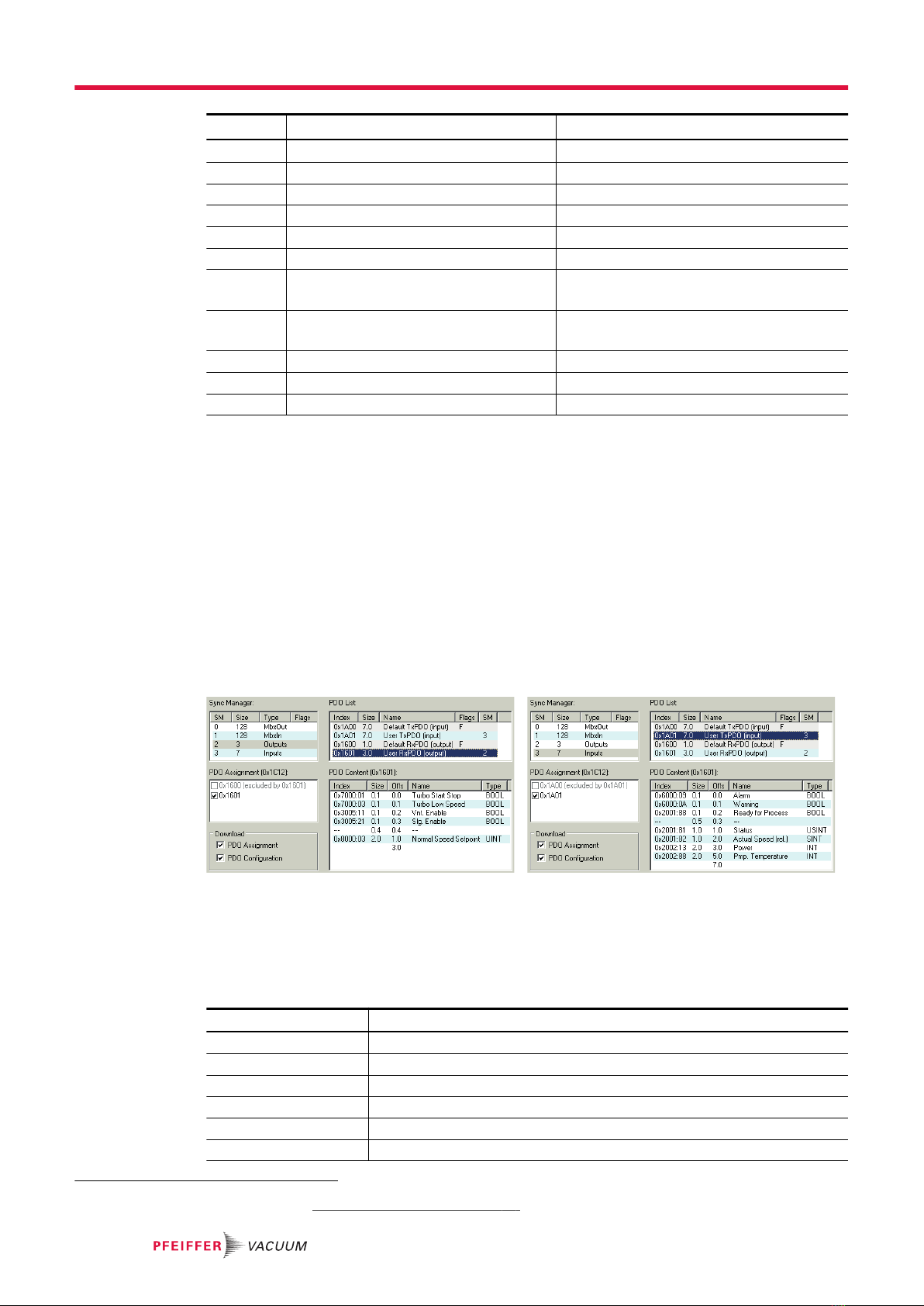
Compile process data alternative from CoE objects
1. Always conduct the state "PRE-OPERATIONAL".
2. Describe the object 1601h.0 or 1A01h.0 with 0.
3. Describe the object 1601h.1-n or 1A01h.1-n with corresponding CoE indices.
4. Use only objects marked with "P".
5. Assign the sub-index 1-n on a sequential basis only and without gaps.
6. Make sure that the data yields a total number of bytes (use pad bits if needed) and start with
whole bytes (exception BOOL).
7. Describe maximum 12 objects per PDO.
8. Describe the object 1601h.0 or 1A01h.0 with the number n of objects to be used.
9. Change object 1C12h.1 to 1601h or 1C13h.1 to 1A01h.
10. In the process data, select the corresponding PDO assignment 1601h or 1A01h.
Output data including 4 pad bits Input data including 5 pad bits
Tbl. 9: Example for a process data configuration
4.2.4 Service Data
Type Description
BOOL Binary value (yes/no)
BYTE( ) Single byte number
STRING( ) Character string
USINT Positive integer, 8 bit
UINT Positive integer, 16 bit
UDINT Positive integer, 32 bit
3) Hexadecimal (see chapter “Service Data”, page 18)
Installation
18/56

Type Description
ULINT Positive integer, 64 bit
SINT Integer, 8 bit
INT Integer, 16 bit
DINT Integer, 32 bit
REAL Floating point value, single precision
Tbl. 10: Data types of the service data
The following CoE objects are available for access to individual data objects (e.g., for configuration):
Administrative data (information about the device, communication)
Idx4) sIdx Name Type Access5) Description
1000 – Device Type UDINT RO
1008 – Manufacturer Device Name STRING( ) RO
1009 – Manufacturer Hardware Version STRING( ) RO
100A – Manufacturer Software Version STRING( ) RO
1010 01 Store Parameters UDINT RW
1011 01 Restore Default Parameters UDINT RW
1018 Identity Object
01 Vendor ID UDINT RO
02 Product Code UDINT RO
03 Revision Number UDINT RO
04 Serial number UDINT RO
10F8 – Timestamp Object ULINT RO
1600 01 - 04 Default RxPDO Mapping (1 - 4) UDINT RO See process
data
1601 00 User RxPDO Mapping USINT RW See process
data
x UDINT RW
1A00 01 - 0B Default TxPDO Mapping (1 - 11) UDINT RO See process
data
1A01 00 User TxPDO Mapping USINT RW See process
data
x UDINT RW
1C00 01 - 04 Sync Manager Communication Type USINT RO
1C12 00 Sync Manager 2 PDO Assignment USINT RW
01 UINT RW
1C13 00 Sync Manager 3 PDO Assignment USINT RW See process
data
01 UINT RW
F000 Semiconductor Device Profile
01 Index Distance UINT RO
02 Maximum Number of Modules UINT RO
F010 Module Profile Lists
01 UDINT RO
F9F0 – Manufacturer Serial Number STRING RO
F9F1 01 CDP Functional Generation Number (1) UDINT RO
F9F2 01 SDP Functional Generation Number UDINT RO
F9F3 – Vendor Name STRING( ) RO
4) Idx = Index, sIdx = Sub-index, Hexadecimal
5) RO = read only, RW = read/write, P = suitable for process data
Installation
19/56

Idx4) sIdx Name Type Access5) Description
F9F4 01 Semiconductor SDP Device Name (1) STRING( ) RO
F9F8 – FW Update Funct. Gen. Number (1) UDINT RO
Tbl. 11: Administrative data (information about the device, communication)
Input data (TM 700 EC --> Control)
Idx6) sIdx Name Type Access7) Description
2000 In Identity/Status
01 Manufacturer STRING( ) RO
02 Elc. Device Name STRING( ) RO
03 Elc. Serial Number STRING( ) RO
05 Firmware Version STRING( ) RO
08 Status Code UINT RO P 0: no error
1 - 999: Error 1 - 999
1001 - 1999: Warning 1 - 999
0A Elc. Operating Hours UDINT RO P h
82 Pmp. Device Name STRING( ) RO
8A Pmp. Operating Hours UDINT RO P h
8D Pmp. Cycles UDINT RO P
AB Brg. Wear USINT RO P %
BC Rot. Imbalance USINT RO P %
2001 In Operation
81 Speed Status USINT RO P 0: stopped (< 60 rpm)
1: accelerated
2: at rotation speed
3: delayed
82 Actual Speed (rel.) SINT RO P %
83 Actual Speed (abs.) DINT RO P min-1
88 Ready for Process BOOL RO P Rotation speed switch point
reached (0: no, 1: yes)
2002 In Pump Power/Temper-
ature
08 Elc. Temperature INT RO P °C
11 Voltage INT RO P 0.1 V
12 Current INT RO P 0.1 A
13 Power INT RO P W
18 Pwr. Temperature INT RO P °C
88 Pmp. Temperature INT RO P °C
98 Mot. Temperature INT RO P °C
A8 Brg. Temperature INT RO P °C
2004 In Component Identity/
Status
52 Prs1.DeviceName STRING( ) RO
62 Prs2.DeviceName STRING( ) RO
2005 In Component Operation
4) Idx = Index, sIdx = Sub-index, Hexadecimal
5) RO = read only, RW = read/write, P = suitable for process data
6) Idx = Index, sIdx = Sub-index, Hexadecimal
7) RO = read only, RW = read/write, P = suitable for process data
Installation
20/56
This manual suits for next models
1
Table of contents
Other Preiffer Industrial Equipment manuals


