Preface
Contents
Introduction ..............................................1-1
Overview .........................................................................................1-1
Specifications ..................................................................................1-2
Gloss Style Top Covers for Visconte 125W .................................1-5
External Locator - LCD Open .........................................................1-6
External Locator - Front, Left & Right Side Views ........................1-7
Bottom View ...................................................................................1-8
Mainboard Overview - Top (Key Parts) .........................................1-9
Mainboard Overview - Bottom (Key Parts) ..................................1-10
Mainboard Overview - Top (Connectors) .....................................1-11
Mainboard Overview - Bottom (Connectors) ...............................1-12
DC / DC Board Overview (Parts & Connectors) ..........................1-13
Audio Board Overview (Parts & Connectors) ..............................1-14
Disassembly ...............................................2-1
Overview .........................................................................................2-1
Maintenance Tools ..........................................................................2-2
Connections .....................................................................................2-2
Maintenance Precautions .................................................................2-3
Cleaning ..........................................................................................2-3
Disassembly Steps ...........................................................................2-4
Removing the Battery ......................................................................2-7
Removing the Hard Disk Drive .......................................................2-8
Removing the System Memory (RAM) ........................................2-10
Upgrading the Optical Device .......................................................2-11
Removing the Wireless LAN Module ...........................................2-12
Removing the Processor ................................................................2-13
Removing the PC Camera Module ................................................2-15
Removing the Keyboard & Shielding Plate ..................................2-16
Separating the Top & Bottom Cases ............................................ 2-17
Removing the Modem/Bluetooth Modem .................................... 2-19
Removing the Touchpad ............................................................... 2-20
Removing the LCD Front Panel Module ...................................... 2-21
Removing the Inverter .................................................................. 2-22
Removing the LCD Panel ............................................................. 2-23
Removing the Mainboard ............................................................. 2-25
Removing the Audio & DC / DC Boards ..................................... 2-26
Removing the PCMCIA Module .................................................. 2-27
Part Lists ..................................................A-1
Part List Illustration Location ....................................................... A-2
Top ................................................................................................ A-3
Bottom ........................................................................................... A-4
LCD ............................................................................................... A-5
Hard Disk Drive ............................................................................ A-6
QSI CD-ROM ............................................................................... A-7
Samsung CD-ROM ....................................................................... A-8
DVD-ROM .................................................................................... A-9
Combo ......................................................................................... A-10
Schematic Diagrams.................................B-1
System Block Diagram ................................................................... B-2
Socket 479-1 ................................................................................... B-3
Socket 479-2 ................................................................................... B-4
Montara GME-1 ............................................................................. B-5
Montara GME-2 ............................................................................. B-6
Montara GME-3 ............................................................................. B-7
DDR RAM CON ............................................................................ B-8
DDR Termination ........................................................................... B-9
Clock Generator ........................................................................... B-10
LVDS; CRT .................................................................................. B-11
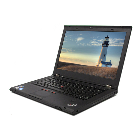
TECHNICAL SERVICE MANUAL Prestigio Visconte 125W
8

