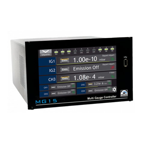
Prevac MG15 User manual

USER MANUAL
MG
MULTI GAUGE CONTROLLER


OPERATING MANUAL
English translation
MG
MULTI GAUGE CONTROLLER
Document no.
Rev.
May
Firmware version .
Precision and Vacuum Technology


MULTI GAUGE CONTROLLER Contents
Contents
INTRODUCTION
. INFORMATION ABOUT VERSION - RELEASE NOTE . . . . . . . . . . . . . . . . . . . .
. INTENDED USE . . . . . . . . . . . . . . . . . . . . . . . . . . . . . . . . . . . . . . . . .
. SAFETY . . . . . . . . . . . . . . . . . . . . . . . . . . . . . . . . . . . . . . . . . . . . .
.. PERSONNEL QUALIFICATIONS . . . . . . . . . . . . . . . . . . . . . . . . . . .
.. ILLUSTRATION OF RESIDUAL DANGERS . . . . . . . . . . . . . . . . . . . . .
.. GENERAL SAFETY INSTRUCTIONS . . . . . . . . . . . . . . . . . . . . . . . . .
.. GROUNDING . . . . . . . . . . . . . . . . . . . . . . . . . . . . . . . . . . . . . .
.. INTERNAL CIRCUITS OF DEVICE . . . . . . . . . . . . . . . . . . . . . . . . . .
.. SPARE PARTS AND MODIFICATIONS . . . . . . . . . . . . . . . . . . . . . . . .
.. VENTILATION . . . . . . . . . . . . . . . . . . . . . . . . . . . . . . . . . . . . .
.. OPERATION IN EXPLOSIVE ATMOSPHERES . . . . . . . . . . . . . . . . . . .
.. CLEANING . . . . . . . . . . . . . . . . . . . . . . . . . . . . . . . . . . . . . . .
. TECHNICAL DATA . . . . . . . . . . . . . . . . . . . . . . . . . . . . . . . . . . . . . . .
.. MECHANICAL DATA . . . . . . . . . . . . . . . . . . . . . . . . . . . . . . . . .
. SPECIFICATION . . . . . . . . . . . . . . . . . . . . . . . . . . . . . . . . . . . . . . . . .
.. TECHNICAL DATA . . . . . . . . . . . . . . . . . . . . . . . . . . . . . . . . . . .
.. OPERATION . . . . . . . . . . . . . . . . . . . . . . . . . . . . . . . . . . . . . .
.. STANDARDS . . . . . . . . . . . . . . . . . . . . . . . . . . . . . . . . . . . . . .
INSTALLATION
. UNPACKING . . . . . . . . . . . . . . . . . . . . . . . . . . . . . . . . . . . . . . . . . . .
. MECHANICAL INSTALLATION . . . . . . . . . . . . . . . . . . . . . . . . . . . . . . . .
. COOLING . . . . . . . . . . . . . . . . . . . . . . . . . . . . . . . . . . . . . . . . . . . .
. ELECTRICAL INSTALLATION . . . . . . . . . . . . . . . . . . . . . . . . . . . . . . . . .
.. POWER SUPPLY . . . . . . . . . . . . . . . . . . . . . . . . . . . . . . . . . . . .
.. MAINS SWITCH . . . . . . . . . . . . . . . . . . . . . . . . . . . . . . . . . . . .
.. GROUNDING TERMINAL . . . . . . . . . . . . . . . . . . . . . . . . . . . . . . .
. DEVICE REAR PANEL . . . . . . . . . . . . . . . . . . . . . . . . . . . . . . . . . . . . .
.. ACTIVE CHANNELS . . . . . . . . . . . . . . . . . . . . . . . . . . . . . . . . . .
.. PASSIVE CHANNELS . . . . . . . . . . . . . . . . . . . . . . . . . . . . . . . . .
.. REMOTE CONTROL . . . . . . . . . . . . . . . . . . . . . . . . . . . . . . . . .
.. I/O INTERFACE . . . . . . . . . . . . . . . . . . . . . . . . . . . . . . . . . . . .
.. RELAY OUTPUTS CONNECTION (SETPOINTS) . . . . . . . . . . . . . . . . . .
.. ADDRESS DIP SWITCH . . . . . . . . . . . . . . . . . . . . . . . . . . . . . . . .
OPERATION
. SWITCHING ON THE DEVICE . . . . . . . . . . . . . . . . . . . . . . . . . . . . . . . . .
. FRONT PANEL - STANDARD . . . . . . . . . . . . . . . . . . . . . . . . . . . . . . . . .
.. DISPLAY WITH TOUCH PANEL . . . . . . . . . . . . . . . . . . . . . . . . . . .
.. USB PORT CONNECTOR . . . . . . . . . . . . . . . . . . . . . . . . . . . . . . .
. FRONT PANEL - BLACK BOX . . . . . . . . . . . . . . . . . . . . . . . . . . . . . . . . .
. USER INTERFACE . . . . . . . . . . . . . . . . . . . . . . . . . . . . . . . . . . . . . . .
.. MAIN WINDOW . . . . . . . . . . . . . . . . . . . . . . . . . . . . . . . . . . . .
.. CHART WINDOW . . . . . . . . . . . . . . . . . . . . . . . . . . . . . . . . . . .
.. TIMER WINDOW . . . . . . . . . . . . . . . . . . . . . . . . . . . . . . . . . . .
.. NUMERIC KEYPAD . . . . . . . . . . . . . . . . . . . . . . . . . . . . . . . . . .
User manual rev. Page

Contents MULTI GAUGE CONTROLLER
.. ALPHANUMERIC KEYPAD . . . . . . . . . . . . . . . . . . . . . . . . . . . . . .
.. SETUP MENU . . . . . . . . . . . . . . . . . . . . . . . . . . . . . . . . . . . . .
.. SETUP SHORTCUTS . . . . . . . . . . . . . . . . . . . . . . . . . . . . . . . . . .
.. MESSAGES . . . . . . . . . . . . . . . . . . . . . . . . . . . . . . . . . . . . . . .
.. VIDEO PLAYER . . . . . . . . . . . . . . . . . . . . . . . . . . . . . . . . . . . .
. SETUP MENU . . . . . . . . . . . . . . . . . . . . . . . . . . . . . . . . . . . . . . . . . .
. MENU TREE . . . . . . . . . . . . . . . . . . . . . . . . . . . . . . . . . . . . . . . . . . .
.. GAUGE CONFIGURATION - SENSOR MENU . . . . . . . . . . . . . . . . . . . .
.. DEGASSING . . . . . . . . . . . . . . . . . . . . . . . . . . . . . . . . . . . . . .
.. EMISSION CONTROL - EMISSION CONTROL MENU . . . . . . . . . . . . . . .
.. READINGS CORRECTION OF GAS TYPE - GAS TYPE MENU . . . . . . . . . . .
.. FILTER . . . . . . . . . . . . . . . . . . . . . . . . . . . . . . . . . . . . . . . . .
.. CHANGING NUMBER OF DISPLAYED CHANNELS - DISPLAYED CHANNELS
MENU..........................................
.. CHANGING CHANNEL NAMES - CHANNEL NAMES MENU . . . . . . . . . . .
.. OUTPUTS SETTINGS . . . . . . . . . . . . . . . . . . . . . . . . . . . . . . . . .
.. TREND .........................................
.. DEVICE SETTINGS . . . . . . . . . . . . . . . . . . . . . . . . . . . . . . . . . .
.. COMMUNICATION SETTINGS - COMMUNICATION MENU . . . . . . . . . . .
.. DISPLAY SETTINGS . . . . . . . . . . . . . . . . . . . . . . . . . . . . . . . . . .
.. LANGUAGE MENU . . . . . . . . . . . . . . . . . . . . . . . . . . . . . . . . . . .
.. CHART ACTIVATION . . . . . . . . . . . . . . . . . . . . . . . . . . . . . . . . .
.. SAVING/LOADING SETTINGS . . . . . . . . . . . . . . . . . . . . . . . . . . . .
.. INFORMATION MENU . . . . . . . . . . . . . . . . . . . . . . . . . . . . . . . .
.. LOGS MENU . . . . . . . . . . . . . . . . . . . . . . . . . . . . . . . . . . . . . .
.. REBOOT . . . . . . . . . . . . . . . . . . . . . . . . . . . . . . . . . . . . . . . .
STEP BY STEP
. QUICK START . . . . . . . . . . . . . . . . . . . . . . . . . . . . . . . . . . . . . . . . . .
. COMMUNICATION INTERFACE CONFIGURATION . . . . . . . . . . . . . . . . . . . . .
. LANGUAGE SELECTION . . . . . . . . . . . . . . . . . . . . . . . . . . . . . . . . . . . .
TROUBLESHOOTING
. NOTIFICATIONS IN PRESSURE VALUE/INBFORMATION BOX . . . . . . . . . . . . . .
. MESSAGE BAR NOTIFICATIONS . . . . . . . . . . . . . . . . . . . . . . . . . . . . . . .
.. ERRORS . . . . . . . . . . . . . . . . . . . . . . . . . . . . . . . . . . . . . . . . .
.. .. WARNINGS . . . . . . . . . . . . . . . . . . . . . . . . . . . . . . . . . . .
. . NOTIFICATIONS IN MESSAGE BOX . . . . . . . . . . . . . . . . . . . . . . . . . . .
COMMUNICATION
. INTRODUCTION . . . . . . . . . . . . . . . . . . . . . . . . . . . . . . . . . . . . . . . .
.. CABLE SELECTION . . . . . . . . . . . . . . . . . . . . . . . . . . . . . . . . . .
.. PRECAUTIONS . . . . . . . . . . . . . . . . . . . . . . . . . . . . . . . . . . . . .
.. GROUNDING . . . . . . . . . . . . . . . . . . . . . . . . . . . . . . . . . . . . . .
. REMOTE ENABLE MODE . . . . . . . . . . . . . . . . . . . . . . . . . . . . . . . . . . .
. COMMUNICATION INTERFACES . . . . . . . . . . . . . . . . . . . . . . . . . . . . . . .
.. RS/RS CONNECTOR . . . . . . . . . . . . . . . . . . . . . . . . . . . . .
.. ETHERNET CONNECTOR . . . . . . . . . . . . . . . . . . . . . . . . . . . . . .
.. PROFINET CONNECTOR (OPTION) . . . . . . . . . . . . . . . . . . . . . . . . .
. MODBUS PROTOCOL . . . . . . . . . . . . . . . . . . . . . . . . . . . . . . . . . . . . .
.. INTRODUCTION . . . . . . . . . . . . . . . . . . . . . . . . . . . . . . . . . . . .
.. INTERFACE CONFIGURATION . . . . . . . . . . . . . . . . . . . . . . . . . . . .
Page User manual rev.

MULTI GAUGE CONTROLLER Contents
.. MODBUS RTU . . . . . . . . . . . . . . . . . . . . . . . . . . . . . . . . . . . . .
.. MODBUS TCP . . . . . . . . . . . . . . . . . . . . . . . . . . . . . . . . . . . . .
.. FUNCTION CODES . . . . . . . . . . . . . . . . . . . . . . . . . . . . . . . . . .
.. RESPONSE IN CASE OF ERROR . . . . . . . . . . . . . . . . . . . . . . . . . . .
.. TYPE OF DATA USED IN COMMUNICATION . . . . . . . . . . . . . . . . . . . .
.. TABLE OF MODBUS VARIABLES - MAP OF REGISTERS . . . . . . . . . . . . .
MAINTANCE AND SERVICE
. MAINTANCE . . . . . . . . . . . . . . . . . . . . . . . . . . . . . . . . . . . . . . . . . .
. CLEANING . . . . . . . . . . . . . . . . . . . . . . . . . . . . . . . . . . . . . . . . . . . .
. FIRMWARE UPGRADE . . . . . . . . . . . . . . . . . . . . . . . . . . . . . . . . . . . . .
.. AUTO UPDATE . . . . . . . . . . . . . . . . . . . . . . . . . . . . . . . . . . . . .
. PREBOOT ENVIRONMENT . . . . . . . . . . . . . . . . . . . . . . . . . . . . . . . . . .
.. BOOT MENU . . . . . . . . . . . . . . . . . . . . . . . . . . . . . . . . . . . . . .
.. TOOLS MENU . . . . . . . . . . . . . . . . . . . . . . . . . . . . . . . . . . . . .
.. NETWORK TAB . . . . . . . . . . . . . . . . . . . . . . . . . . . . . . . . . . . .
.. TEST TAB . . . . . . . . . . . . . . . . . . . . . . . . . . . . . . . . . . . . . . . .
STORAGE AND DISPOSAL
. PACKING . . . . . . . . . . . . . . . . . . . . . . . . . . . . . . . . . . . . . . . . . . . . .
. STORAGE . . . . . . . . . . . . . . . . . . . . . . . . . . . . . . . . . . . . . . . . . . . .
. DISPOSAL . . . . . . . . . . . . . . . . . . . . . . . . . . . . . . . . . . . . . . . . . . . .
APPENDIX
. DIP SWITCH ADDRESSING . . . . . . . . . . . . . . . . . . . . . . . . . . . . . . . . . .
User manual rev. Page

List of Tables MULTI GAUGE CONTROLLER
List of Tables
. Device speciication . . . . . . . . . . . . . . . . . . . . . . . . . . . . . . . . . . . . . .
. Description of pins of active channel socket. . . . . . . . . . . . . . . . . . . . . . . . .
. Description of pins of passive channel socket . . . . . . . . . . . . . . . . . . . . . . .
. Description of pins of I/O connection . . . . . . . . . . . . . . . . . . . . . . . . . . . .
. Description of Setpoints connector pins . . . . . . . . . . . . . . . . . . . . . . . . . .
. Weight of individual switches . . . . . . . . . . . . . . . . . . . . . . . . . . . . . . . .
. DIP switches functions . . . . . . . . . . . . . . . . . . . . . . . . . . . . . . . . . . . .
. Interface selection . . . . . . . . . . . . . . . . . . . . . . . . . . . . . . . . . . . . . . .
. DIP switches functions . . . . . . . . . . . . . . . . . . . . . . . . . . . . . . . . . . . .
. Interface selection . . . . . . . . . . . . . . . . . . . . . . . . . . . . . . . . . . . . . . .
. Identifying resistances for supported gauges . . . . . . . . . . . . . . . . . . . . . . .
. Correction factors for Bayard Alpert gaugest . . . . . . . . . . . . . . . . . . . . . . .
. Correction factors for Bayard Alpert gauges not implemented in the device . . . . .
. Notiications in pressure value/information box. . . . . . . . . . . . . . . . . . . . . .
. Pins description of ”RS/RS” connector . . . . . . . . . . . . . . . . . . . . . .
. Pins description of ”ETH” connector . . . . . . . . . . . . . . . . . . . . . . . . . . . .
. Pins description of ”PROFINET” connector . . . . . . . . . . . . . . . . . . . . . . . . .
. EIA Standard . . . . . . . . . . . . . . . . . . . . . . . . . . . . . . . . . . . . . . . . . .
. Connection parameters . . . . . . . . . . . . . . . . . . . . . . . . . . . . . . . . . . . .
. Modbus RTU frame format . . . . . . . . . . . . . . . . . . . . . . . . . . . . . . . . . .
. Modbus TCP frame format . . . . . . . . . . . . . . . . . . . . . . . . . . . . . . . . . .
. Modbus protocol function codes . . . . . . . . . . . . . . . . . . . . . . . . . . . . . . .
. Erros codes . . . . . . . . . . . . . . . . . . . . . . . . . . . . . . . . . . . . . . . . . . .
. Float IEEE- format in Modbus table . . . . . . . . . . . . . . . . . . . . . . . . . . .
. Example loat IEEE- value in Modbus table . . . . . . . . . . . . . . . . . . . . . .
. Basic registers table . . . . . . . . . . . . . . . . . . . . . . . . . . . . . . . . . . . . . .
. Communication registers map . . . . . . . . . . . . . . . . . . . . . . . . . . . . . . . .
. Digital outputs registers map . . . . . . . . . . . . . . . . . . . . . . . . . . . . . . . . .
. Additional registers map . . . . . . . . . . . . . . . . . . . . . . . . . . . . . . . . . . .
. Analogue outputs register map . . . . . . . . . . . . . . . . . . . . . . . . . . . . . . .
. Vacuum gauge types . . . . . . . . . . . . . . . . . . . . . . . . . . . . . . . . . . . . . .
. Vacuum gauges possible statuses . . . . . . . . . . . . . . . . . . . . . . . . . . . . . .
. Emission control options . . . . . . . . . . . . . . . . . . . . . . . . . . . . . . . . . . .
. Gas type options . . . . . . . . . . . . . . . . . . . . . . . . . . . . . . . . . . . . . . . .
. Setpoints source assignment options . . . . . . . . . . . . . . . . . . . . . . . . . . . .
. Digital outputs assignment options . . . . . . . . . . . . . . . . . . . . . . . . . . . . .
. Analogue outputs assignment options . . . . . . . . . . . . . . . . . . . . . . . . . . .
. Analogue outputs modes options . . . . . . . . . . . . . . . . . . . . . . . . . . . . . .
. Analogue outputs scales options . . . . . . . . . . . . . . . . . . . . . . . . . . . . . . .
. Storage parameters . . . . . . . . . . . . . . . . . . . . . . . . . . . . . . . . . . . . . .
. DIP Switch Addressing . . . . . . . . . . . . . . . . . . . . . . . . . . . . . . . . . . . .
Page User manual rev.

MULTI GAUGE CONTROLLER List of Figures
List of Figures
. Make sure that no objects enter through the vent holes of the device. Keep the device
dry. . . . . . . . . . . . . . . . . . . . . . . . . . . . . . . . . . . . . . . . . . . . . . . . .
. Dimensions . . . . . . . . . . . . . . . . . . . . . . . . . . . . . . . . . . . . . . . . . . .
. Three-conductor cable with protective ground and mains connection . . . . . . . . .
. View of the rear panel of the standard MG . . . . . . . . . . . . . . . . . . . . . . . .
. View of the rear panel of the MG with optional PROFINET interface. . . . . . . . .
. Active channel socket (RJ) . . . . . . . . . . . . . . . . . . . . . . . . . . . . . . . . .
. Passive channel socket (UTG-type) . . . . . . . . . . . . . . . . . . . . . . . . . . . . .
. Modbus RTU and TCP remote control module . . . . . . . . . . . . . . . . . . . . . . .
. ProiNet remote control module (option) . . . . . . . . . . . . . . . . . . . . . . . . .
. I/O socket (D-sub HD -pin female) . . . . . . . . . . . . . . . . . . . . . . . . . . . .
. Setpoints socket (D-Sub female) . . . . . . . . . . . . . . . . . . . . . . . . . . . . .
. Address DIP Switch . . . . . . . . . . . . . . . . . . . . . . . . . . . . . . . . . . . . . .
. Front panel . . . . . . . . . . . . . . . . . . . . . . . . . . . . . . . . . . . . . . . . . . .
. Front panel in BlackBox version . . . . . . . . . . . . . . . . . . . . . . . . . . . . . . .
. Three main device windows . . . . . . . . . . . . . . . . . . . . . . . . . . . . . . . . .
. Description of main window . . . . . . . . . . . . . . . . . . . . . . . . . . . . . . . . .
. Description of main window . . . . . . . . . . . . . . . . . . . . . . . . . . . . . . . . .
. Description of single vacuum channel . . . . . . . . . . . . . . . . . . . . . . . . . . . .
. Setpoints behaviour . . . . . . . . . . . . . . . . . . . . . . . . . . . . . . . . . . . . . .
. Setpoints settings . . . . . . . . . . . . . . . . . . . . . . . . . . . . . . . . . . . . . . .
. Gauge change . . . . . . . . . . . . . . . . . . . . . . . . . . . . . . . . . . . . . . . . . .
. Pressure unit change . . . . . . . . . . . . . . . . . . . . . . . . . . . . . . . . . . . . .
. Enlargement of pressure value window . . . . . . . . . . . . . . . . . . . . . . . . . .
. Chart module . . . . . . . . . . . . . . . . . . . . . . . . . . . . . . . . . . . . . . . . . .
. Adding data series and editing chart parameters . . . . . . . . . . . . . . . . . . . . .
. View of selected fragment of chart . . . . . . . . . . . . . . . . . . . . . . . . . . . . .
. Change of chart units . . . . . . . . . . . . . . . . . . . . . . . . . . . . . . . . . . . . .
. Notiication about detecting USB . . . . . . . . . . . . . . . . . . . . . . . . . . . . . .
. USB menu - chart data saving . . . . . . . . . . . . . . . . . . . . . . . . . . . . . . . .
. Chart activation menu . . . . . . . . . . . . . . . . . . . . . . . . . . . . . . . . . . . . .
. Correct activation of chart module . . . . . . . . . . . . . . . . . . . . . . . . . . . . .
. Entering system date . . . . . . . . . . . . . . . . . . . . . . . . . . . . . . . . . . . . .
. Timer setting . . . . . . . . . . . . . . . . . . . . . . . . . . . . . . . . . . . . . . . . . .
. Numeric keypad . . . . . . . . . . . . . . . . . . . . . . . . . . . . . . . . . . . . . . . .
. Increasing/Decreasing value via numeric keypad . . . . . . . . . . . . . . . . . . . . .
. Number in exponential form . . . . . . . . . . . . . . . . . . . . . . . . . . . . . . . . .
. Alphanumeric keypad . . . . . . . . . . . . . . . . . . . . . . . . . . . . . . . . . . . . .
. Device setup . . . . . . . . . . . . . . . . . . . . . . . . . . . . . . . . . . . . . . . . . .
. Set up shortcut in the setup menu . . . . . . . . . . . . . . . . . . . . . . . . . . . . . .
. Example use of shortcut . . . . . . . . . . . . . . . . . . . . . . . . . . . . . . . . . . . .
. Example warning and error messages. . . . . . . . . . . . . . . . . . . . . . . . . . . .
. Warning message . . . . . . . . . . . . . . . . . . . . . . . . . . . . . . . . . . . . . . .
. Error message . . . . . . . . . . . . . . . . . . . . . . . . . . . . . . . . . . . . . . . . .
. Multiple messages . . . . . . . . . . . . . . . . . . . . . . . . . . . . . . . . . . . . . . .
User manual rev. Page

List of Figures MULTI GAUGE CONTROLLER
. Menu bar - video player . . . . . . . . . . . . . . . . . . . . . . . . . . . . . . . . . . . .
. Video player - menu . . . . . . . . . . . . . . . . . . . . . . . . . . . . . . . . . . . . . .
. Deleting a video ile . . . . . . . . . . . . . . . . . . . . . . . . . . . . . . . . . . . . . .
. Video player . . . . . . . . . . . . . . . . . . . . . . . . . . . . . . . . . . . . . . . . . . .
. Notiication about detecting USB . . . . . . . . . . . . . . . . . . . . . . . . . . . . . .
. USB menu - list of videos on USB . . . . . . . . . . . . . . . . . . . . . . . . . . . . . .
. Copy *.avi to device . . . . . . . . . . . . . . . . . . . . . . . . . . . . . . . . . . . . . .
. Bayard Alpert Gauge . . . . . . . . . . . . . . . . . . . . . . . . . . . . . . . . . . . . . .
. Communication interface coniguration . . . . . . . . . . . . . . . . . . . . . . . . . .
. Language selection . . . . . . . . . . . . . . . . . . . . . . . . . . . . . . . . . . . . . . .
. Example of -conductor (+ screen) EIA connection . . . . . . . . . . . . . . . . .
. Maintaining communication - sequence diagram . . . . . . . . . . . . . . . . . . . . .
. Female socket of RS/RS (Modbus RTU) interface . . . . . . . . . . . . . . . .
. Female socket of Ethernet baseT (Modbus TCP) interface . . . . . . . . . . . . . .
. Female socket of ProiNet (Modbus RTU) interface . . . . . . . . . . . . . . . . . . . .
. Modbus RTU network structures model . . . . . . . . . . . . . . . . . . . . . . . . . .
. Checksum calculation algorithm . . . . . . . . . . . . . . . . . . . . . . . . . . . . . . .
. USB detected hint . . . . . . . . . . . . . . . . . . . . . . . . . . . . . . . . . . . . . . .
. USB menu . . . . . . . . . . . . . . . . . . . . . . . . . . . . . . . . . . . . . . . . . . . .
. Firmware list . . . . . . . . . . . . . . . . . . . . . . . . . . . . . . . . . . . . . . . . . .
. Restart message . . . . . . . . . . . . . . . . . . . . . . . . . . . . . . . . . . . . . . . .
. Updating irmware . . . . . . . . . . . . . . . . . . . . . . . . . . . . . . . . . . . . . . .
. Update summary example . . . . . . . . . . . . . . . . . . . . . . . . . . . . . . . . . .
. Auto update . . . . . . . . . . . . . . . . . . . . . . . . . . . . . . . . . . . . . . . . . .
. Auto update . . . . . . . . . . . . . . . . . . . . . . . . . . . . . . . . . . . . . . . . . .
. Enter into preboot environment . . . . . . . . . . . . . . . . . . . . . . . . . . . . . . .
. Boot menu . . . . . . . . . . . . . . . . . . . . . . . . . . . . . . . . . . . . . . . . . . .
. Switch software version . . . . . . . . . . . . . . . . . . . . . . . . . . . . . . . . . . . .
. Message box conirming the changed settings . . . . . . . . . . . . . . . . . . . . . . .
. Tools menu . . . . . . . . . . . . . . . . . . . . . . . . . . . . . . . . . . . . . . . . . . .
. Selecting additional tool . . . . . . . . . . . . . . . . . . . . . . . . . . . . . . . . . . . .
. Network tab . . . . . . . . . . . . . . . . . . . . . . . . . . . . . . . . . . . . . . . . . . .
. Numeric panel . . . . . . . . . . . . . . . . . . . . . . . . . . . . . . . . . . . . . . . . .
. Test tab . . . . . . . . . . . . . . . . . . . . . . . . . . . . . . . . . . . . . . . . . . . . .
Page User manual rev.

MULTI GAUGE CONTROLLER INTRODUCTION
INTRODUCTION
Please read this manual carefully to ensure the optimum operating conditions and safety of the
user. This user manual handbook contains important information about functionality, installation,
start-up and operation of the MG device.
. INFORMATION ABOUT VERSION - RELEASE NOTE
Information about MG device version can be found at www.prevac.eu, in the DOWNLOAD tab.
There is information about any possible changes in subsequent versions of the device or software.
. INTENDED USE
The MG multi gauge controller is a universal devices controlled by a microprocessor, able to sup-
port several types of pressure gauges in a range of mbar to mbar (depending on the
gauge used). The concept and design of the controller enable stable and reliable integration of the
comprehensive process control systems. The MG is able to support up to seven gauges, includ-
ing up to three passive and four active gauges. Optionally, the user may on placing an order choose
the number of supported passive (with hot cathode) and an additional communication interface
(ProiNet). In further part of the manual the device will be referred to as the ”MG”.
. SAFETY
The owner of the device must ensure that all the users have been informed about the safety require-
ments contained in this manual. In the event of sale or transfer of the device to another owner this
manual should be attached.
.. PERSONNEL QUALIFICATIONS
All work described in this document may only be carried out by persons who have suitable technical
training and the necessary experience or who have been instructed by the inal user of the device.
.. ILLUSTRATION OF RESIDUAL DANGERS
This user manual illustrates safety notes concerning dangers as follows:
. Information on potential serious accident or personal injury.
User manual rev. Page

INTRODUCTION MULTI GAUGE CONTROLLER
. Information on possible damage to the device.
. Information on correct handling or use. Disregarding safety notes can lead to malfunctions
or device damage.
. Note. Indicates particularly important, but not safety-relevant information.
.. GENERAL SAFETY INSTRUCTIONS
The MG has been designed to maximally protect the user and his environment against burns or
electric shocks, mechanical hazards, high temperature and ire spreading out of the device. The
environmental conditions different from those speciied below may pose a threat to the user and
his environment:
• Use inside buildings.
• Elevation above sea level of up to metres.
• Temperature range of safe operation: °C do °C.
• Maximum relative humidity: % (to °C), decreased linearly down to max. % at °C.
• Fluctuations of supply voltage cannot exceed ±% of the rated value.
• Protection class .
During all the operations carried out with the use of the device described in this manual, observe
the applicable safety regulations. Observe all the safety notes given in this document and forward
the information to all other users of the device. Pay particular attention to the following safety
notes:
Supply voltage..
Contact with live parts is extremely hazardous when any objects are introduced
or any liquids penetrate into the device.
Make sure that no objects enter through the vent holes of the device. Keep the
device dry.
Page User manual rev.

MULTI GAUGE CONTROLLER INTRODUCTION
Fire of device.
If smoke or lames coming from the device are sighted, disconnect power sup-
ply immediately (by unplugging the power cord, or if it is not possible by dis-
connecting a relevant circuit in the switchboard powering the device). Remove
lammable materials at a safe distance. Start extinguishing the ire. If the power
supply could not be disconnected use only E-type extinguishers or dry-powder
extinguishers designed to extinguish equipment under voltage.
Improper installation, operation or use.
Improper installation, operation or use may damage the MG . Strictly adhere
to the stipulated installation and operation data.
Self-coniguration of the device.
Self-coniguration of the MG by the user through the service application re-
sults in waiver of the PREVAC’s liability for proper functioning of the device.
Figure .: Make sure that no objects enter through the vent holes of the device. Keep the device
dry.
Failure to observe the general safety instructions may result in potentially dangerous situa-
tions.
User manual rev. Page

INTRODUCTION MULTI GAUGE CONTROLLER
.. GROUNDING
The MG is the class device. To minimize a risk of electric shock connect the device to the mains
with a -conductor mains cable. Conductor cross-section should be min. mm (AWG). Plug the
mains cable into wall sockets with protective ground only.
.. INTERNAL CIRCUITS OF DEVICE
The operating personnel cannot remove the device covers. The device does not contain any inter-
nal control systems and replaceable elements, which could be operated by unauthorized persons.
Replace any attached components only after disconnecting the mains cable. To avoid electric shock
always disconnect the mains cable, any external voltage sources and discharge the output circuits.
.. SPARE PARTS AND MODIFICATIONS
Replacement of spare parts, modiications and repairs may be carried out only by the PREVAC’s
authorized personnel. Therefore, the device must be delivered to the PREVAC’s service.
.. VENTILATION
The device has vent holes located on the side panels of the enclosure. Do not cover the vent holes
during the operation of the device.
.. OPERATION IN EXPLOSIVE ATMOSPHERES
Operation in explosive atmospheres.
The device cannot be used in the presence of lammable gases or vapours. The
device cannot be used in potentially explosive atmospheres.
.. CLEANING
Keep the device dry. For cleaning device’s enclosure, use only moistened cloth. Do not use any
aggressive or abrasive cleaning agents.
Page User manual rev.

INTRODUCTION MULTI GAUGE CONTROLLER
. SPECIFICATION
.. TECHNICAL DATA
PARAMETER DESCRIPTION
ELECTRICAL PARAMETERS
Power supply - VAC
Frequency - Hz
Current consumption .A (V)
.A (V)
Maximum power consumption W
Protection class I
Overvoltage category II
Power supply connection socket European connection socket IEC C
Fuse .A (V)
.A (V)
MEASUREMENT CHANNELS
Measurement channels active channels
up to * passive channels
Supported active gauges** CTR, TTR, TTR, PTR, PKR, PCR,
PTR, ITR, ITR, Baratron, ANALOG IN,
PG, ATMION
Supported passive gauges** IE, IE, UHV-, UHV-p, MKS Series ,
NUDE-UHV-A, NR-F-UHV, G
MEASUREMENT RANGE
Active gauges xmbar (depending on type)
Passive gauges xmbar (depending on type)
VOLTAGE MEASUREMENT SPECIFICATION
Resolution of converter .V
Accuracy of measurement V
Sampling frequency sps
CURRENT MEASUREMENT SPECIFICATION
Resolution of converter .fA
continued on next page
Page User manual rev.

MULTI GAUGE CONTROLLER INTRODUCTION
continued from previous page
PARAMETER DESCRIPTION
Accuracy of measurement fA***
Sampling frequency sps
Screen refreshment sps
Temperature drift Automatically adjusted by internal temperature
control
GAUGE CONNECTION
Active gauge RJ
Passive gauge UTGSVDEU + BNC
COMMUNICATION
Communication interfaces RS/, Ethernet, PROFINET*
I/O
Digital inputs
Digital outputs
Analogue outputs (-V)
AMBIENCE
Operating temperature range + ºC - + ºC
Storage temperature range ºC - + ºC
Relative humidity Max. % (to °C), decreased linearly down to max.
% (at °C)
MECHANICAL PARAMETERS
Dimensions Width: . mm
Height: . mm
Depth: . mm
Weight . kg
Installation Rack mounted or Desktop device
(*) - optional
(**) - additional gauges can be deined, see section ... or ....
(***) - at lowest range (highest vacuum).
Table .: Device speciication
User manual rev. Page

INTRODUCTION MULTI GAUGE CONTROLLER
.. OPERATION
The device can be controlled in two ways:
• Manually on the display with touch panel.
• Remotely via RS, RS or Ethernet, see chapter ...
.. STANDARDS
• The MG conforms to the following standards and harmonised standards:
–PN-EN -:- (EN -:) - Electrical equipment for measurement,
control and laboratory use - EMC requirements - Part : General requirements.
–PN-EN --:/A: (EN --:/A:) - Electromagnetic com-
patibility (EMC) – Part -: General standards – Emission standard for industrial envi-
ronments.
–PN-EN -: (EN -:) - Safety requirements for electrical equip-
ment for measurement, control and laboratory use - Part : General requirements.
• Conforms to the essential requirements of the following directives
–EMC //EU - Directive //EU of the European Parliament and of the Coun-
cil of February on the harmonisation of the laws of the Member States relating
to electromagnetic compatibility
–LVD //EU - Directive //EU of the European Parliament and of the Council
of February on the harmonisation of the laws of the Member States relating
to the making available on the market of electrical equipment designed for use within
certain voltage limits.
Page User manual rev.

MULTI GAUGE CONTROLLER INSTALLATION
INSTALLATION
This chapter describes the procedures for unpacking, mechanical installation and electrical instal-
lation. Take care when lifting the unit that the weight and position do not exceed comfortable limits.
. UNPACKING
. Visually inspect the transport packaging for signs of external damage.
. Unpack the MG .
Note: Retain the packaging materials for later use. The MG must be stored and trans-
ported in the original packaging material only.
. Examine the MG for completeness.
. Visually inspect the MG for signs of damage.
Damaged product.
Using the destroyed or damaged device or connection cables can result in elec-
tric shock. Never attempt to put a damaged product into operation. Secure
the damaged product from unintended operation. Send a damage report to the
courier company or the insurer.
. MECHANICAL INSTALLATION
The MG device can be mounted in a DIN (”, HU) cabinet/rack, occupying half of its
width. In each of these cases you must pay attention to the following safety note.
Ambient temperature.
Exceeding the maximum permitted ambient temperature may damage the de-
vice.
Before switching on the device, make sure that the maximum permitted ambi-
ent temperature is not exceeded and that the air can low freely through the
vent holes.
Do not expose the device to direct sun.
User manual rev. Page

INSTALLATION MULTI GAUGE CONTROLLER
Protection class of the rack.
If the product is installed in a rack, the protection class of the rack (protection
from foreign bodies and water) is likely to be lowered, e.g. according to the EN
- regulations for switching cabinets.
Take appropriate measures to restore the required protection class of the rack.
. COOLING
The MG is equipped with a cooling system. The power unit is equipped with a suction fan. Air is
supplied from the panels located by the power unit enclosure. Hot air outlet is located on the rear
panel. At least mm should be ensured to let air get inside from the side panels. The MG should
not be operated at temperatures exceeding °C.
. ELECTRICAL INSTALLATION
.. POWER SUPPLY
The main mains connection is an IEC socket on the rear wall of the device. The MG enclosure
is grounded to protect the user against electric shock. Always connect the device to a socket with
protective ground. If necessary, contact an electrician before connecting the device. A suitable
mains cable is supplied with the device. If the plug is not compatible with the socket, use a suitable
mains cable:
• Three-conductor cable with protective ground.
• Conductor cross-section should be min. mm(AWG).
Figure .: Three-conductor cable with protective ground and mains connection
Page User manual rev.
Other manuals for MG15
1
Table of contents
Other Prevac Controllers manuals

