Prior Scientific PLW20 User manual

More to Prior than meets the eye
PLW20
Well Plate Loader
Manual
www.prior.com
H4648 V3.0

PLW20 Manual V3.02
CONTENTS
SECTION 1 – SAFETY INFORMATION 3
1.1 Important Safety Information 3
1.2 General Guidelines for Use or Operation 4
SECTION 2 – SPECIFICATIONS 6
SECTION 3 – UNPACKING 7
3.1 Unpacking and Inspecting 7
3.2 System Integration 7
3.3 Packing 8
SECTION 4 – IDENTIFYING YOUR SYSTEM 9
4.1 System Diagram 9
4.2Plateloadermovementandaxisidentication 10
4.3ConnectionIdentication 10
SECTION 5 – INSTALLATION 11
5.1 Installing your system 11
5.2 Installing the stage onto the microscope 15
SECTION 6 – SETUP OF THE PLW20 18
6.1 Software 18
6.2 Software Screen 18
6.3 Starting setup 18
6.4SetupofthePLW20 20
SECTION 7 – OPERATION OF THE PLW20 28
7.1 Using the Software 28
7.2TestingaSetupviaSingleStepMoves 30
7.3 Testing a Setup via a Soak Test 31
7.4 Typical Screenshots 32
SECTION 8 – ROUTINE MAINTENANCE 34
SECTION 9 – SOFTWARE INTEGRATION 35
SECTION 10 – TROUBLESHOOTING 36
SECTION 11 – RETURNS AND REPAIRS 38

More to PRIOR than meets the eye
www.prior.com 3
SECTION 12 – APPENDIX 39
Appendix A – Using Prior Terminal
Appendix B – Fitting a barcode reader
Appendix C – Using a barcode reader

PLW20 Manual V3.04
Section 1
SAFETY INFORMATION
1.1 IMPORTANT SAFETY INFORMATION
SAFETY WARNINGS
Always observe the following safety precautions
• ThePLW20mustonlybeconnectedtoapoweroutlet,whichprovidesaprotective
earth.
• Useonlythemainscordsupplied.Ifthisdoesnottyourpoweroutlet,contactyour
distributor for the correct power lead.
• The unit is heavy and weighs 32kg. Remove the microscope before transporting. It
should only be lifted by two people: use side handle and lip of the rear cable entry area
to lift safely.
• Always disconnect the equipment before moving.
• Thisequipmentisforuseinmoderate,indoorconditionsonly.NEVERusethe
equipment in damp or wet conditions.
• Avoidexcessiveheat,humidity,dust&vibration.
• Do not use where the equipment may be subjected to dripping or splashing liquids.
• Thisequipmentcontainsnouser-serviceableparts.Referallrepairstoqualiedservice
personnel.
• KeepngersandhandsclearofthePLW20’smovingpartswhenitisoperating.
• It is the user/operators responsibility to ensure good laboratory practise is followed if
well plates contain hazardous material.

More to PRIOR than meets the eye
www.prior.com 5
SAFETY SYMBOLS
Retain these instructions. The following symbols mean:
Warning: read instructions to understand possible hazard
Warning: hazardous voltage
Safety- System Integration
The Prior PLW20 is designed and assessed to have no serious
hazards. However it is always used as a component within a
complete microscopy system.
1.2 GENERAL GUIDELINES FOR USE/OPERATION.
ThePLW20formspartofanautomatedmicroscopysystem,whichmaybeusedinresearch
orproductionlaboratories.Itwillpick-up,present,sortandreturnplatestoeitherofthetwo
preloaded racks that are positioned at the front.
Whilstoperatingifaplatebecomesmisaligned,donotattempttocorrectthisduring
theoperationcycle.Turnothemainspowerbeforecorrectingplatepositionorremoving
any obstruction. Reinitialise the system.
ThePLW20rotaryarmmaymoveunexpectedly,underautomaticcontrol.

PLW20 Manual V3.06
Be aware that when using with a Nikon Ti microscope that you will need
to ensure that the objectives and condenser will not clash with the loader
system.We highly reccomend speaking to a product specialist to ensure
no damage occurs to any instrument.
ThesystemshouldONLYbeusedwithanEXTRA LONG WORKING DISTANCE
condenser.TheLONGWORKINGDISTANCEcondenserisnotsuitable.
ThefollowingobjectivesaresuggestedbyNikontobesuitableforusewiththePLW20.Be
carefulwhenusinganyobjectivewithaworkingdistanceoflessthan50mm.
MRH20041 CFIPlanFluorDL4XFN.A.0.13,W.D.16.4mm,PhL
MRH20101 CFIPlanFluorDL10XFN.A.0.30,W.D.15.2mm,Ph1
MRH48230 CFISuperPlanFluorELWDADM20XCN.A.0.45,W.D.8.2-6.9mm,PH-1
MRH48430 CFISuperPlanFluorELWDADM40XCN.A.0.60,W.D.3.6-2.8mm,PH-2
MRF00040 CFISFluor4XN.A.0.20,W.D.15.5mm
MRD00025 CFIPlanApochromatLambda2XN.A.0.10,W.D.8.5mm
MRD00045 CFIPlanApochromatLambda4XN.A.0.20,W.D.20mm
MRL00042 CFIPlanAchromat4XN.A.0.10,W.D.30.0mm
Oil objectives should be used only with extreme caution – consult a specialist before
proceeding.
Mercury bulbs MUST NOT be used with this system.
Ifusingacamera,itmustbemountedonthelefthandsideofthemicroscope.

More to PRIOR than meets the eye
www.prior.com 7
Section 2
SPECIFICATIONS
Thisequipmentisforindooruseandwillmeetitsperformancegureswithinanambient
temperaturerange5to40°Cwithmaximumrelativehumidityof80%humidity(deteriorating
linearlyto50%above31ºC).
• Size570mmdeepx850mmwidex680mhigh
• Weight57Kggross,(includesPlateloader,allaccessoriesandpackaging).32KgNet
(plateloaderfullyassembledwithaccessories,butnopackaging).Theweightofthe
microscopeisnotincludedinthesegures.
• Capacityof20slides(2racksof10).
• Plate type Standard well plates with and without covers.
• Plate change time of 28 seconds.
• InputVoltage100vto240v.
• Fuse rating for both fuses is T2A.
• CommunicationViaUSB.

PLW20 Manual V3.08
Section 3
UNPACKING
3.1 UNPACKING AND INSPECTING
CarefullyunpackthePLW20andretainthepackagingshouldtheunitneedtobereturned.
IfthePLW20appearsdamagedinanyway,returnittoyoursalesoutletinitsoriginal
packaging.Noresponsibilityfordamagearisingfromtheuseofnon-approvedpackaging
willbeaccepted.Thepackagingincludesapallet,userappropriatepalletliftingequipmentto
transportthePLW20inthepackaging.
Ensureallitemsandaccessoriesspeciedarepresent.
• PLW20slideloaderandmicroscopemountingplate
• 10positionwellplatehotel(x2)
• Installation/Operating manual
• Microscope Fitting kit
• Cables(mains&USB)
Ifnot,contactyoursalesoutletorPriorScientic.
Useonlyasspeciedbytheseoperatinginstructionsortheintrinsicprotectionprovidedby
the unit may be impaired.
3.2 SYSTEM INTEGRATOR
ThePriorPLW20isdesignedandassessedtohavenoserioushazards.
However it is always used as a component within a complete microscopy
system.
The PC terminal must be positioned close to the plate loader so that the PC operator has a
clear,unobstructedviewoftheplateloader.ThisensuresthatthePCoperatorwillbeaware
ofanypersonorobstructionsinthevicinityoftheplateloadersmovingparts,beforestarting
the loader. A red Fast Stop button can be found on the front of the Plate loader. This can be
usedtoinstantlycutthepowertotheloader,immediatelyhaltinganyarmmovements.
More to PRIOR than meets the eye
www.prior.com 9
Iftheplateloaderistobeoperatedremotely,viaaweblinketc.thenadequate
procedures should be put in place to either ensure that the operator can view the plate
loader,orensurethatnountrainedpersonnelhaveaccess.
Read the information in Section 1.2 regarding objective and condenser compatibility.
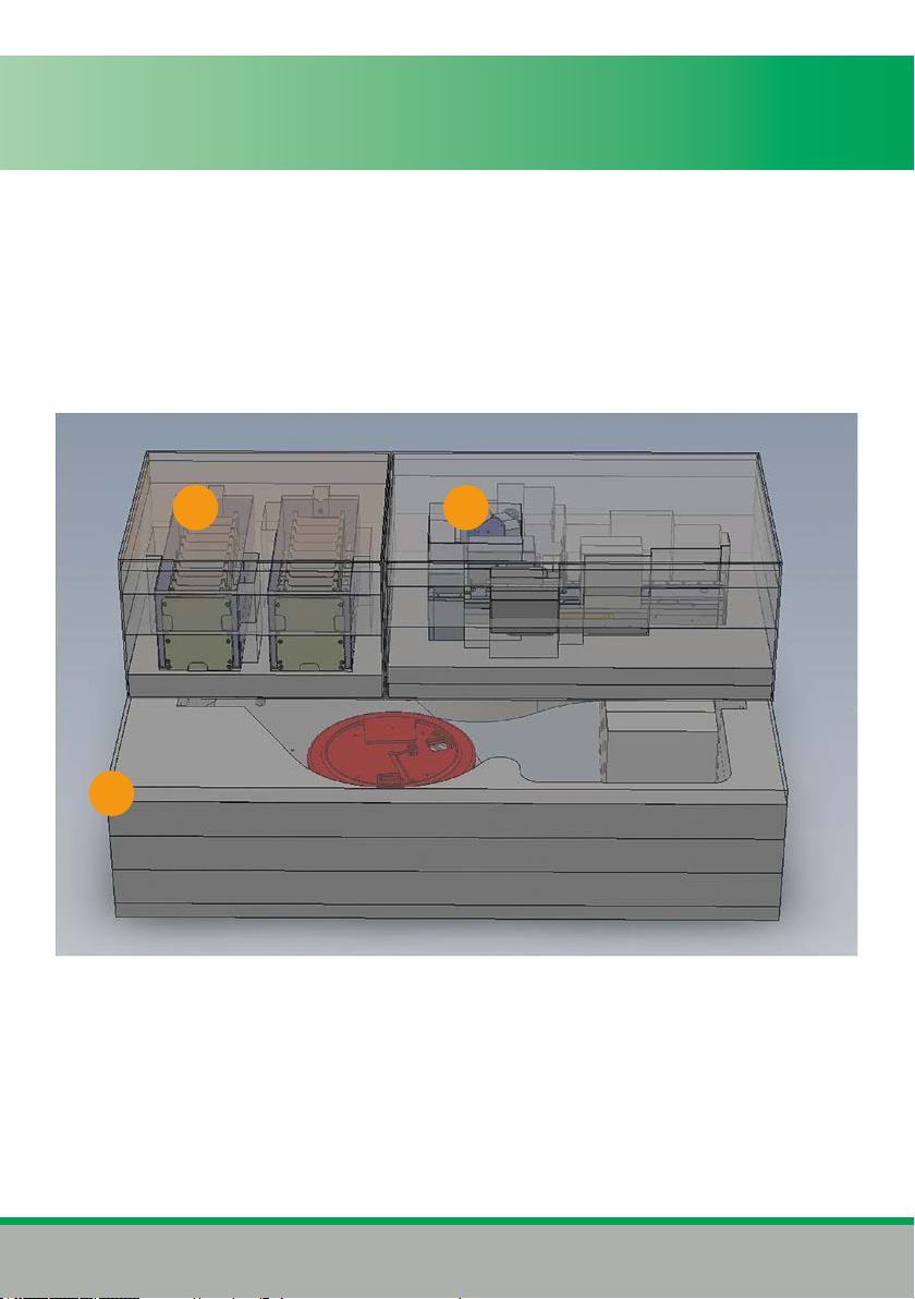
3.3 PACKING
ThePLW20issecurelyandsafelypackedin3sectionsinsidethebox.
Sectiononecontains2x10slothotels.
Section two contains the plate loader tower.
Section three contains the X-axis assembly and base kit.
2
3
1

PLW20 Manual V3.010
Section 4
IDENTIFYING YOUR SYSTEM
4.1 SYSTEM DIAGRAM
1
2
3
46
7
5
1) Z-Axisarm
2) BarcodeReader(optional)
3) Gripper
4) Y-axistower
5) Baseplate
6) HotelRack2
7) HotelRack1
8) Apartment10
9) Apartment1
10) Hotelrack
11) Z-Axislinearrail
12) Gripperarms
13) Barcodereader
8
9
10
11
13
12

More to PRIOR than meets the eye
www.prior.com 11
4.2 PLATE LOADER MOVEMENT AND AXIS IDENTIFICATION
PlateloadermovementisdenedasX,Y,Z,andG.Xaxisbeingtherotationalmovement
oftheplateloader.Yaxisrelatestotheupanddownmovementoftheloaderarm.Zaxis
Relatestotheextendandretractmovementoftheextensiononthegripperarm.Finally,G
axis movement relates to the opening and closing of the gripper jaws.
4.3 CONNECTION IDENTIFICATION
1) Mainsconnector
2) Fusehousings
3) USBconnector
4) On/oswitch
5) 4Waybindersocket
1 2 3 4
5

PLW20 Manual V3.012
Section 5
INSTALLATION
5.1- INSTALLING YOUR SYSTEM
RemoveX-axisassemblyfrompackagingcaseandplaceonsuitablebench.(Fig1).Note
positionoftheemergencystop(circled).
RemoveY-axistowerassemblyfrompackagingandlowerontox-axisassemblyasshown
(Fig2).Ensurematingfacesaredebrisfreeandalignedcorrectly.AlignDconnectoron
loaderarmwiththeDconnectorontheloaderbase.(Fig3).Onceinplaceensurethatthe
bottomofthetowerisushwiththebasebeforesecuringwiththefourM5screwsandthe
singleM3screw(Fig02&03).WithY-axistowerinstalled,removeantirotationshipping
screw(Fig02).
1

More to PRIOR than meets the eye
www.prior.com 13
Remove anti rotation
shipping screw
INSERT M3 x 6 socket pan
head screw to secure
INSERT M5 x 16 socket
button head screws into
each of four positions and
securermly.
M5mountingholesarecircledinorange,M3mountingholesingreen.
2
PLW20 Manual V3.014
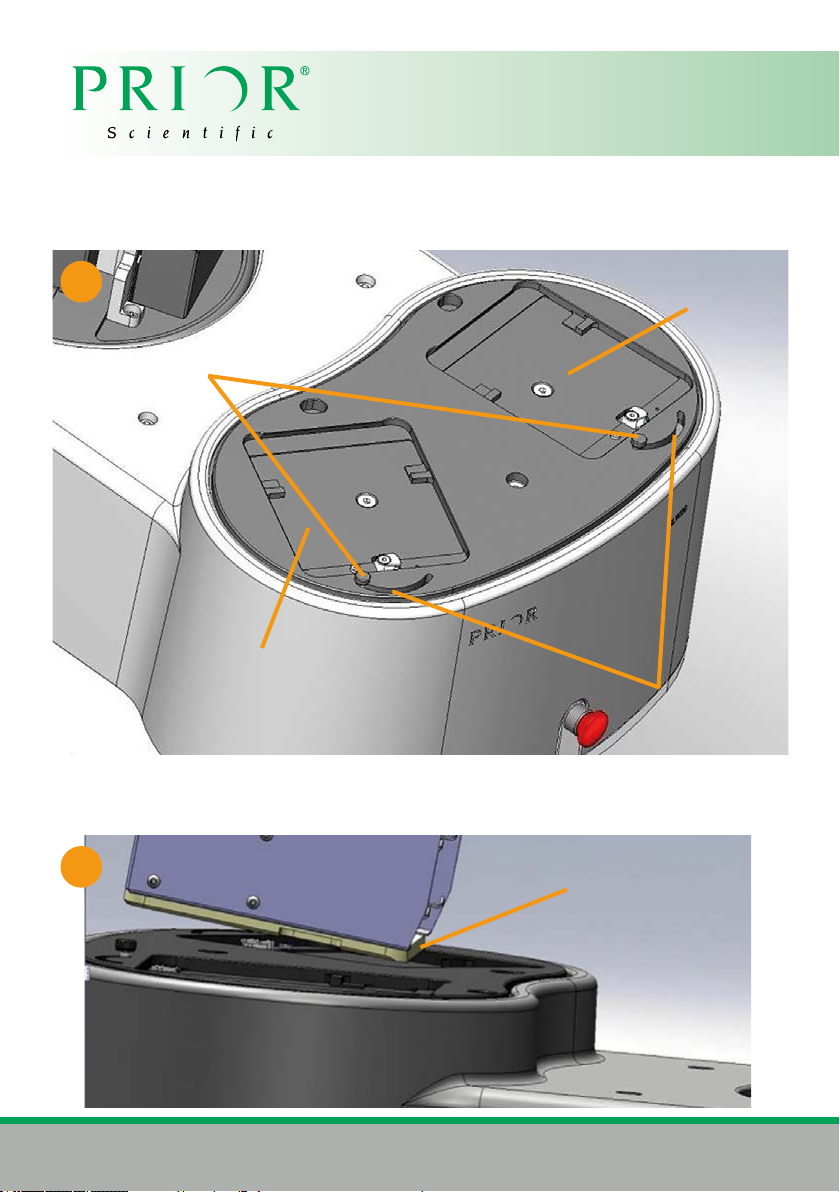
Removewellplatehotelsfrompackagingandtontoloaderplate.Ensurelockingclaspis
positionedasshownbelow(Fig04)
Locatedovetailonfrontofhotelundertheplatedovetailonloader,andlowerrearofhotel
downontoplate.(Fig05)
4
Hotel present switch
Well plate
hotel locking
clasp
Hotel 2 bay
Hotel 1 bay
Hotel Dovetail
5

More to PRIOR than meets the eye
www.prior.com 15
Withthehotelinpositionmoveclasptoright(Fig6)tosecurethehotelinplaceandactivate
‘hotelpresent’switch.Repeatforhotel2.
6

PLW20 Manual V3.016
5.2 INSTALLING THE STAGE ONTO THE MICROSCOPE
The Prior ProScan stage is supplied with the correct base plate to suit the microscope
specied
1. (Fig7.1)FixtheH4194mountingplateontothefrontmountingholesonthemicroscope
andxusingthecountersunkscrewsprovided(A).
2. (Fig7.2)Placethestageoverthemountingbracketandxtherearofthestageto
themicroscopeasillustrated.EnsurethecablecountingtheinserttothePLW20exits
towards the rear of the stage.
3. Viewingtheundersideofthestage,attachittothemountingplate,viathexingpoints
attheextremeendsofthemountingplate(B).
4. ConrmthattheProScancontrollerunitisswitchedobeforeconnectingthestageto
the controller with the cable provided.
5. The cable connections to the ProScan controller are located on the rear panel of the
control box
Beforemakinganyoftheseconnections,ensurethattheProScancontrollerisswitched
o.Eachconnectioniswelllabeledbutgreatcareshouldbetakennottotryandconnect
yourcomputer’sserialportcabletothe`Z’axisconnectoronthecontroller.TheRS232
connection from your computer should be made to the RS232-1 port on the controller. For
USB connection to your computer see separate section on this subject.
A A B
B
7.1

More to PRIOR than meets the eye
www.prior.com 17
7.2
Mounting Holes
CabletoPLW20
Stage Locking Clamp
Front of the Microscope
Rear of the Microscope

PLW20 Manual V3.018
Section 6
SETUP OF THE PLW20
6.1 SOFTWARE
BeforeworkingwiththePLW20youmustrstinstallPriorsoftwareonyourPC.VisitPrior
software download centre website and download either the 32bit software or 64bit software
depending on your Windows operating system. Make sure the software is version v8.4.35 or
above.
http://www.prior-scientic.co.uk/Customer-Support/Download-Centre/
32bitsoftwaredownloadforWindowXPandWindow7(v8.4.35):Demonstrationprograms
forProScan,OptiScan,SlideLoaderandPlateLoader;USBdriversandPCIcarddrivers.
Or
64bitsoftwaredownloadforWindowXPandWindow7(v8.4.35):Demonstrationprograms
forProScan,OptiScan,SlideLoaderandPlateLoader;USBdriversandPCIcarddrivers.
Afterinstallationofthesoftware,youcanlocatethe“WellPlateLoderdemo”programunder
thePriorScientic/VisualBasicfolderoftheWindowsstartmenu.
IfyouareusingWindows7plugintheUSBcabletothePLW20andthecomputer,and
poweronthePLW20.Thedeviceshouldbeautomaticallyrecognisedandtheappropriate
driversinstalled.ForotheroperatingsystemspleasecontactPriorScienticoryourlocal
dealer.
6.2 SOFTWARE SCREEN
More to PRIOR than meets the eye
www.prior.com 19
6.3 STARTING SETUP
Note:AredFastStopbuttoncanbefoundonthefrontofthePlateloader.Thiscanbeused
toinstantlycutthepowertotheloader,immediatelyhaltinganyarmmovements.Thisbutton
must be release before power can be returned to the loader.
It is important for the plate loader to initialize to known datum points before you can proceed
withthesetupprocedure.Thedatumpointsarethelimitswitcheswhichdenetheend
pointsofthetravelfortheX,Y,andZoftheloader.
Beforebeginningtheinitialisationprocedureremoveanyhotels(wellplatecassettes)from
the loader and make sure that nothing is in a position where the loader can collide with it.
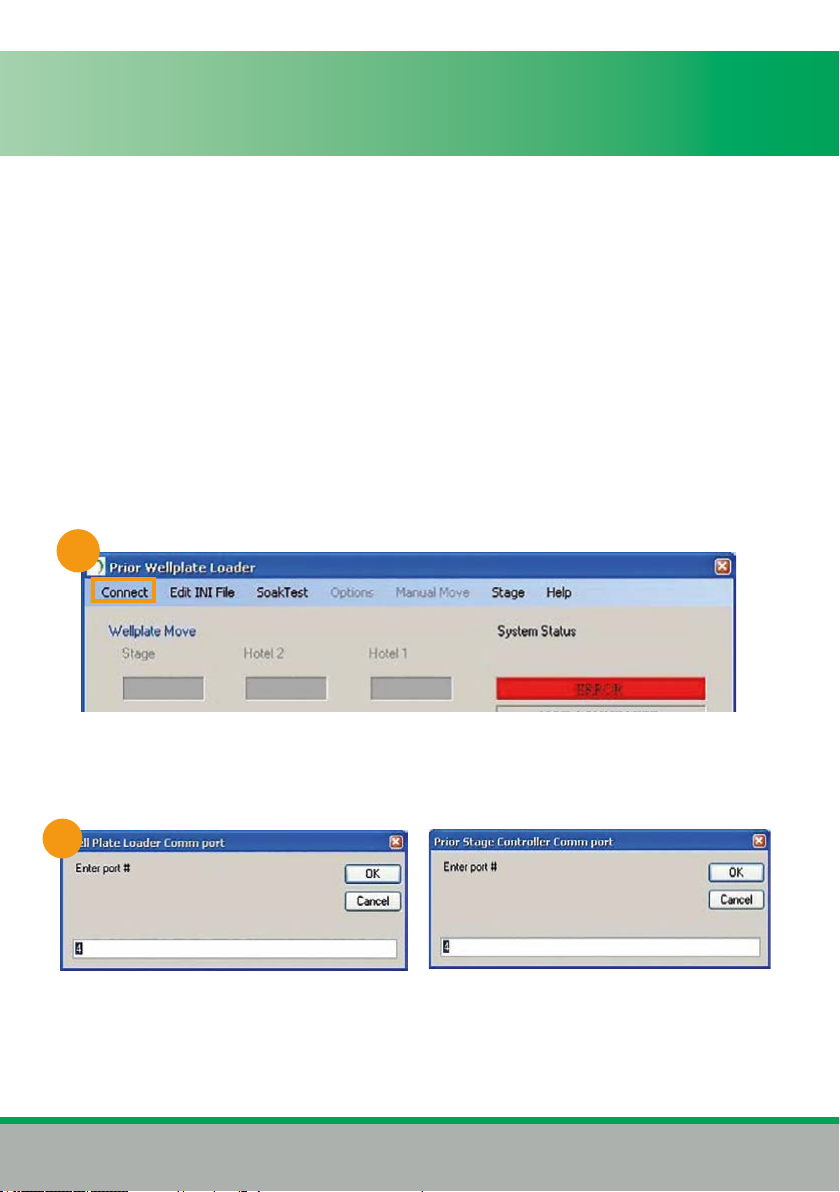
1. Switch on the Well Plate Loader.
2.OpenPriorWellPlateLoadersoftware.(Fig10)
3.Click“Connect”,onthemenubar.
4.Enterorconrmthe“WellPlateLoaderCommport”numberandthe“PriorStage
ControllerCommport”.(Fig11)TheportaddressisautomaticallyassignedbyWindowsbut
canbeconrmedthroughthesystemsDeviceManager.
10
11
PLW20 Manual V3.020
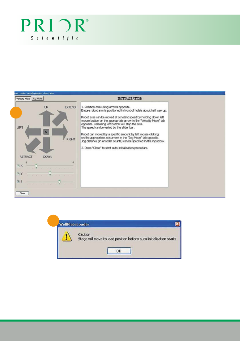
5.Themanualmoverscreenwillappear(Fig12),usethistomovetheloadertoaposition
clearofthestageandabouthalfwayuptheYaxis.
Ifawarningappearsindicatingthatawellplateisinthegripper,manuallyremovethis
wellplateandcontinue.UsetheGbuttoninthemanualmoverscreentoopenthegripper,
remember to place a hand under the well plate to catch it as the gripper arms open.
Closingthemanualmovescreenwillbringupthefollowingwindow(Fig13).
Click‘OK’tocontinue.ThestagewillthenmovetoitsLoadPositionandtheloaderwill
automatically perform initialisation. Once this is completed the setup procedure can begin.
12
13
Table of contents
Other Prior Scientific Laboratory Equipment manuals


Popular Laboratory Equipment manuals by other brands

Thermo Scientific
Thermo Scientific Thermo Scientific EASYpure RoDi operating manual

Grant-bio
Grant-bio PCV-6000 operating instructions

VWR
VWR PerfectBlue Twin S instruction manual

REPLIGEN
REPLIGEN XCell ATF Series user guide

Gilson
Gilson SS-15D operating manual

Kendro
Kendro Heraeus Biofuge haemo Instructions for use


Retsch
Retsch GRINDOMIX GM 200 operating instructions

Glas-Col
Glas-Col 099A RD7512 Operating and safety instructions

Izon
Izon AUTOMATIC FRACTION COLLECTOR V2 quick start guide

TPC
TPC H6000 user manual

Agilent Technologies
Agilent Technologies Medalist i1000 installation guide

Integra
Integra MEDIAJET operating instructions