Pro-face ST3200 Series User manual

1/34
Easy! Smooth!
ST3200 Series->GP4000M Series
Replacement Guidebook
3rd Edition Jan. 2019
Copyright © 2012.7 Digital Electronics Corporation. All Rights Reserved.
2/34
Preface
This guidebook introduces the procedures to replace a unit in ST3200 series with a
GP-4201TM unit.
Model in use
Model No.
Recommended Substitution
ST-3201A
AST3201-A1-D24
GP-4201TM
Safety Information
HAZARD OF OPERATOR INJURY, OR UNINTENDED EQUIPMENT DAMAGE
Before operating any of these products, be sure to read all related manuals thoroughly.
Failure to follow these instructions can result in death, serious injury or unintended equipment
damage.

3/34
Contents
PREFACE 2
SAFETY INFORMATION 2
HAZARD OF OPERATOR INJURY, OR UNINTENDED EQUIPMENT DAMAGE
2
CONTENTS 3
CHAPTER 1 SPECIFICATION COMPARISON 5
1.1 SPECIFICATIONS OF ST-3201A AND GP-4201TM 5
CHAPTER 2 COMPATIBILITY OF HARDWARE 7
2.1 LOCATIONS OF CONNECTORS 7
2.2 TOUCH PANEL SPECIFICATIONS 8
2.3 DISPLAY COLORS (FOR GP-3301L/3302B AND ST-3301B ONLY) 8
2.3.1 BLINK 8
2.3.2 DISPLAY COLORS 8
2.4 PANEL CUTOUT DIMENSIONS 8
2.5 EXTERNAL DIMENSIONS 9
2.6 TRANSFER CABLE 9
2.7 INTERFACE 10
2.7.1 SERIAL INTERFACE 10
2.7.2 CF CARD INTERFACE 10
2.8 CLOCK 10
2.9 PERIPHERAL UNITS AND OPTION UNITS 11
2.9.1 BARCODE READER CONNECTOIN 11
2.9.2 PRINTER CONNECTION 11
2.9.3 EXPANSION UNIT 11

4/34
2.9.4 ISOLATION UNIT 11
2.10 POWER CONSUMPTION 12
2.11 BACKUP MEMORY (SRAM) 12
2.12 ABOUT LADDER MONITOR 12
2.13 ABOUT PRO-SERVER 13
2.14 OTHER NOTES 13
CHAPTER 3 REPLACEMENT PROCEDURE 14
3.1 WORK FLOW 14
3.2 PREPARATION 15
3.3 RECEIVE SCREEN DATA FROM GP/ST3000 SERIES 16
3.4 CHANGE THE DISPLAY UNIT TYPE 19
3.5 TRANSFER SCREEN DATA TO GP-4201TM 21
3.6 DIFFERENCES OF SOFTWARE 25
CHAPTER 4 COMMUNICATION WITH DEVICE/PLC 26
4.1 DRIVERS 26
4.2 SHAPES OF COM PORTS 26
4.3 SIGNALS OF COM PORTS 27
4.3.1 DIFFERENCES OF COM1 SIGNALS 27
4.3.2 DIFFERENCE OF COM2 SIGNALS 29
4.4 MULTILINK CONNECTION 29
4.5 CABLE DIAGRAM AT THE TIME OF REPLACEMENT 30
CHAPTER 5 APPENDIX 31
5.1 WHEN THE DISPLAY UNIT TYPE CANNOT BE CHANGED, 31

5/34
Chapter 1 Specification Comparison
1.1 Specifications of ST-3201Aand GP-4201TM
ST-3201A
GP-4201TM
Display Type
Monochrome Amber/Red
LCD
NEW! TFT Color LCD
Display Colors, Levels
Monochrome, 8 levels
UP! 65,536 colors
Display Resolution
QVGA (320x240 pixels)
Panle Cutout
Dimensions (mm)
W118.5xH92.5mm
NEW! φ22mm
->See 2.4
External
Dimensions
(mm)
W130xH104xD40mm
NEW!
W118xH98.15xD56.3mm
*The rear module is included.
->See 2.5
Touch Panel Type
Resistive film (Analog) ->See 2.2
Memory
Application
6MB
UP! 8MB
Backup
320KB
128KB ->See 2.11
Backup Battery
Secondary Battery
(Rechargeable Lithium
battery)
-
Rated Input Voltage
DC 24V
Serial
I/F
COM1
D-Sub 9 pin (plug)
RS-232C
D-Sub 9 pin (plug)
RS-232C/422/485
COM2
D-Sub 9 pin (plug)
RS-422/485
-
->See 2.7.1 / Chapter 4


7/34
Chapter 2 Compatibility of Hardware
2.1 Locations of connectors
Connector locations on ST3000 series and GP-4201TM are as follows:
ST-3201A
GP-4201TM
Interface names
ST-3201A
GP-4201TM
1
Power Connector
2
Serial Interface (COM1)
3
Serial Interface (COM2)
-
4
-
Ethernet Interface
5
USB Interface (Type A)
6
-
USB Interface (Type miniB)
8/34
2.2 Touch panel Specifications
GP-4201TM adopts Analog resistive film type.
Because of it, GP-4201TM doesn’t support 2-point touch input (touching 2 points on the
screen at the same time). Even if two different points are touched at the same time,
that’s recognized as touch input on the middle coordinates between those two points.
2.3 Display Colors (for GP-3301L/3302B and ST-3301B only)
2.3.1 Blink
GP-4201TM does not have a Blink feature.
Replace ST-3201A with GP-4201TW if feature is nedded.
2.3.2 Display Colors
ST-3201A has monochrome LCD, but GP-4201TM has TFT color LCD. After replacement,
the black and white display changes to the color display.
When data of a monochrome model are converted to a color model with GP-Pro EX, the
data may be displayed in colors except black and white depending on a setting of
GP-Pro EX. After conversion, please confirm the display colors of drawing or parts on
screens just in case.
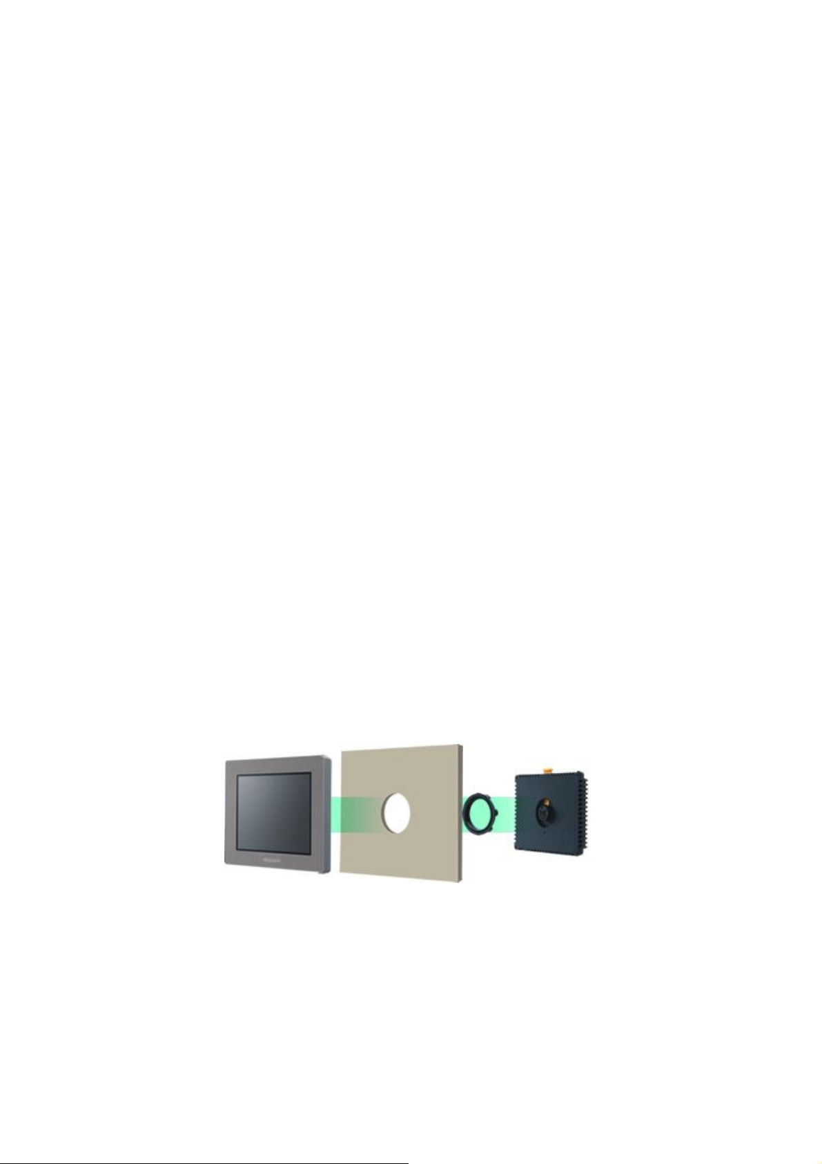
2.4 Panel cutout dimensions
The panel cutout of GP-4201TM is a φ22-mm circular hole. The panel cutout shape and
dimensions of GP-4201TM are different from those of ST3000 series.

9/34
2.5 External Dimensions
For GP-4201TM, the front face display module (display part) and the back face main
module are separated. Compared with ST3000 series, the tickness of the part
appearing on the installation panel differs.
2.6 Transfer cable
To transfer screen data to GP-4201TM, use a USB transfer cable or Ethernet. Use a USB
data-transfer cable (model: ZC9USCBMB1) or a commercial USB cable (USB A/mini-B).
Please note that the cables (CA3-USBCB-01) for ST3000 series cannot be used for
GP-4201TM.
ST-3201A
GP-4201TM
A
(the thickness of
the front bezel)
5mm
16.2mm
B
(the depth of the
back face)
35mm
40.1mm
10/34
2.7 Interface
2.7.1 Serial Interface
For the COM ports of ST3000 series and GP-4201TM, the signal of the serial port is
different. To know the details about them, see [4.2 Shapes of COM ports] and [4.3
Signals of COM ports].
Because of it, the existing PLC connection cables cannot be used as they are. If you
use the existing connection cables, see [4.5 Cable Diagram at the time of
replacemet].
When the both COM1 and COM2 ports on ST3000 series have setting, devices can be
connected to the COM1 port only after replacement with GP-4201TM.
- When the COM1 port is used for RS-232C connection and the COM2 port for
RS-422/485 connection:
Replace with GP-4201TW instead of GP-4201TM.
- When the both COM1 and COM2 ports are used for RS-422/485 connection:
Please contact our sales office in your region.
(http://www.pro-face.com/customer/contact.html)
2.7.2 CF Card Interface
GP-4201TM is not equipped with a CF card slot. You can use an USB storage device
instead of a CF card but GP-4201TM supports the function of saving sampled data in
CSV only (GP-Pro EX Ver. 3.01 or later is required).
You can use the storage devices below instead after replacement:
GP-4301T
SD card
GP-4301TW
USB storage device
2.8 Clock
There’s no battery in GP-4201TM. When the GP’s power is turned OFF, the clock data
is reset. Using the Clock Update Settings of GP-Pro EX allows you to take in the clock
data of the connected device. For details, refer to 5.2 Adjusting the Time in the
GP-Pro EX Reference Manual.

11/34
2.9 Peripheral units and option units
2.9.1 Barcode reader connectoin
GP-4201TM allows you to connect a barcode reader on its USB interface (Type A) in
the same as ST3000 series.
For the models GP-4201TM supports, see [OtasukePro!]
(http://www.pro-face.com/otasuke/qa/3000/0056_connect_e.html).H
And if you connect a barcode reader to GP-4201TM, be sure to supply power to the
barcode reader from an external power source (such as a USB hub supporting
self-power supply). When no power is supplied from an external power source, if the
barcode reader consumes more electricity than expected, operation of GP-4201TM
will become unstable and reset may be activated.
2.9.2 Printer connection
GP-4201TM does not support printer connection. A printer for ST3000 series cannot
be used.
2.9.3 Expansion Unit
GP-4201TM is not equipped with an expansion bus unit. The expansion units (such
as CC-LINK) used for ST3000 series cannot be used.
2.9.4 Isolation Unit
The isolation unit for ST3000 series (CA3-ISO232-01, CA3-ISO485-01) cannot be
used for GP-4201TM.

12/34
2.10 Power Consumption
The power consumption of ST3000 series is different from that of GP-4201TM.
For the detailed electric specifications, see the hardware manual.
2.11 Backup Memory (SRAM)
GP-4201TM does not have SRAM, but uses a part of application memory as a backup
area. Data in the backup area is retained even after power off or reset of GP-4201TM in
the same way as SRAM. The functions possible for backup on GP-4201TM are as
follows:
- Alarm History (Up to 768)
- Recipe (Filing data)
- Brightness/Contrast values
* For the functions above, data is saved in the backup area at the time of “Save”.
* Sampling and clock data is not backed up. If you need these functions, replace
ST3000 series with GP-4201TW (SRAM size: 128KB) or GP-4201T (SRAM size:
320KB) instead.
2.12 About Ladder Monitor
PLC Lader monitor tool cannot be used for SP5000 series.
ST-3201A
GP-4201TM
13W or less
6.5W or less

13/34
2.13 About Pro-Server
If the Pro-Server EX is used, please use Ver.1.32 or later. For details of the installation,
refer to the http://www.pro-face.com/otasuke/download/update/server_ex/.
2.14 Other Notes
Do not expose GP4000M series to direct sunlight.
Do not use GP4000M series outdoors.
Do not turn on GP4000M series if condensation has occurred inside the device.
When you are continuously using GP4000M series without oxygen, the
brightness might decrease. Please ventilate the control panel periodically.
14/34
Chapter 3 Replacement Procedure
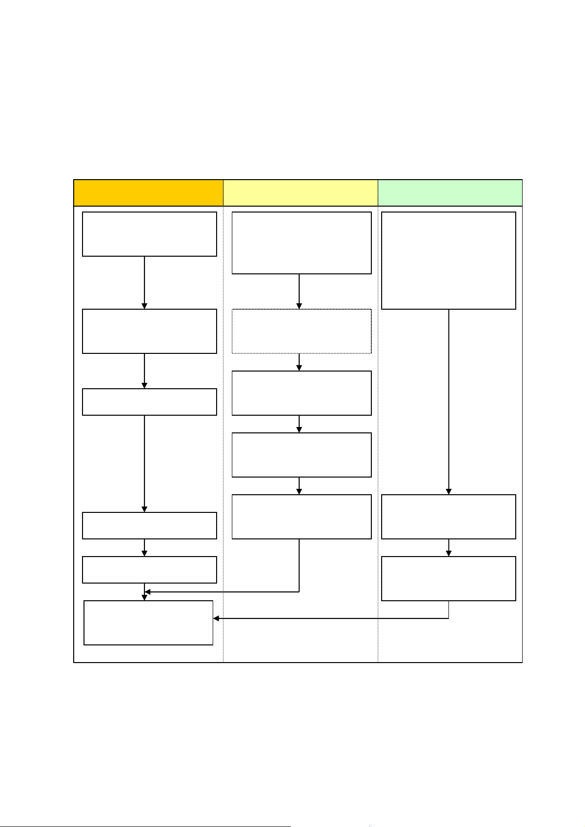
3.1 Work Flow
Receive screen data from
ST3000 series *1
Change the received data
on GP-Pro EX.
Check and modify the data
on GP-Pro EX.
Transfer the screen data to
GP-4201TM.
Connect GP-4201TM and
the PLC with a cable.
Start connection and check
the communication.
Remove ST3000 series.
Connect the power cord.
Check the performance
and start operation.
Installation
Screen
Communication
Install GP-4201TM.
Check the compatibility of
hardware in Chapter 2.
Check the connection
between GP-4201TM and a
PLC in the GP-Pro EX
Device/PLC Connection
Manual.
Check the restrictions for
GP-4201TM with GP-Pro EX
Reference Manual.
*1: This step is required if screen data is saved only in the display unit, not in any other device.
Process the panel.

15/34
3.2 Preparation
Requirements for
receiving screen data
from ST3000 series
*1
PC in which GP-Pro EX Transfer Tool is installed *2
A USB data-transfer cable (model: CA3-USBCB-01)
*ST3000 series also allows you to transfer screen data with a
CF card/USB flash drive, or Ethernet.
Requirements for
converting screen
data of ST3000
series and
transferring them to
GP-4201TM
PC in which GP-Pro EX Ver.2.71 or later is installed.
A USB datda-transfer cable (model: ZC9USCBMB1) or
A commercial USB cable (USB A/mini-B)
* GP-4201TM also allows you to transfer screen data via USB
flash drive or on Ethernet.
*1: This step is required if screen data is saved only in the display unit, not in any other device
*2: The software version must be the same as or higher than the version that you used when creating screen
data for ST3000 series.
We recommend you upgrade to the latest version if you don’t know the version you use. Upgrade it on our
website OtasukePro! (http://www.pro-face.com/otasuke/).
16/34
3.3 Receive screen data from GP/ST3000 series
This section explains, as an example, how to receive screen data from ST3000 series
using a transfer cable, CA3-USBCB-01. If you have backed up screen data, this step is
unnecessary; skip to the next section [3.4 Change the Display Unit type].
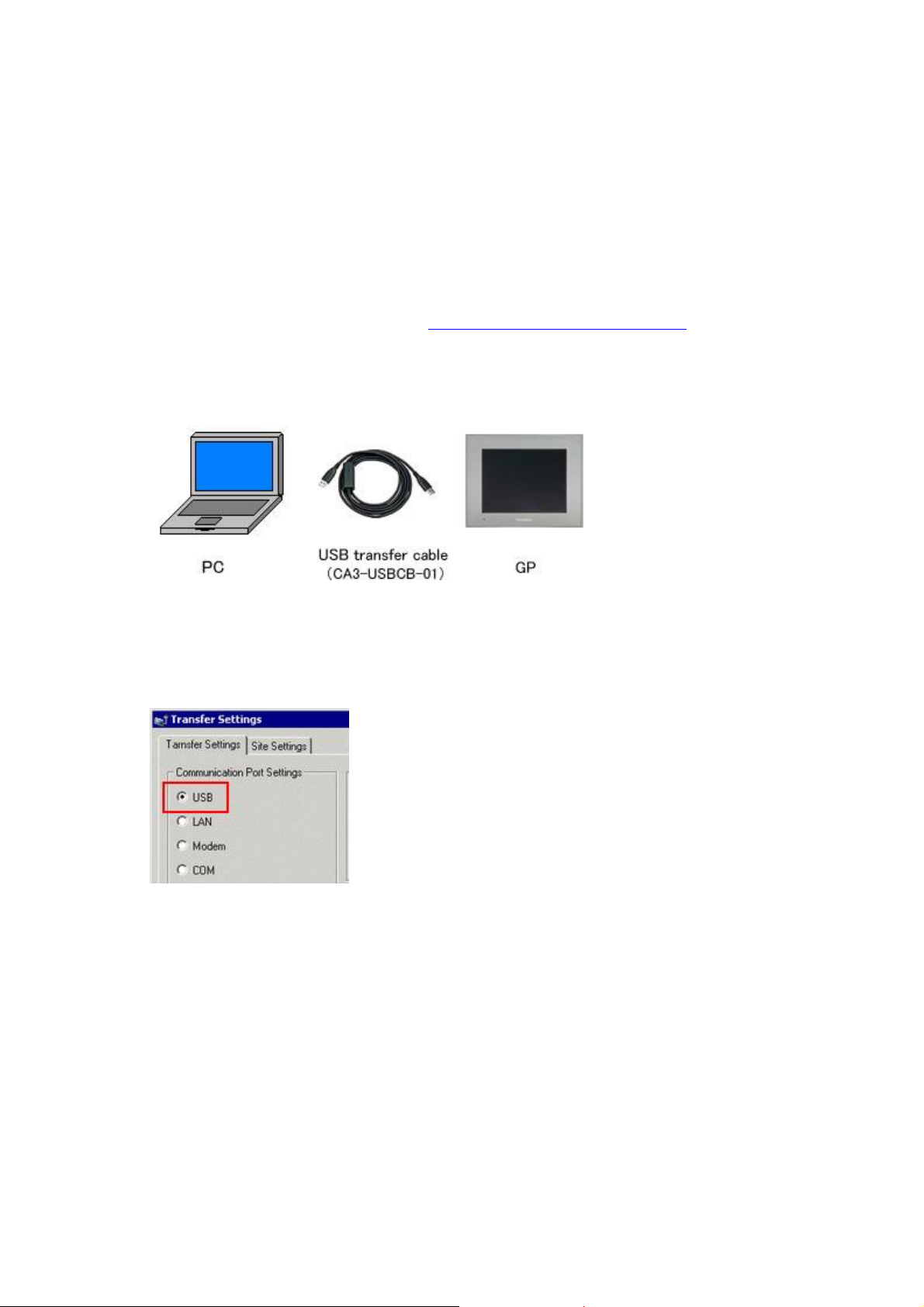
(1) Connect a USB transfer cable to a unit of ST3000 series.
(2) Make sure that the [Device] in the “Transfer Settings Information” is set to [USB].
If not, click the [Transfer Setting] button to open the “Transfer Setting” dialog box.
Select [USB] in the Communication Port Settings field and click [OK].
17/34
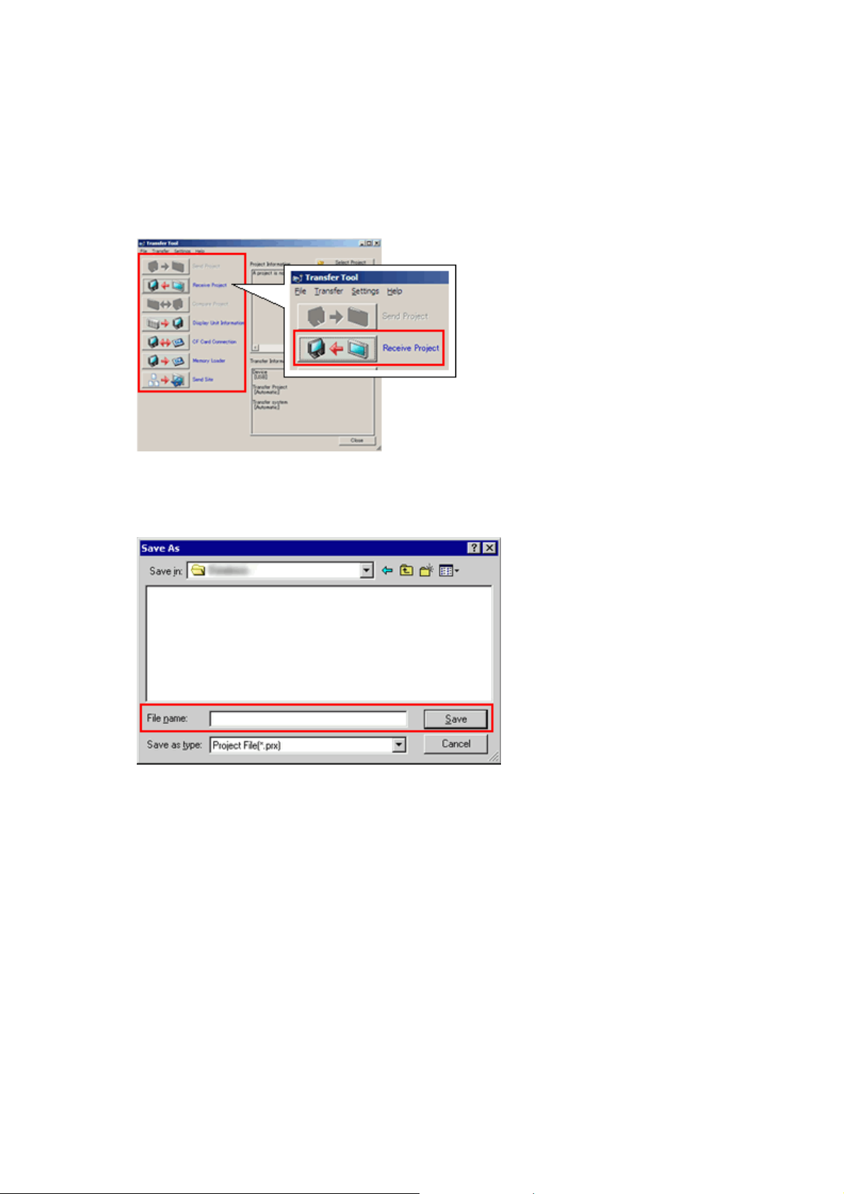
(3) Start GP-Pro EX Transfer Tool and click the [Receive Project] button.
(4) Click [Receive Project], and the following dialog box will appear. Specify a place to
save the received data in and a project file name, and then click [Save] to start
transfer.

18/34
The following dialog box appears during transfer and you can check the
communication status. (The display unit enters the Transferring mode and
communication with the device such as a PLC is terminated.)
(5) When transfer is completed, the status displayed in the dialog box will change from
[Transferring] to [Complete Transfer]. Click [Close] to close the dialog box.
(6) Close the Transfer Tool.
Display Screen
19/34
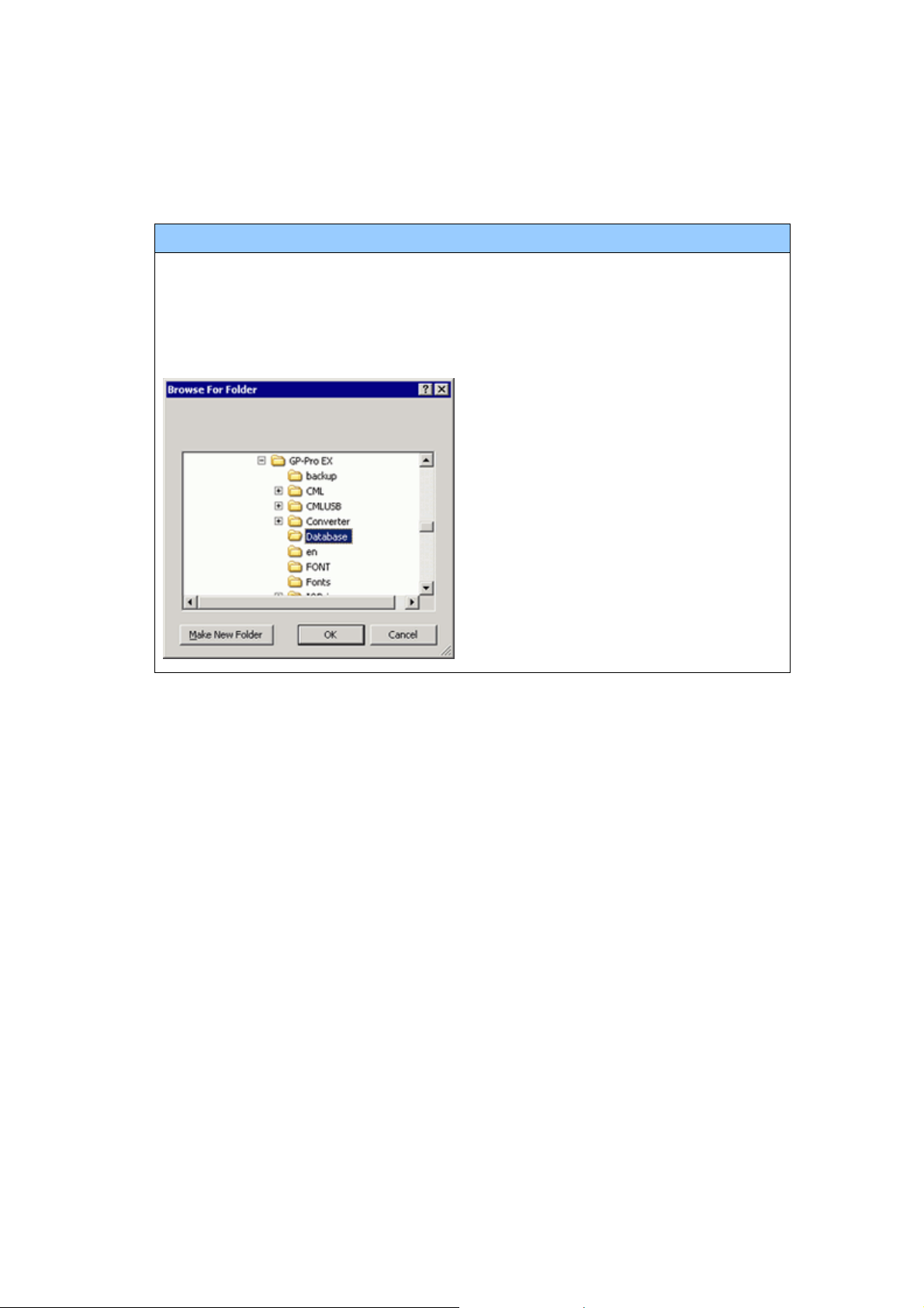
NOTE
If you receive the project files that use CF card data such as Recipe Function
(CSV data), the following dialog box will appear during transfer. Specify a place
to save the CF card data in. Click [OK], and the [Receive Project] dialog box will
return and transfer will be completed.
3.4 Change the Display Unit type
Open the received project file (*.prx) of ST3000 series with GP-Pro EX and change the
display unit type to GP-4201TM.
(1) Open the received project file (*.prx) with GP-Pro EX.
(2) Change the Display Unit type to GP-4201TM in [Display] on [System Settings] of
GP-Pro EX.

20/34
NOTE
・If you change the Display Unit type, the parts or the function settings that do not
support GP-4201TM are deleted, initialized, or changed.
For the functions GP-4201TM doesn’t support and the important notes, see [3.6
Differences of software].
・Depending on a setting of the project file, the message as shown below appears,
the Display Unit may not change to GP-4201TM.
When the message appears, check the cause and the solution in [5.1 When the
Display Unit cannot be changed] and then change the Display Unit again.
Other manuals for ST3200 Series
1
This manual suits for next models
3
Table of contents
Other Pro-face Recording Equipment manuals

Pro-face
Pro-face GP-4114T User manual

Pro-face
Pro-face LT-4201TM User manual

Pro-face
Pro-face AGP-3300 Series User manual

Pro-face
Pro-face GP-2401T User manual

Pro-face
Pro-face ST3200 Series User manual

Pro-face
Pro-face ST3000 Series User manual

Pro-face
Pro-face GP-4100 series User manual

Pro-face
Pro-face GP-4100 series User manual

Pro-face
Pro-face GP2000H Series User manual

Pro-face
Pro-face GP3000 Series User manual


