Pro-face LT-4201TM User manual

LT-4201TM/4301TM
Installation Guide

2
English
The information provided in this documentation contains general descriptions and/or
technical characteristics of the performance of the products contained herein. This
documentation is not intended as a substitute for and is not to be used for determining
suitability or reliability of these products for specific user applications. It is the duty of any
such user or integrator to perform the appropriate and complete risk analysis, evaluation
and testing of the products with respect to the relevant specific application or use thereof.
Neither Pro-face nor any of its affiliates or subsidiaries shall be responsible or liable for
misuse of the information that is contained herein. If you have any suggestions for
improvements or amendments or have found errors in this publication, please notify us.
No part of this document may be reproduced in any form or by any means, electronic or
mechanical, including photocopying, without express written permission of Pro-face.
All pertinent state, regional, and local safety regulations must be observed when installing
and using this product. For reasons of safety and to help ensure compliance with
documented system data, only the manufacturer should perform repairs to components.
When devices are used for applications with technical safety requirements, the relevant
instructions must be followed.
Failure to use Pro-face software or approved software with our hardware products may
result in injury, harm, or improper operating results.
Failure to observe this information can result in injury or equipment damage.
Copyright © 2016.06 Digital Electronics Corporation. All Rights Reserved.

3
LT-4201TM/4301TM Installation Guide
English
Safety Information
Important Information
NOTICE
Read these instructions carefully, and look at the equipment to become familiar with the
device before trying to install, operate, or maintain it. The following special messages may
appear throughout this documentation or on the equipment to warn of potential hazards or
to call attention to information that clarifies or simplifies a procedure.

4
English
PLEASE NOTE
Electrical equipment should be installed, operated, serviced, and maintained only by
qualified personnel. No responsibility is assumed by Pro-face for any consequences arising
out of the use of this material.
A qualified person is one who has skills and knowledge related to the construction and
operation of electrical equipment and its installation, and has received safety training to
recognize and avoid the hazards involved.

5
LT-4201TM/4301TM Installation Guide
English
About the Book
At a Glance
Thank you for purchasing Pro-face's LT4000 Series Graphic Logic Controller Interface
(Hereafter referred to as the "LT").
Document Scope
This guide describes how to install the LT-4201TM/4301TM. For more detailed information,
refer to the manuals indicated below.
Global Code
A global code is assigned to every Pro-face product as a universal model number.
For more information on product models and their matching global codes, please refer to
the following URL:
http://www.pro-face.com/trans/en/manual/1003.html
Validity Note
This documentation is valid for GP-Pro EX V4.0 or later.
The characteristics presented in this manual should be the same as those that appear
online. In line with our policy of constant improvement we may revise content over time to
improve clarity and accuracy. In the event that you see a difference between the manual
and online information, use the online information as your reference.
Related Documents
You can download these technical publications and other technical information from our
support site at http://www.pro-face.com/trans/en/manual/1001.html.
Title of Documentation Reference Number
GP-Pro EX Reference Manual
Maintenance/Troubleshooting Guide
• Troubleshooting
Help for solving problems.
• Maintenance
Details on the LT unit’s Offline Mode
GP-Pro EX Device/PLC Connection Manual System configuration of connected
devices (PLCs and other devices),
communication settings examples,
connection wiring diagram, and other
details.
LT-4201TM/4301TM Hardware Manual Specifications, dimensions,
accessories, system design,
standards, and other details.

6
English
Product Related Information
This equipment has been designed to operate outside of any hazardous location. Only
install this equipment in zones known to be free of a hazardous atmosphere.
DANGER
HAZARD OF ELECTRIC SHOCK, EXPLOSION OR ARC FLASH
Disconnect all power from all equipment including connected devices prior to
removing any covers or doors, or installing or removing any accessories, hardware,
cables, or wires except under the specific conditions specified in the appropriate
hardware guide for this equipment.
Always use a properly rated voltage sensing device to confirm the power is off where
and when indicated.
Replace and secure all covers, accessories, hardware, cables, and wires and confirm
that a proper ground connection exists before applying power to the unit.
Use only the specified voltage when operating this equipment and any associated
products.
Failure to follow these instructions will result in death or serious injury.
DANGER
POTENTIAL FOR EXPLOSION
Install and use this equipment in non-hazardous locations only.
Failure to follow these instructions will result in death or serious injury.

LT-4201TM/4301TM Installation Guide
7
English
1 For additional information, refer to NEMA ICS 1.1 (latest edition), "Safety Guidelines for
the Application, Installation, and Maintenance of Solid State Control" and to NEMA ICS 7.1
(latest edition), "Safety Standards for Construction and Guide for Selection, Installation and
Operation of Adjustable-Speed Drive Systems" or their equivalent governing your particular
location.
WARNING
LOSS OF CONTROL
Consider the potential failure modes of control paths in the machine control system
design, such as:
The possibility of backlight failure,
Unanticipated link transmission delays or failures,
The operator being unable to control the machine,
The operator making errors in the control of the machine.
Design outside the LT operations such as emergency stop, safety circuits, interlocks
that operate with opposing actions such as clockwise/counterclockwise rotation, and
circuits that prevent machine damage with positioning limits on top, bottom, and
movement.
For important operations handled by switches, design your system to use a separate
hardware device. This is to reduce the occurrence of incorrect outputs or
malfunctions.
Observe all accident prevention regulations and local safety guidelines.1
Test individually and thoroughly each implementation of the equipment for correct
operation before service.
Failure to follow these instructions can result in death, serious injury, or equipment
damage.
8
English

9
LT-4201TM/4301TM Installation Guide
English
LT-4201TM/4301TM In stallation Guide
LT-4201TM/4301TM
LT-4201TM/4301TM of Panel s
LT-4201TM/4301TM of Panels
LT Range
Thank you for purchasing Pro-face's LT4000 Series unit (hereafter referred to as the “LT”):
NOTE: Fast Input and Fast Output are generic terms for the following functions:
Fast Input: High-speed Counter Input and Pulse Catch Input.
Fast Output: Pulse Output, PWM Output and High-speed Counter Synchronize Output.
Series Model Names Models Digital
Input
Digital
Output
Analog Input Analog
Output
Screen
Size
LT4000
Series
LT-4201TM
(Modular Type
DIO)
PFXLM4201TADDC
PFXLM4201TADDK
20 Points
Standard
Input
(2 Points
for Fast
Input)
10 Points
Standard
Output
and
2Points
Fast
Output
None None 3.5 in.
LT-4301TM
(Modular Type
DIO)
PFXLM4301TADDC
PFXLM4301TADDK
5.7 in.
LT-4000M
(Modular Type
DIO)
PFXLM4B01DDC
PFXLM4B01DDK
None
LT-4201TM
(Modular Type
Analog)
PFXLM4201TADAC
PFXLM4201TADAK
12 Points
Standard
Input
(2 Points
for Fast
Input)
6Points
Standard
Output
and
2Points
Fast
Output
2 ch analog
inputs (13-bit)
and 2 ch
analog inputs
(16-bit) for
Thermocouple
2ch
analog
outputs
(12-bit)
3.5 in.
LT-4301TM
(Modular Type
Analog)
PFXLM4301TADAC
PFXLM4301TADAK
5.7 in.
LT-4000M
(Modular Type
Analog)
PFXLM4B01DAC
PFXLM4B01DAK
None
3.5 inch
display
module
PFXXM4200TP None 3.5 in.
5.7 inch
display
module
PFXXM4300TP None 5.7 in.

LT-4201TM/4301TM
10
English
Display Module/Rear Module Separation Cable Range
Agency Certifications for LT Unit
For information on Standards and Regulations, such as certified models and certificates,
see the marking on the product or the following link:
http://www.pro-face.com/trans/en/manual/1002.html
LT unit is manufactured in accordance with UL 508 and CSA C22.2 n°142 for industrial
control equipment.
For use on a flat surface of a Type 1, Type 4X (indoor use only) enclosure.
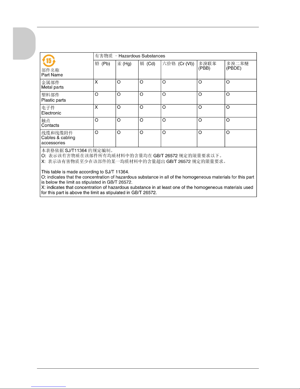
Hazardous Substances
This product is a device for use in factory systems. When using this product in a system,
the system should comply with the following standards in regards to the installation
environment and handling:
WEEE, Directive 2012/19/EU
RoHS, Directives 2011/65/EU
RoHS China, Standard SJ/T 11364-2014
REACH regulation EC 1907/2006
CE Markings
This product conforms to the necessary requirements of the following Directives for
applying the CE label:
2006/95/EC Low Voltage Directive
2004/108/EC EMC Directive
This conformity is based on compliance with IEC61131-2.
Reference Cable Length
PFXZXMADSM31 3 m (9.84 ft.)
PFXZXMADSM51 5 m (14.40 ft.)
NOTE: The outer diameter of the cable is 8 mm (0.13 in.). To assemble this product, you need
20 mm (0.78 in.) more space to bend the cable in the end of the rubber.

LT-4201TM/4301TM Installation Guide
11
English
Interfaces are: COM1, Ethernet, USB1 and USB2.
CAUTION
ENVIRONMENTAL HAZARDS TO THE EQUIPMENT
Allow the device to reach the surrounding air temperature, not exceeding 50 °C
(122 °F), before turning the device on.
Do not turn on the device if condensation has occurred inside the device. After it is
completely dry again, the device may be turned on.
Do not expose the device to direct sunlight.
Do not obstruct the vents in the device casing.
Remove any dust from the device before turning it on.
Ensure that the cable installation fasteners are not damaged. Replace them, if
necessary.
Mount the device into an enclosure that meets the IP65 level of protection.
Failure to follow these instructions can result in injury or equipment damage.
WARNING
RISK OF EXPLOSION IN HAZARDOUS LOCATIONS
Verify that the power, input, and output (I/O) wiring are in accordance with Class I,
Division 2 wiring methods.
Do not substitute components that may impair compliance to Class I, Division 2.
Do not connect or disconnect equipment unless power has been switched off or the
area is known to be non-hazardous.
Securely lock externally connected units and each interface before turning on the
power supply.
Do not, connect, or disconnect USB cable unless area is known to be non-hazardous.
Potential electrostatic charging hazard: wipe the front panel of the terminal with a
damp cloth before turning ON.
Failure to follow these instructions can result in death, serious injury, or equipment
damage.
WARNING
RISK OF EXPLOSION IN HAZARDOUS LOCATIONS
Do not disconnect while circuit is live.
Potential electrostatic charging hazard: wipe the front panel of the terminal with a
damp cloth before turning ON.
Failure to follow these instructions can result in death, serious injury, or equipment
damage.

LT-4201TM/4301TM
12
English
Package Contents
Verify that all items shown in the figure are present in your package:
Legend Description Package Type
LT Unit Display Module Rear Module
1 Display module Yes Yes No
2 Rear module Yes No Yes
3 Display installation nut
(attached to the display
module)
Yes Yes No
4 Anti-rotation tee Yes Yes No
5 Socket wrench Yes No No
6 USB clamp type A Yes No Yes
7 DC power supply connector Yes No Yes
8 I/O connector 15-pin 2 No 2
9 I/O connector 6-pin 2 No 2
10 LT-4201TM/4301TM
Installation Guide
Yes No Yes
11 Warning / Caution
information
Yes

LT-4201TM/4301TM Installation Guide
13
English
Handling the LCD
If the Panel is damaged and any liquid comes in contact with your skin, immediately rinse
the area with running water for at least 15 min.
If the liquid gets in your eyes, immediately rinse your eyes with running water for at least
15 minutes and consult a doctor.
Product Label Sticker
You can identify the product version (PV) and the revision level (RL) from the product label
on the panel.
The following diagram is a representation of a typical label:
LT4200/4300 Series model which unit's version number (PV ) is 02 or later can also be used
as Rear Module.
CAUTION
SERIOUS EYE AND SKIN INJURY
The liquid present in the LCD contains an irritant:
Avoid direct skin contact with the liquid.
Wear gloves when you handle a broken or leaking unit.
Do not use sharp objects or tools in the vicinity of the LCD touch panel.
Handle the Panel carefully to prevent puncture, bursting, or cracking of the Panel
material.
Failure to follow these instructions can result in injury or equipment damage.
LT-4201TM/4301TM
14
English
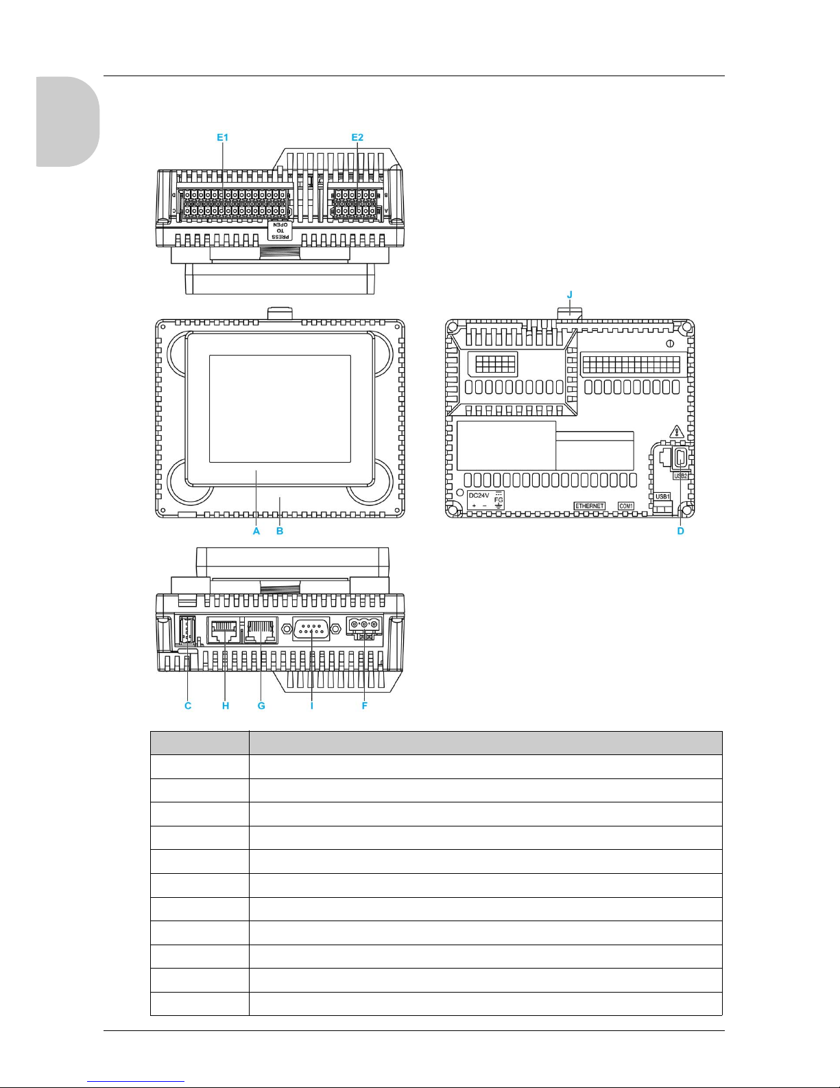
LT-4201TM/4301TM and Rear Module Parts Identification:
Part Description
A Display module
B Rear module
C USB (type A) interface connector (USB1)
D USB (mini B) interface connector (USB2)
E1 I/O terminal block 1
E2 I/O terminal block 2
F DC power supply connector
G Ethernet interface
H Serial link (RS-232C/485)
I CANopen interface
J Yellow button lock
15
LT-4201TM/4301TM Installation Guide
English
LT-4201TM/4301TM In stallation Guide
Installation
Installation
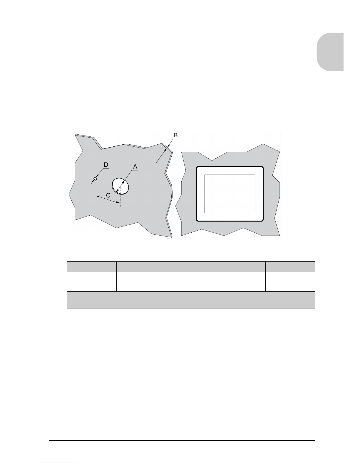
Inserting the Display Module with an Anti-Rotation Tee
Create a panel cut-out and insert the display module into the panel from the front. The figure
shows the panel cut-out:
Dimensions
NOTE: The display module supports a rotating torque of 6 N•m (53.10 lb-in).
Without the tee option, the display module supports a rotating torque of 2.5 N•m (22.12 lb-
in).
AB (1) B (2) C D
22.500/-0.30 mm
(0.880/-0.01 in.)
1.5...6 mm
(0.06...0.23 in.)
3...6 mm
(0.11...0.23 in.)
300/-0.20 mm
(1.180/-0.0007 in.)
40/-0.20 mm
(0.150/-0.007 in.)
(1) Steel sheet
(2) Glass fiber reinforced plastics (minimum GF30)

16
English
Installing the LT Display
The figure shows the assembly:
(1) Display module
(2) Panel
(3) Display installation nut
(4) Anti-rotation tee
Installing the LT Display Module with Spacer
The spacer supplied in the accessory kit PFXZGMAK1 (sold separately), allows mounting
the product on a:
steel sheet support with a thickness between 1 and 1.5 mm (0.039 in. and 0.059 in.)
plastic support with a thickness between 1 and 3 mm (0.039 in. and 0.118 in.)
glass fiber reinforced plastic with a thickness between 2 and 3 mm (0.078 in. and
0.118 in.)

LT-4201TM/4301TM Installation Guide
17
English
The figure shows the assembly with the Panel spacer:
(1) Display module
(2) Panel
(3) Spacer
(4) Display installation nut
(5) Anti-rotation tee
Installation of the LT Unit
In order to correctly run an application on the LT, both the display module and the rear
module must be connected.
WARNING
EXPLOSION HAZARD
Do not connect or disconnect while circuit is live.
Potential electrostatic charging hazard: wipe the front panel of the terminal with a
damp cloth before turning ON.
Refer to Hardware Manual for instructions
Failure to follow these instructions can result in death, serious injury, or equipment
damage.

18
English
If you power up the rear module without connecting the display module, the logic controller
does not start and all outputs remain in the initial state. The power must be off when you
connect the 2 modules.
There are 2 ways to install the LT.
Installing the LT on the panel:
Installing the rear module on a DIN rail with a display module/rear module separation
cable:

LT-4201TM/4301TM Installation Guide
19
English
Setup Procedure
Mount the unit in an enclosure that provides a clean, dry, robust, and controlled
environment (IP65 enclosure or UL508 4x if indoors).
Before installing the LT Unit verify that:
The installation panel or cabinet surface is flat (planarity tolerance: 0.5 mm (0.019 in.)),
in good condition and has no jagged edges. Metal reinforcing strips may be attached to
the inside of the panel, near the panel cut-out, to increase the rigidity.
The panel should be designed to avoid any induced vibration resonance on the rear
module exceeding a punctual factor of 10 and to avoid any induced permanent vibration
resonance.
To reduce the resonance use the panel adaptor accessory.
The ambient operating temperature and the ambient humidity are within their specified
ranges:
Horizontal installation: 0...50 °C (32...122 °F)
Vertical installation:0...40 °C (32...104 °F)
Relative humidity: 5...85% w/o condensation (non-condensing, wet bulb
Temperature 39 °C (102.2 °F) or less)
The heat from surrounding equipment does not cause the unit to exceed its specified
operating temperature.
When installing the display in a vertical position (portrait view), the logo on the display
face must be on the right side to keep the power connector at the top:
NOTE: For use in Pollution Degree 2 environments.

20
English
The panel face is not inclined more than 30° when installing the unit in a slanted panel:
The power plug is positioned vertically when the unit is vertically installed.
The unit is at least 100 mm (3.94 in.) away from adjacent structures and other
equipment for easier maintenance, operation, and improved ventilation:
This manual suits for next models
2
Table of contents
Other Pro-face Recording Equipment manuals

Pro-face
Pro-face GP3000 Series User manual

Pro-face
Pro-face GP-4100 series User manual

Pro-face
Pro-face ST3000 Series User manual

Pro-face
Pro-face GP-4100 series User manual

Pro-face
Pro-face ST3200 Series User manual

Pro-face
Pro-face AGP-3300 Series User manual

Pro-face
Pro-face GP-2401T User manual

Pro-face
Pro-face GP-4114T User manual

Pro-face
Pro-face GP3000 Series User manual

Pro-face
Pro-face GP2000H Series User manual


