Probewell ATK-3 User manual

ACCURACY TEST KIT
USER GUIDE FOR ATK-3 & ATK-4
Version 3.0 – February 2023
BEFORE PUTTING THIS PRODUCT INTO
SERVICE,
IT IS ESSENTIAL THAT THIS
INSTRUCTION BOOK BE
READ THOROUGHLY.

ACCURACY TEST KIT USER GUIDE FOR ATK-3 & ATK-4
2
© Copyright 2020 by Probewell Lab Inc. Printed in Canada.
All rights reserved, including those to reproduce this manual or parts thereof, in any form without the
express wrien permission of Probewell Lab Inc.

3
Limited Warranty
Your Accuracy Test Kit (ATK-3 or ATK-4) comes with a two-year hardware warranty.
Probewell Lab Inc. (Probewell) warrants this product against defects in material and work-
manship for a period of two (2) years from the date of purchase from Probewell or an
authorized Probewell agent. This warranty applies only to the original purchaser of this
product and is not transferable.
This warranty does not cover any damage caused by negligence, non- authorized modi-
caons, or parts installed without prior wrien permission from Probewell.
This warranty does not apply if the product has been damaged by accident, abuse, mis-
use, or misapplicaon, nor as a result of service to the product by anyone other than
Probewell.
PROBEWELL IS NOT RESPONSIBLE FOR ANY LOST PROFITS, LOST SAVINGS OR
OTHER INCIDENTAL OR CONSEQUENTIAL DAMAGES ARISING OUT OF THE USE,
OR INABILITY TO USE, OF THIS PRODUCT. THIS INCLUDES DAMAGE TO PROPERTY
AND DAMAGES FOR PERSONAL INJURY. THIS WARRANTY IS IN LIEU OF ALL OTH-
ER WARRANTIES INCLUDING IMPLIED WARRANTIES OF MERCHANTABILITY AND
FITNESS FOR A PARTICULAR PURPOSE.
Disclaimer
Probewell Lab Inc. (Probewell) reserves the right to make changes to this document and
the products which it describes without noce. Probewell shall not be liable for technical
or editorial errors or omissions made herein; nor for incidental or consequenal damages
resulng from the furnishing, performance, or use of this material.
Features and specicaons are subject to change without noce.

ACCURACY TEST KIT USER GUIDE FOR ATK-3 & ATK-4
4
Table of Contents
Limited Warranty
........................................................................................................... 3
Disclaimer
......................................................................................................................... 3
Table of Contents
.......................................................................................................... 4
Chapter 1
Descripon
................................................................................................................................ 5
Equipment Required
..................................................................................................... 5
How it works
................................................................................................................... 6
Chapter 2
Connecon
................................................................................................................................ 7
Chapter 3
NT Series Tester
.................................................................................................................... 11
Accuracy Tesng Procedure (NT Series)
........................................................... 11
User Calibraon (NT Series)
................................................................................... 13
Troubleshoong (NT Series)
................................................................................... 15
Chapter 4
Accuracy Tesng Procedure (WT Series)
................................................................... 17
Pairing the device
....................................................................................................... 17
Accuracy Test Sengs ....................................................................................18
Main Accuracy Test Screen ............................................................................19
While Performing the Accuracy Test ...........................................................20
Accuracy Test Completer ...............................................................................21
User Calibraon (WT Series)
................................................................................. 22
Troubleshoong (WT Series)
................................................................................. 24
Chapter 5
Accuracy Report (WT Series)
.......................................................................................... 27
Appendix A
Addional Connecon Diagrams
.................................................................................. 30

CHAPTER 1: DESCRIPTION
5
Chapter 1
Description
The accuracy of MT-1/NT3, MT-1/NT4, MT-1/NT5, MT-1/NT9, MT-1/WT1 and
MT-1/WT3 can be checked against a NIST traceable standard using the following test
procedure. The accuracy is tested on 6 dierent current test points: 1.5, 3.0, 5.0, 15.0,
30.0 and 50.0A at both 1 (0°) and 0.5 lag (60°) power factors in Wh. Addionally the NT9
and WT3 does VARh at 30° and 90°. The accuracy test can be done using a stabilized and
isolated AC power source at either 120 or 240 volts.
Equipment Required
• A primary or secondary electronic wahour standard traceable to NIST, with an
output of 10µWh or 20µWh per pulse, from the BNC port.. The standard must have
at least one isolated current input port of a minimum capacity of 50 A with autoran-
ging capability. We recommend a standard with an accuracy of 0.02% or beer.
• The Probewell Accuracy Test Kit (single-phase or three-phase). The Kit includes the
following items:
• An Accuracy Test Interface (PW-8967), a BNC coaxial cable and a Probewell
extension cable RJ12 type connecon.
• An Accuracy Test Jack.
•
Three-phase (ATK-3) for MT-1/NT3, MT-1/NT9 and MT-1/WT3
•
Single-phase (ATK-4) for MT-1/NT4, MT-1/NT5 and MT-1/WT1
•
MT-1/NT3 and MT-1/NT7 (discounnued models)
• A laboratory stabilized and isolated AC power source with fundamental waveform
selectable at 120V or 240V ±5%, 58~62 Hz, rated at least 150VA.
A laboratory stabilized, and isolated AC power source is preferred rather
than a small isolated line transformer or autotransformer. Such small
transformers could generate severe harmonics and voltage uctuaons
which could cause small addional measuring errors. Always fuse the
power leads going to the rear tabs 1 & 3 of the unit with a quick acon 1 A
fuse. The power leads and fuses are not provided with the Accuracy Test
Kit (ATK)..

ACCURACY TEST KIT USER GUIDE FOR ATK-3 & ATK-4
6
How it works
The previously described setup is used to check the accuracy of the internal Wh standard
of the unit under test against a NIST traceable Wh standard. The unit is tested at six
(6) current test points: 1.5, 3.0, 5.0, 15.0, 30.0 and 50.0 A at both 1 and 0.5 lag power
factors.
The meter that is normally inserted in the front of the unit is replaced by a NIST traceable
standard. The standard is hooked up through a test jack in the front of the unit. A pair
of #4 AWG cables connect the test jack to the input current terminals of the standard.
Also, a pair of #18 AWG test leads are connected to the standard’s voltage terminals.
The current and voltage are both generated by the unit. The current produced by the
unit is the same current as the one circulang through the input current terminals of the
standard.
The internal wiring of the test jack connects the unit’s current elements in series to a
single element of the standard.
T
he standard sends a set number of pulses to the Accuracy Test Interface
through the
coaxial cable. These pulses correspond to very precise units of energy. These pulses can
be either 10µWh (high pulse rate) or 20µWh (medium pulse rate) depending on the model
of the standard used. The Probewell Connect 2.0 Accuracy Test Interface accepts either.
It processes these pulses from the standard and then sends them to the unit’s embedded
processor. The Accuracy Test Interface is made up of digital circuitry only. It acts as a
programmable digital divider which is not sensive to heat and will not dri in me.
During the test, the embedded controller of the unit registers the energy measured by
the standard (cumulated pulses converted to Wh) and the energy measured by the unit
being tested (internal Wh standard). These two measurements are independent of one
another. When they converge toward the same value, the unit’s internal Wh standard
is considered well calibrated and the % error is very close to zero. A summary is shown
when the test is completed.

CHAPTER 2: CONNECTIION
7
Chapter 2
Connection
Cauon:
This procedure involves high voltage. Use extreme
cauon in working with and making connecons.
Always wear appropriate protecve equipment.
1. With insulated alligator clips, connect the power leads from the AC power source
to tabs 1 and 4 located at the back of the Probewell unit. Always leave the Form
Selector switch in the 2S posion (lemost).
Three-phaseUnitPowerConnecon Single-phaseUnitPowerConnecon
Fig. 1:
MT-1/NT3*, MT-1/NT9 and MT-1/WT3
Fig. 2:
MT-1/NT4, MT-1/NT5 and MT-1/WT1
*MT-1/NT3 and MT-1/NT7 (discounnued models)
ACCURACY TEST KIT USER GUIDE FOR ATK-3 & ATK-4
8
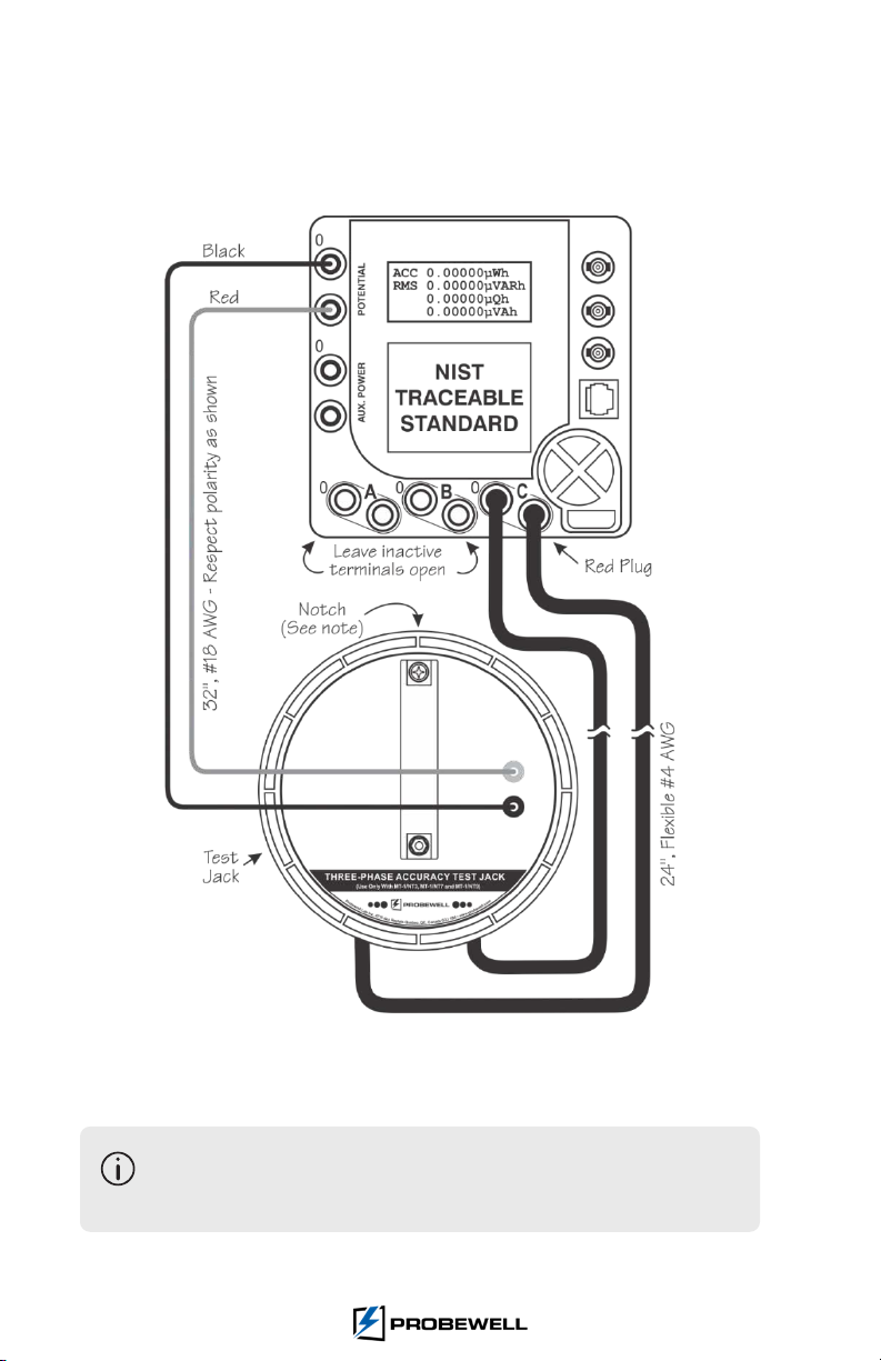
2. Install the test jack on front of the unit in test. Connect the current and voltage
wires between the test jack and the standard while respecng the polarity (see Fig.
3). Refer to the Standard’s manufacturer for details on how to connect the Aux.
Power ports.
Fig. 3 – Test jack (ATK-3 or ATK-4) to Standard Connecon
To remove the test jack, power o the unit and insert a large at screwdriver
in the notch located on the boom side of the rim to pry it out of the unit
in test.
CHAPTER 3: NT SERIES TESTER
9
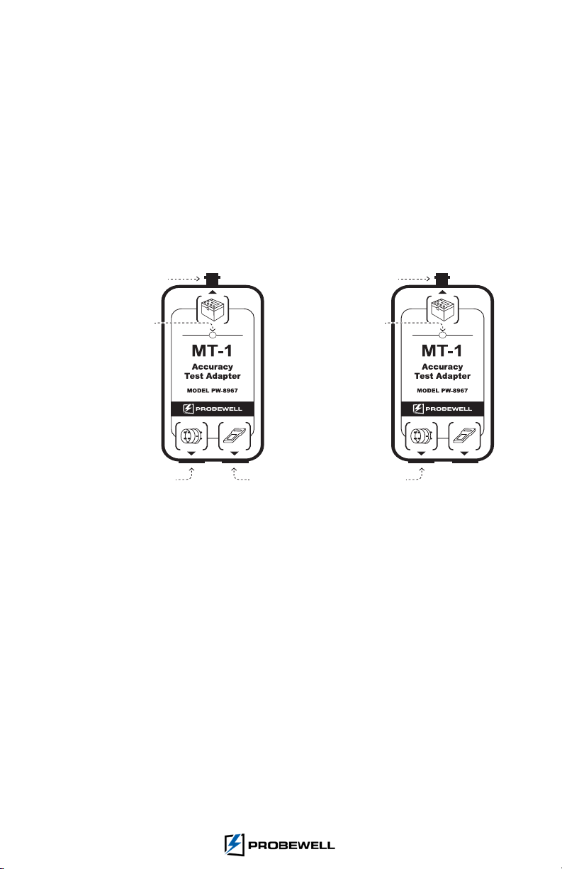
3. Connect the coaxial cable from the Input (pulses) BNC connector on the Accuracy
Test Interface to the output pulses BNC connector of the Standard. Then, connect
the unit in test’s I/O port to the Accuracy Test Interface (port 1, le) with the
provided RJ12 extension cable. For NT series, connect the handheld remote to the
other port of the Accuracy Test Interface (port 2, right) using a RJ12 extension cable.
For WT series, port 2 of the Accuracy Test Interface is unused.
The Accuracy Test Interface is powered by the test socket itself. A red LED
indicates the presence of power.
NT Series WT Series
Input (pulses)
Power Led
To the
Test
Socket
To the
Handheld
Remote
Input (pulses)
Power Led
To the
Test
Socket
Fig. 4 - Accuracy Test Interface

ACCURACY TEST KIT USER GUIDE FOR ATK-3 & ATK-4
10

CHAPTER 3: NT SERIES TESTER
11
Chapter 3
NT Series Tester
AccuracyTesngProcedure(NTSeries)
1. Turn on the AC power source. Hold the Reset Key of the handheld remote and turn
on the unit in test. Aer a few seconds, the Conguraon Menu appears on the
handheld. The Reset Key must be held unl the following screen appears:
2. Use the Mode Key (press mulple mes) to navigate to the Accuracy Test sub-menu
which will appear on the second line of the display screen. The following display
should appear.
3. Press the ENTER Key to access the Accuracy Test sub-menu. The following display
should appear.
By default, the pulses are set at 10µWh/pulse. Use the arrows to select the pulse
rate (10 or 20µWh) and power factor (PF) which can be either 1 (0o) or 0.5 (60 o) lag.
For MT-1/NT9 you also have the opon to verify the VARh at 30 o and 90 o lag.
The µWh/pulse values of the standard and handheld must match.
ACCURACY TEST KIT USER GUIDE FOR ATK-3 & ATK-4
12
4. Press the Start Key to begin the test. The unit in test runs an inializaon sequence
which includes checking the wiring setup and auto-scaling.
If the cables are not properly connected, an error message appears on the
remote. For maximum safety, turn o both the AC power source and unit
in test. Check all the connecons (polarity) and go through steps 4 to 7
again.
Don’t forget to congure the standard in Wh (wahour) mode. Make
sure that the coaxial cable between the Standard’s output pulse and the
Accuracy Test Interface is properly connected.
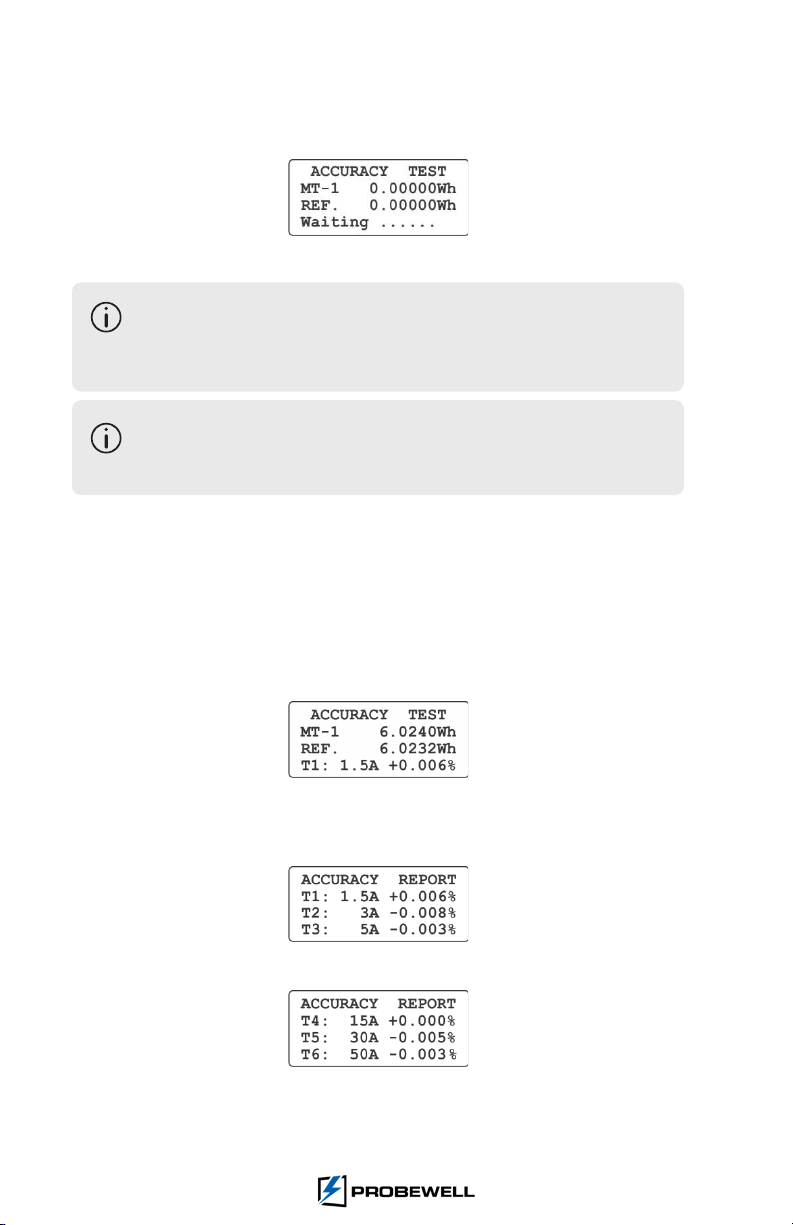
5. Aer inializaon, the test begins automacally. The second line displays the energy
(Wh) recorded by the unit in test. The third line displays the energy (Wh) measured
by the standard. The fourth line shows the current test point being tested in amps
and the % error. The % error shall converge (less than 20 seconds) towards the
result.
6. At the end of each test point, the unit in test emits a single beep. The result is dis-
played for a period of 5 seconds aer each test point.
7. When all 6 test points are completed, the unit in test emits a triple beep. This in-
dicates the end of the test. At this step, the handheld displays results for the rst
3 current points.
8. Press the Mode Key to navigate through the results.

CHAPTER 3: NT SERIES TESTER
13
9. Press the Mode Key again and a summary report showing the accuracy of the unit
test appears on the display.
If the average error of the unit is within specicaon, it does not need to be
calibrated in shop. Otherwise, please follow the User Calibraon procedure to apply
a user dened calibraon factor.
The unit’s internal Wahour Standard does not contain potenometers or
any other type of mechanically adjusted device that could shi or become
unstable with me. This means that the accuracy should not change
much over the lifeme of the product. However, if a unit does need to be
recalibrated, follow the User Calibraon procedure on the next page.
10. To save the Accuracy Report, press the Reset Key once and the Saving Menu
appears. Press the PF Key to save the Accuracy Report in the non-volale memory
of the handheld.
UserCalibraon(NTSeries)
Once the test procedure is complete, the user may choose to apply a specic, single
percentage calibraon oset to the unit. This is useful when the unit calibraon must
match a NIST traceable standard. The maximum value for this oset is ± 0.05%, by steps
of 0.001%. The deviaon is set at 0.000% (nil) by default. The User Calibraon correcon
factor is stored in the non-volale memory of the unit socket.
Procedure
1. Write down the average error percentage result given by the accuracy test. Exit the
Accuracy Test Menu by pressing twice on the Reset Key, then press the Mode Key
to reach the User Calibraon menu entry and press the ENTER Key to access. The
following sub-menu appears:
To change the calibraon factor, use the arrows to decrease or increase the deviaon
percentage.

ACCURACY TEST KIT USER GUIDE FOR ATK-3 & ATK-4
14
Calibraon Factor
When the average error given at the end of the accuracy test is posive, the unit measures
more energy than it should and must be slowed down by that amount. Therefore, the
absolute value of the error should be subtracted.
When the average error given at the end of the accuracy test is negave, the unit
measures less energy than it should and must be speed up by that amount. Therefore,
the absolute value of the error should be added.
Example1: If the average error is +0.028%, and the value in the sub-menu is
-0.005%, subtract 0.028% and the value shown on the display be-
comes -0.033% [ -0.005% - 0.028%].
Example2: If the average error is +0.028%, and the value in the
sub-menu is +0.035%, the new value would be +0.007%
[ +0.035% - 0.028 %].
Example3: If the average error is -0.026%, and the value in the
sub-menu is -0.035%, the new value would be -0.009%
[ -0.035% + 0.026%].
Example4: If the average error is -0.029%, and the value in the
sub-menu is +0.008%, the new value would be +0.037%
[ +0.008% + 0.029%].
2. Once the new value is wrien in, press the Reset Key. You are then asked to enter
the calibraon date (the default date is the current one). The following appears:
3. Once the date is set (using the eding keys), press the Reset Key twice and the
Saving Menu appears. Press the PF Key to save the new value in the non-volale
memory of the NT Series socket meter tester. The unit is now calibrated against
your traceable Standard.
At power on, the message Cal yyyy/mm/dd appears on the display.
Without parentheses, the date indicates when the unit was calibrated
by Probewell before shipment. When the message is shown between
parentheses, it means that the unit has been calibrated according to
your specicaons in your own shop.

CHAPTER 4: WT SERIES TESTER
15
Troubleshoong(NTSeries)
The following are some of the common issues that may occur when using the Accuracy Test
Kit and suitable soluon to resolve them. If issue persists, please contact Probewell Technical
Wrong Setup
• This message appears when no pulse is detected from the Wh standard. Check the
wiring setup at g. 2. Be sure that the polarity is respected.
• Make sure that the standard is set up in Wh (wahour) mode.
• Make sure that the coaxial cable linking the Standard’s pulse output to the Accuracy
Test Interface input is properly connected.
• Make sure that the energy/pulse constant (in µWh/pulse) from the Standard matches
the input pulse selected on the handheld.
Line Voltage Out of Range
• Line voltage is o by more than 5% of the nominal voltage. Check the voltage of the
AC power source.
High Burden could aect calibraon
• Make sure that the screws of the voltage and current ports on the Standard are ght
enough. If necessary, use a ½’’ box wrench to ghten.
• An abnormally high burden may prevent the current from reaching 40 A. The
calibraon cannot be completed under such condions.
• With a medium, but sll acceptable burden load, the maximum test current will be
limited. The max value will lie between 40 A and 50 A. The calibraon can sll be
done, but only up to the highest load that can be reached (e.g. 45 A).
• Make sure that the front jaws of the unit in test are clear of corrosion and debris. If
the problem persists, try switching to another output port of the Standard for current.
Please keep these points in mind if your Calibraon report diers
from the one provided by Probewell
• There may be Small deviaons in the AC power source. Distoron on the AC
voltage waveform will result in a reducon of accuracy proporonal to the order and
magnitude of the harmonics. To minimize waveform errors, the AC voltage waveform
must be sinusoidal and as pure as possible.
• Avoid using line regulators that contain a self-resonant transformer. Those generate
strong harmonics of several kHz.
• Avoid using small (100 VA and less) transformers as the AC power source. Such small
transformers produce strong harmonics of several kHz and introduce measuring
errors on both the MT-1 unit and the standard that can reach ± 0.05%. Harmonics
are produced by the magnezing current drawn by the core (not sinusoidal) and the
relave high winding resistance.

ACCURACY TEST KIT USER GUIDE FOR ATK-3 & ATK-4
16

CHAPTER 4: WT SERIES TESTER
17
Chapter 4
Accuracy Testing Procedure
(WT Series )
Pairing the device
1. Turn on the AC power source. Turn on the unit in test. Once started, the unit will
emit a three-tone sound sequence.
2. Launch the Probewell Connect 2.0 applicaon from your computer.
The following screen should appear:
Fig. 5 – Probewell Connect 2.0 inial display
3. Pair the computer to the unit’s wireless network.
For instrucons on how to
connect to the unit’s network, please refer to the
Connecng to the MT-1/WT
secon in the tester User’s Guide or the connecon
guidelines provided with the unit.
ACCURACY TEST KIT USER GUIDE FOR ATK-3 & ATK-4
18
AccuracyTestSengs
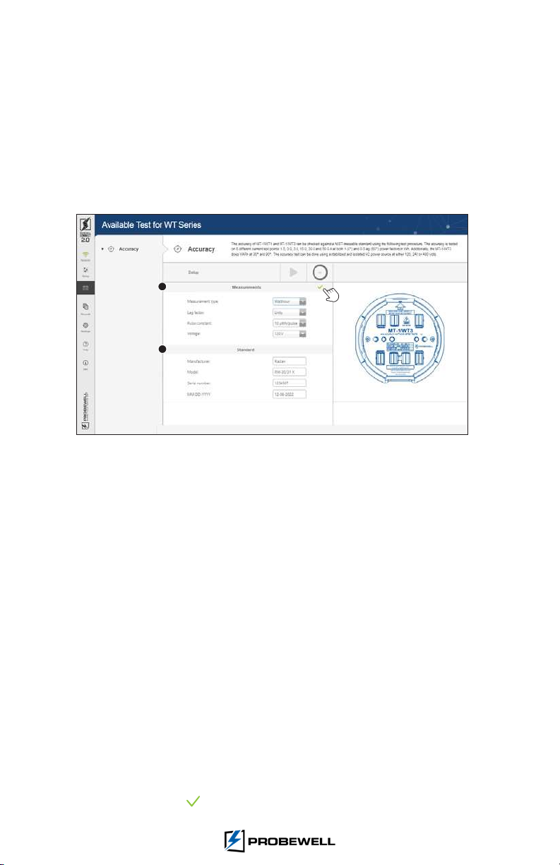
1. Upon connecon, Probewell Connect 2.0 automacally displays the Setup tab.
2. The Measurements secon (1) of the Accuracy Test screen displays the congurable
test parameters and the Standard secon (2) shows the reference Wh standard
idencaon parameters (
The congurable standard idencaon parameters are
self-explanatory and
are only used for traceability, but
the date eld is mandatory and
will be used as the standard’s calibraon date
).
Fig. 6 – Probewell Connect 2.0 Accuracy Test (Test Parameters)
ThecongurableAccuracyTestparametersare:
Measurement type
Wahour or VARHour. Must match the pulse output parameter of the reference
standard.
Lag factor
Unity (100% PF) or Half-Power (50% PF). Translates to a 0o or -60 o phase angle in
Wh and to a 90 o or 30 o phase angle in VARh.
Pulse constant
10 µWh/pulse or 20µWh/pulse. Must match the pulse output parameter of the
reference standard.
Voltage
Between 120 and 480 Volts. Must match the AC voltage source and be within 5%
of the specied value.
Frequency
Not congurable. Set at 60 Hz.
3. Congure the measurement parameters and ll in the Standard secon, then click
the green checkmark to conrm the sengs.
1
2
CHAPTER 4: WT SERIES TESTER
19
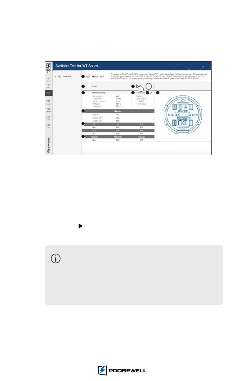
Main Accuracy Test Screen
1. Once the informaon on the Setup tab have been lled in and conrmed, the user is taken
to the main test screen.
Fig. 7 – Probewell Connect 2.0 Accuracy Test screen
1. Test ID and descripon
2. Status eld
3. Control (Start and Stop test)
4. Measurement parameters
5. Reference Standard ID
6. Edit Measurement and Standard eld
7. Tester model
8. Results
9. Six test points
10. Minimum, Maximum and Average
2. Press the Play buon to begin the test. The unit in test runs an inializaon
sequence which includes checking the wiring setup and auto-scaling.
• If the cables are not properly connected, the applicaon displays
an error message. For maximum safety, turn o both the AC power
source and unit in test. Check all the connecons (polarity) and
validate the value of the Measurement parameter secon.
• Don’t forget to congure the standard in Wh (wahour) mode. Make
sure that the coaxial cable between the Standard’s output pulse and
the Accuracy Test Interface is properly connected.
3. Aer proper inializaon, the test begins automacally.
1
2
4
8
9
10
5 6 7
3
ACCURACY TEST KIT USER GUIDE FOR ATK-3 & ATK-4
20
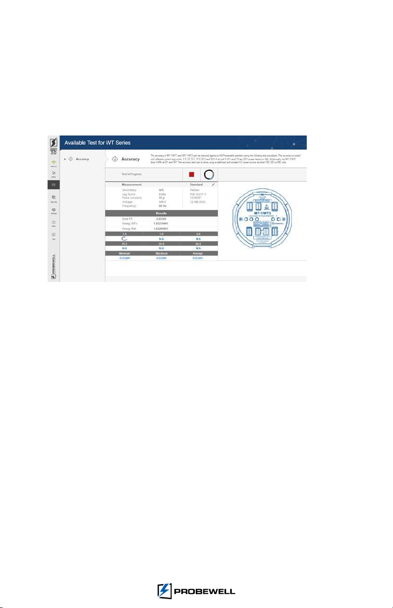
While performing the Accuracy Test
4. The status eld reads «Test in Progress»
5. The current test point being tested is idened by a spin wheel.
6. At the end of each test point, the unit in test emits a single beep. The % error of the
current test point is registered, and the test result table is duly updated.
Fig. 8 – Probewell Connect Accuracy Test (Test in progress)
7. The boom poron of the Accuracy Test display shows the test results.
This manual suits for next models
1
Table of contents
Other Probewell Test Equipment manuals

Probewell
Probewell ST-3 User manual

Probewell
Probewell ST-3/XT3 User manual

Probewell
Probewell ST-3 User manual

Probewell
Probewell MT-1/WT1 User manual

Probewell
Probewell ST-3/XT3 Instruction manual

Probewell
Probewell ST-3 Instruction Manual

Probewell
Probewell MT-1/WT3 User manual

Probewell
Probewell MT-1/WT3 User manual

Probewell
Probewell ST-3 User manual


